Chinderah Service Centre Pacific Hwy
|
|
|
- Lesley Welch
- 5 years ago
- Views:
Transcription

1 Chinderah Service Centre Pacific Hwy

2 The Chinderah Service Centre opened in late The centre services northbound traffic on the Pacific Highway near the Queensland boarder. The development consists of a Caltex petrol station, Coffee Club, Macdonald s, KFC and Oliver s and sees 30,000 to 60,000 visitors per month. Upgrades to the Pacific Highway to the south is expected to increase northbound traffic in the coming years. Figure 1 Northbound Chinderah Service Centre The development is located approximately 5km South of the Queensland Border, and is not serviced by existing sewerage service networks. Therefore, it required a Sewage Treatment Plant (STP). The development posed several key challenges for effective sewage management due to seasonal flooding, small size of the site, high ground water, variable peak loads and varied contaminant concentrations. Hydraulic Flows Flows will vary significantly with seasonal influxes of visitors, therefore the STP must be capable of reliably managing and treating varying flow volumes. Influent Strength The Service Centre includes several commercial fast food tenants. While some pre-treatment is undertaken, the STP must be capable of handling influent with contaminant concentrations beyond domestic levels. Reliability The Chinderah Service Centre is highly visible to highway traffic and is located within a flood prone region. The STP must be highly reliable and include contingency and safe guards to ensure continuity of service at all times. 1
 Figure")

3 Figure 2 Aerial View Chinderah Service Centre (Pre-Works) Figure 3 Aerial View Chinderah Service Centre (During Civil Construction) 2
 Figure 5 Aerial View")

4 Figure 4 Aerial View Chinderah Service Centre (Completion) Figure 5 Aerial View Chinderah Service Centre During 2017 Floods (Note Mounds are not impacted by flood) 3

5 Scott PDI Owners and developers of the Chinderah Service Centre, Scott PDI is an Australian family-owned infrastructure, construction and materials company. Focused on long term investment returns, Scott PDI are active investors in the Property assets. Since the groups formation, they have completed an extensive list of retail property developments, finishing over 50 such projects throughout Queensland, New South Wales, Victoria, Tasmania and South Australia. Scott PDI have worked with most of Australia's largest retailers and understand the process of delivering bulky goods, supermarket anchored shopping centres, discount department stores, hotels with large format liquor barn offers and service stations. Figure 6 Chinderah Service Centre Entrance Assessment of STP Options Scott PDI in conjunction with Hutchinson Builders undertook extensive research and assessed all sewage treatment solutions and providers available in Australia to find the best outcome for their development. The assessment involved investigation into multiple treatment technologies, performance history, company background, operational practices and multiple site visits. Additional factors that were assessed included scalability, capital and operational costs, configuration and aesthetics (visual, odour and noise). When considering site constraints, longevity, life cycle management and the potential future increase in demand, it was concluded the only solution that meet the project requirements was the STP and Land Application system proposed by True Water Australia. Operational security was a key consideration and it was agreed the supply of a scalable 40kL Kubota sewage treatment plant discharging to a mound system gave the best amenity and aesthetic outcome. True Water Australia was then engaged to undertake consultancy, manage regulatory application and approvals, complete project delivery, commissioning and provide ongoing project management. 4


6 Reference Project Stakeholders 5
7 Chinderah Service Centre System Design and Approval 6

8 Chinderah Service Centre Sewage Treatment Plant The Sewage Treatment Plant selected for the Chinderah Service Centre is a 40kL Kubota K-HC-T STP with capacity for expansion to 100kL. The STP site plan and system configuration are provided in Figures 7 and 8 respectively. Treatment Design and Process Influent Flow Influent flow 40m 3 /day General Influent time 12 hours Peak flow factor 4 Water Quality Item Average Influent EA Discharge Licence ph BOD (mg/l) 200 <20 SS (mg/l) 250 <15 E.Coli (cfu/100ml) - <100 Specifications Treatment Method: Structure and Material: Moving Media Bed process Moving Bed Media Polyethylene skeleton type (28mmØ x28mmh) STP Body Fibre Reinforced Plastic (FRP) Aeration Blower Rotary Vein (3phase 415V, 50Hz) Aeration Strength (Moving Bed Chamber) 1.6m 3 /m 3 /hr Airlines Stainless and UPVC Piping Stainless and UPVC Process Flow Diagram Figures 7 and 8 detail the treatment process employed within the Kubota STP. Figure 7 Kubota K-HC-T Treatment Process Flow 7
9 Figure 8 Treatment Process Kubota K-HC-T STP 8

10 Figure 9 STP Site Plan Chinderah Service Centre 9

11 Figure 10 3D System Layout Chinderah Service Centre 10
12 Figure 11 STP Schematic Chinderah Service Centre 11

13 Land Application Mound Treated water from the STP is stored in an Irrigation Tank. A dual pump set transfers treated water to a 2400m 2 Mound system located near the front of the development. All water is discharged underground ensuring there is no odour. Mounds require 1/8 th the area of irrigation for water discharge and can be expanded as required. The mounds are mown regularly and provide simple, safe and low cost discharge of treated water. Figure 12 Chinderah Service Centre Mound Area Figure 13 Chinderah Service Centre Mound Cross-section 12

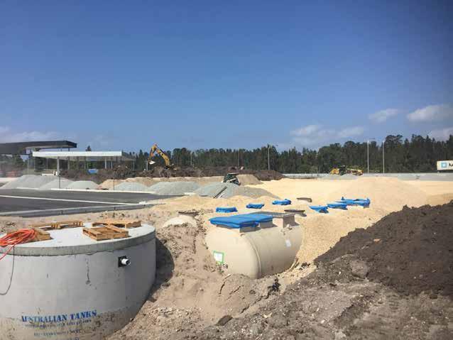
14 Infrastructure Delivery Chinderah Service Centre Sewage Treatment Plant Detailed Design - Duration: 6 weeks Detailed design and system configuration is completed for each STP to ensure the STP is suited to project specific requirements. For the Chinderah project third party consultants had been engaged and had completed an undersized and inappropriate design which consisted of an undersized and unscalable 18kL above ground STP located within 5meters of the drive through entry to McDonalds and KFC. The initial system design had to be changed but had already been submitted to regulators. To keep the project on track True Water worked closely with council, client and builder to achieve approval within 8weeks. Manufacturing and Fabrication - Duration: 12 weeks The STP was manufactured to specifications by Kubota. True Water fabricate and assemble all additional componentry including STP controller, telemetry, airlines, transfer piping, pump sets and odour control units prior to dispatch to site. Manufacture and assembly was complete adhering to strict quality assurance processes and minimises risks associated with onsite assembly. Installation - Duration: 2 weeks Due to in factory manufacture and assembly, installation is completed promptly and efficiently. The STP is installed below ground to eliminate visual and odour impacts, minimise temperature fluctuations and reduce deterioration caused by exposure to weather. Photographs of the Chinderah Service Centre installation are provided below. Testing, Commissioning and Handover - Duration: 1 week Testing, commissioning and handover occurred once the system commenced operation. The process included quality assurance assessment of installation, testing of componentry and redundancies, and NATA laboratory testing of treated water. Installation Photos 13

15 14


16 15


17 16


18 Sewage Treatment Plant Overview Collection Sewage and wastewater is collected from the service centre within a gravity drainage network which discharges to a series of grease arrestors. Pre-Treatment Influent from each individual tenancy passes through its own Halgan Grease Arrestor prior to entering a Sewage Pump Well. The Grease trap is to be strictly maintained in accordance with the site management plan, preventing grease and oil from entering the Treatment Plant. Maintenance and pump out of the grease arrestors is managed by the property manager. Sewage Pump Well A 10kL sewage pump well is located at the rear of the service centre. All waste from the grease arrestors and other drainage systems discharge to the pump well which is sealed to prevent odour. Two grinder pumps are located within the sewage pump well and transfer all sewage from rear of the the service centre to the STP. 17


19 Solid Liquid Separation Tank The Solid Liquid Separation Tank is a reinforced Concrete 20kL chamber which collects all influent entering the STP. Solids are separated during a settling process. The chamber is sealed gas tight, then is vented with a charcoal filter to prevent odour. Anaerobic Filter Chamber The anaerobic filter chamber is aerated via timer at 30minute intervals using a mixing blower. Water moves though this chamber and is transferred via gravity flow to the Aerobic Media Chamber. Aerobic Media Chamber (Moving Bed) Wastewater flows from the Mixing Box to the Aerobic Media Chamber. Access to this chamber is via three inspection openings. The chamber contains cylindrical Polyethylene skeleton type media cubes which provide filtration of wastewater. Circulation Chamber The Circulation Chamber provides a continuous circulation of wastewater back to the solid separation tank. Recirculation automatically adjusts to suit incoming flows. This chamber includes a suction tube used to collect floating objects and return them to the Sludge Tank. 18


20 Carrier Filter Chamber The Carrier Filter Chamber contains caged media in the centre of the chamber. Water must pass through this small media as it flows through to the next chamber for disinfection. The Carrier Filter Chamber is aerated each night between 12am and 2am to degas media. Treated Water Chamber Water passes through a chlorine contact chamber eliminating any residual pathogens as it enters the Treated Water Chamber. Treated water flows to the Irrigation Tank for transfer to land application. Treated Water Chamber The Treated Water Chamber is the final chamber in the Kubota Treatment plant. It is stores treated water prior to discharge via the mound system. 19


21 STP Components Chinderah Service Centre Sewage Treatment Plant Control Panel The control panel used is manufactured by Mitsubishi in Japan. The control panel is user friendly, incorporating a simple touchpad connected to the PLC, and monitors all operation and faults for the STP. Telemetry The STP includes real time monitoring through the integration of a 3G telemetry module. The telemetry module reports operation, alarms and faults as they occur. Data collected by the module may also include operation of blowers, pump, power, backwash flows and daily flow information. 20


22 Blowers The STP uses two Tohin, rotary vein oil lubricated blowers, in a duty standby configuration, for aeration and air lift. The blowers are specified due to there low operating cost, simplicity and longevity. The blowers are housed within a powder coated aluminium housing to stop noise and allow easy access

23 Irrigation Pumps The STP utilises Grundfos centrifugal pumps in a duty/standby configuration. The dual pump controller alternates between each pump for even wear. The irrigation pumps transfer treated water from the Irrigation Tank to the storage lagoons. 22

24 Odour Control The Kubota STP is a gas tight system preventing any potential for escape of odour. The reinforced concrete solid/liquid separation tank has an odour filtration and vent device fitted to further ensure no odour is released during the treatment process. 23

25 About Kubota Established in 1890 Kubota operate throughout North America, Europe, Asia, Oceania and Australia Consolidated sales of $14.4Billion USD in 2015 Currently employees more than 35,000 people Business activity sectors include: o Engineering o Agricultural Machinery o Engines o Wastewater o Water o Environmental o Pipes o Pumps o Valves 24


26 Flagship Projects Chinderah Service Centre Sewage Treatment Plant Kubota Johkasou sewage treatment plants service the following projects: Palm Jumeirah Island Dubai 18,000kL per day Kubota Sewage Treatment Plant Narita Airport Tokyo 1,500kL per day Kubota Sewage Treatment Plant 25


27 Case Studies Similar STP s Central Wastewater Treatment Facility Chinderah Service Centre Sewage Treatment Plant Name of site Location Wastewater type Treatment method Flow rate Water quality Central Wastewater Treatment Facility Japan General Wastewater Membrane Bioreactor (MBR) 267m 3 /day Influent (mg/l) BOD 500 Effluent BOD 1 SS 180 (mg/l) SS 1 T-N 21 T-N 0.3 Image 1: Installation of Advanced Sewage Treatment Plant Image 2: Installation of Advanced Sewage Treatment Plant 26


28 Image 3: Tank Configuration for Sewage Treatment Plant Image 4: Finished Project 27

 SS 1 T-N 21 T-N 0.")
29 Central Wastewater Treatment Plant for rural area Name of site Location Wastewater type Treatment method Flow rate Water quality Central Wastewater Treatment Plant for rural area Japan General Wastewater Membrane Bioreactor (MBR) 160m 3 /day Influent (mg/l) BOD 500 Effluent BOD 1 SS 180 (mg/l) SS 1 T-N 21 T-N 0.3 Image 1: Installation of Advanced Sewage Treatment Plant Image 2: Finished Project 28

 SS 1 T-N 21 T-N 0.")
30 Honda Production Facility Japan Name of site Location Wastewater type Treatment method Flow rate Water quality Honda Production Facility - Japan Japan General Wastewater Membrane Bioreactor (MBR) 220m 3 /day Influent (mg/l) BOD 500 Effluent BOD 1 SS 180 (mg/l) SS 1 T-N 21 T-N 0.3 Image 1: Completed Installation of Treatment Tanks Image 2: Finished Project 29


31 Community Sewage Treatment Plant Name of site Location Waste water type Treatment method Flow rate Water quality Sewage Treatment Plant Japan Community wastewater Moving Bed 62m3/day Influent (mg/l) BOD 200 Effluent BOD 20 SS 160 (mg/l) SS 20 T-N - T-N - Image 1: Installation of Wastewater Tanks Image 2: Installation of Wastewater Tanks Continued 30


32 Community Sewage Treatment Plant Name of site Location Waste water type Treatment method Flow rate Water quality Sewage Treatment Plant Japan Community wastewater Moving Bed 56m3/day Influent (mg/l) BOD 200 Effluent BOD 20 SS 160 (mg/l) SS 20 T-N - T-N - Image 1: Installation of Wastewater Tanks Image 2: Configuration of Wastewater Tanks 31


33 Image 3: Completed Installation of Wastewater Tanks Image 4: Control Boxes for Wastewater Tanks 32


34 Cho Ray Hospital Name of site Cho Ray Hospital Location Vietnam Wastewater type Domestic wastewater Treatment method Moving Bed Flow rate 1,150m 3 /day Water quality Influent BOD 200 Effluent BOD 20 (mg/l) SS 200 (mg/l) SS 50 T-N 40 T-N 30 Image 1: Installation of Advanced Sewage Treatment Plant Image 2: Completion of Installation 33
 Flow rate 530m 3 /day Water")

35 Petro Rabigh Name of site Petro Rabigh Location Saudi Arabia Wastewater type Sanitary treatment plant for refinery plant Treatment method Membrane Bioreactor (MBR) Flow rate 530m 3 /day Water quality Influent BOD 300 Effluent BOD 10 (mg/l) SS 350 (mg/l) SS 10 NH4-N 50 NH4-N 5 T - N 60 NO3-N 10 Image 1: Installation of Advanced Sewage Treatment Plant Image 2: Completed Installation of Sewage Tanks 34

36