LAKE LABELLE DEWATERING MODEL. AUTHOR Gail Murray Doyle, P.G. September Murray Consultants, Inc 769 Skyview Dr Hayesville, NC
|
|
|
- Aubrey Carson
- 5 years ago
- Views:
Transcription

1 LAKE LABELLE DEWATERING MODEL AUTHOR Gail Murray Doyle, P.G. September 2013 Murray Consultants, Inc 769 Skyview Dr Hayesville, NC
2 LAKE LABELLE DEWATERING MODEL INTRODUCTION Purpose The purpose of this drawdown analysis is to determine the potential adverse impacts to adjacent wetlands and domestic wells. The groundwater flow was simulated using Visual MODFLOW. Location of the Study Area The project is located in Hendry County within Section 7, Township 43 South, Range 30 East, Port LaBelle, Florida. Figure 1 shows the location map of the project. Hydrogeology There are three water-bearing aquifer systems in Hendry County: the Surficial, Intermediate, and Floridan Aquifer Systems. In the area of the project, the Surficial Aquifer System (SAS) is generally an unconfined water table aquifer (WTA), about 25 to 60 feet thick and consists mainly of sand, shell, and limestone. Within the SAS at the project area, there is a clay layer at about 25 to 30 feet below land surface. The Intermediate System (IAS) includes the confining unit of the Floridan aquifer and is mainly composed of clays and thin, water-bearing zones of sand, shell, and limestone sometimes called the Hawthorn aquifer. The Floridan Aquifer System (FAS) consists mainly of limestone and dolomite and is about 1,900 feet thick. The FAS consists of the Upper Floridan aquifer (UFA) and the Lower Floridan aquifer (LFA). For this project, withdrawals are from the SAS. MODEL DESCRIPTION Introduction The United States Geological Survey modular three-dimensional finite-difference ground water flow code, commonly known as MODFLOW (McDonald and Harbaugh, 1988) was used to simulate the groundwater flow. The model code is structured with a main program that can retrieve independent subroutines called modules. Each module deals with a specific feature of the hydraulic system to be modeled, such as recharge, evapotranspiration, rivers, drains, wells, and other sources and sinks of water external to the model (boundary conditions). Several iteration solution options are available; for this model the WHS Solver (a Bi-Conjugate Gradient Stabilized acceleration routine) was used. The solution was achieved by using 10 time steps for the transient model runs. Lake LaBelle Dewatering Model September 2013 Page 1
3 The model is designed such that a no-flow boundary is implicit along the outer edges and bottom layer of a model grid. To insure that the simulated flow would not be affected by this boundary, the model domain was set at 20,000 ft by 20,000 ft. The model grid cell size around the mine is basically 125 feet by 125 feet, with the remaining cells expanded. One layer represents the SAS. The bottom of the layer is set at the clay layer, 25 feet below land surface. Boundary Conditions/Model Cell Types This model is designed as strictly a drawdown model. All starting heads are set at zero (0). All cells within the model are active cells for all runs. The Drain package was used to simulate the dewatering and the Constant Head package was used to simulate the recharge water. Hydraulic Characteristics The surficial aquifer hydraulic conductivity used is from a project (Alban-Gould) located about 10 miles northwest of the site. Presented below are the aquifer parameter values used in the model: Hydraulic Conductivity 67 feet/day Specific Yield 0.2 Bottom Elevation -25 feet Evapotranspiration/Recharge To reflect a worst case modeling scenario, no rainfall or evapotranspiration were included. MODEL DISCUSSION AND RESULTS There are five (5) proposed dewatering cells. During the dewatering of cell #1, the discharge will go to the recharge ditch located on the east and south side of the mining area and overflow into the adjacent lake north of the project. The recharge ditch along the south side will run from the eastern corner of the project to the west side of cell #3 and the east ditch will run up to just below the existing lake. When dewatering cells #2 and #3, the water will flow into the previously mined area and the recharge ditch. Discharge water from mining cells #4 and #5 will go into the previously mined areas. The model was run for 90 days assuming the water within the pit will be held at 25 feet below land surface and that the recharge ditch and other recharge areas will be held at no less than on (1) foot below land surface. The results of the projected drawdown for each cell are shown in Figures 2 through 6. The projected drawdown for each cell dewatering have minimal potential to adverse impact to wetlands or adjacent domestic wells. Lake LaBelle Dewatering Model September 2013 Page 2
4 Model input and output are available upon request. Analysis performed by: Gail Murray Doyle, P.G. #459 September 6, 2013 Lake LaBelle Dewatering Model September 2013 Page 3
5 BIBLIOGRAPHY McDonald, M.G. and A.W. Harbaugh, A Modular Three-Dimensional Finite- Difference Ground-Water Flow Model. Techniques of Water-Resources Investigations of the United States Geological Survey, Book 6, Chapter A1. Lake LaBelle Dewatering Model September 2013 Page 4
6 FIGURES
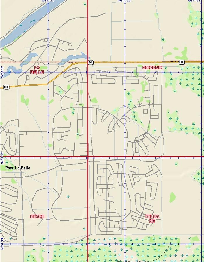
7 FIGURE 1
8 0.5 1 Recharge Ditch Legend Projected Drawdowns for Cell #1, feet Wetlands (SFWMD) Water Resource Consulting 769 Skyview Dr Hayesville, NC SCALE: 1 in = 1,000 ft Projected Drawdowns: Cell 1 Dewatering Lake LaBelle LLC PO Box 250 LaBelle, FL DRAWN BY: DATE: gmd 9/6/13 Lake LaBelle FIGURE NUMBER: 2
9 0.51 Recharge Ditch Legend Projected Drawdowns for Cell #2, feet Wetlands (SFWMD) Water Resource Consulting 769 Skyview Dr Hayesville, NC SCALE: 1 in = 1,000 ft Projected Drawdowns: Cell 2 Dewatering Lake LaBelle LLC PO Box 250 LaBelle, FL DRAWN BY: DATE: gmd 9/6/13 Lake LaBelle FIGURE NUMBER: 3
10 1 Recharge Ditch 0.5 Legend Projected Drawdowns for Cell #3, feet Wetlands (SFWMD) Water Resource Consulting 769 Skyview Dr Hayesville, NC SCALE: 1 in = 1,000 ft Projected Drawdowns: Cell 3 Dewatering Lake LaBelle LLC PO Box 250 LaBelle, FL DRAWN BY: DATE: gmd 9/6/13 Lake LaBelle FIGURE NUMBER: 4
11 1 0.5 Legend Projected Drawdowns for Cell #4, feet Wetlands (SFWMD) Water Resource Consulting 769 Skyview Dr Hayesville, NC SCALE: 1 in = 1,000 ft Projected Drawdowns: Cell 4 Dewatering Lake LaBelle LLC PO Box 250 LaBelle, FL DRAWN BY: DATE: gmd 9/6/13 Lake LaBelle FIGURE NUMBER: 5
12 1 0.5 Legend Projected Drawdowns for Cell #5, feet Wetlands (SFWMD) Water Resource Consulting 769 Skyview Dr Hayesville, NC SCALE: 1 in = 1,000 ft Projected Drawdowns: Cell 5 Dewatering Lake LaBelle LLC PO Box 250 LaBelle, FL DRAWN BY: DATE: gmd 9/6/13 Lake LaBelle FIGURE NUMBER: 6