Memo. Project #:
|
|
|
- Augustine Bridges
- 5 years ago
- Views:
Transcription

1 SRK Consulting (U.S.), Inc. 19 Old Town Square, Suite 238 Fort Collins, Colorado USA Tel: Fax: Memo To: John Hamrick, Cotter Corporation Date: October 26, 2006 cc: From: Rod Grebb, Eric Swanson, Terry Braun, Terry Manziak; SRK Consulting Subject: Dewatering Alternatives, Cotter Corporation, Canon City Milling Facility Project #: Introduction This memorandum provides the basic framework to complete the evaluation of dewatering alternatives for the existing tailings facility at the Canon City Milling Facility and to assess the performance of future tailings deposition alternatives. The purpose of this evaluation is to provide the basis for the development of work plans to study actions that would result in limiting the hydraulic head on the existing liner system with the goal of protecting this liner from damage or failure. The two primary methods of ensuring that this liner is protected are: 1) to dewater the existing tailings facility, and 2) ensure that the placement of additional tailings is in a manner that reduces the total head on the liner as much as possible. To achieve this goal, the overall approach is as follows: Identify Preliminary Alternatives Existing Data Review Review existing technical documentation related to tailings dewatering at the Facility; Identify data gaps, if any, required to assess the performance of an alternative tailings dewatering methodology; Supplementary Investigations to Complete Data Gaps Technical Alternatives Evaluation Existing tailings dewatering alternatives, Future tailings disposal alternatives Implementation of Alternative Actions 2 Identify Preliminary Alternatives Cotter will identify preliminary alternatives in conjunction with input from CDPHE and other entities. These alternatives will be grouped into actions that facilitate the draining of existing tailings and actions that can be taken to ensure that the placement of future tailings are protective of the liner system. SRK has prepared a list of some of the currently identified alternatives, however this list is not considered to be complete at this time. Some of these identified alternatives are described as follows: 2.1 Dewatering of Existing Tailings Based on SRK s experience with tailings dewatering, the following options for dewatering the existing tailings have been identified. Techniques that could be examined to enhance tailings dewatering include:,
2 SRK Consulting Page 2 of No Action This option would involve allowing the tailings to consolidate and dewater at the current rate Liner Drainage System Investigation An initial investigation of the efficiency and status of the tailings underdrain system was performed and presented in previous reclamation plans. The results of this investigation concluded that the tailings drain system is operational; however the results do not indicate the degree of efficiency of this system with respect to the planned design. This investigation also did not address other performance, maintenance or operational issues associated with the liner drain system. Actions associated with this option would include the performance of an additional test of the drain system to gauge how the drainage efficiency is changing over time, and to provide a benchmark to gauge the success of maintenance, remediation and restoration work for the drainage system if needed. Actions that can be taken to increase the efficiency of the drain system include chemical treatment to remove bio-fouling or scale build-up (if present), flushing and removal of sediment build-up within the drain system and filter pack, tele-remote inspection of the drain system to look for areas of failure, and a spatial evaluation of the effectiveness of the drain system in reducing the head on the impoundment liner. If the drainage system appears to be functioning at less than optimal efficiency, Cotter may investigate the feasibility of certain engineering enhancements to the drainage system. These engineering enhancements would include methods of increasing flow through the drainage system above the current levels or even the designed levels. Such engineering enhancements could include actions such as installing a vacuum extraction system within the drains to effectively increase the hydraulic gradient into the system. Other enhancements may include the installation of additional collection points or sumps to increase gradients. Additionally, the effects of additional material loading on the efficiency of the drain system could be investigated. More options to enhance the drainage performance of the system may become evident after the system has been fully inspected and tested. Implementation of this alternative would only take place if the drainage system has been identified as operating at less than peak efficiency. Stating this option does not necessarily imply that the current drainage system is somehow not functioning as designed Installation of Vertical Wick Drain Devices The installation of vertical capillary wick devices within the tailings materials would facilitate dewatering by providing an upward conduit for the dissipation of excess pore pressures within the fine grained materials. The vertical wick devices would consist of linear materials installed in vertical boreholes that penetrate down to the liner, but do not penetrate it. The vertical wick devices function to dissipate hydraulic head that is artesian in nature (e.g. total head pressures that exceed the ground surface elevation). These wick drains also allow the additional dissipation of hydraulic head if the tailings surface is loaded with additional materials such as fill or more tailings. Installation of vertical wick drains requires access to the tailings surface which would require the drainage of the existing pond and the addition of an access media, such as a soil cover, to facilitate drill rig access. Knowledge of material spatial distributions would be required to ensure that the wicks are installed in the most efficient locations within the tails. These vertical wick drains can be enhanced with vacuum extraction methods or can be supplemented by additional air sparging techniques in nearby wells.
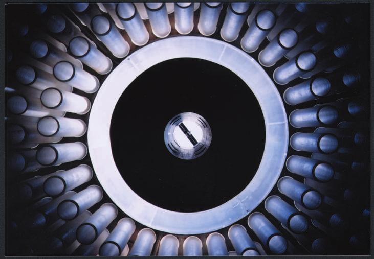
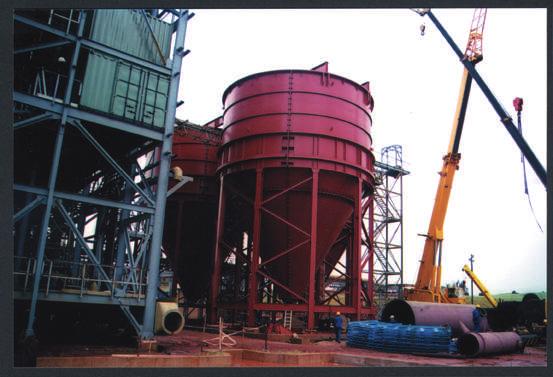
3 SRK Consulting Page 3 of Installation of Dewatering Wells within Impoundment As an alternative to enhance dewatering options, the feasibility of installing traditional dewatering wells within the tailings impoundment (above the liner) could be investigated. Typically, fine grained tailings slimes do not dewater effectively using traditional dewatering wells because of the slow rate at which water penetrates through these materials. Groundwater wells completed in such materials often pump dry and are of limited usefulness. Additionally, traditional wells are often very difficult to install in high pore pressure fine grained materials from an operational perspective. However, the feasibility of installing traditional dewatering wells in the coarse grained tailings areas could be investigated. These wells would act to dewater the sand materials receiving water draining from the fine tailings areas. This method could be effective in areas where the underdrain is not working effectively due to damage, plugging, or other issues. Each of these options could be enhanced by the taking other management actions. One such management action would be the loading of more material on the surface of the tailings impoundment. This loading would facilitate a more rapid dewatering of the facility by increasing the pore pressures at depth thus enhancing the effective hydraulic gradient of the pore fluids from the low permeability materials to the sands or to the underdrain system. This alternative could be used with or with out supplemental wick drains or dewatering wells as described above. Advantages of this dewatering method include 1) the ability to recontour the tailings to a final configuration that sheds incident stormwater, 2) creation of a risk reduction shield limiting environmental contact, and 3) providing an additional radon attenuation barrier. Once the data requirements are met to evaluate these methods, an initial screening level study would be conducted to evaluate the methods against cost, feasibility, and effectiveness. 2.2 Future Tailings Placement Options The other method of reducing head on the liner is to manage new tailings in an optimized manner. Such management practices may include placing new tailings in a dewatered state or optimizing the existing placement method to ensure that the tailings drain properly. Some identified preliminary alternatives for new tailings placement include: No action Optimization of existing slurry placement techniques to facilitate drainage. This method would examine the effects of different placement regimes designed to create a mix of sands and slimes throughout the facility instead of the current regime where the slimes are concentrated in the center of the pond. This option would assume that the consistency of the tailings remain approximately at 50 percent solids. Thickener paste where tailings are thickened in deep cone paste thickener tanks or similar devices to 75 percent solids. Attachment 1 shows examples of equipment used in this type of application. Tailings placed under such conditions would have significantly reduced internal pore pressures and would likely not differentiate into sand and slime components after deposition. Furthermore, deposition of materials in such a manner removes the need to manage tailings using a free water body such as a tailings pond. Disadvantages of managing tailings in such a manner are the very high up-front capital costs and potential operational inefficiencies. Thickener paste and filtering where the thickened tailings are filter pressed to approximately 80 percent solids. This option would include a combination of filtration and thickening technologies to achieve a dewatered material. Placement and management methods would be similar to the deposition of non-filtered paste.
4 SRK Consulting Page 4 of 6 Filter pressing tailing to achieve 80 percent solids tailings. This option would rely on filtration only as the means of achieving a dewatered state. Various filtration technologies exist, and this option would examine all filtration methods given the rheological properties, the cost model, and the operational aspects of filtration implementation. Capital and operational costs would need to be incorporated into the evaluation to assess the possible tailings placement methods for the existing tailings facility. Bench testing would be required to collect sufficient data to evaluate the tailings to determine the placement method. Each of these alternatives may also be evaluated with other options such as the admixture of compounds the increase material strengths (pozzolanic substances), rheological properties (hydrophobic substances), or act as geochemical stabilizers. 3 Existing Data Review Cotter Corporation has an extensive library of facility designs, operational data and other information which will be reviewed and incorporated into the development of dewatering methods. This review will include engineering studies, regulatory review, licensing requirements, and operational practices. The goal of this data review will be to identify if any data gaps exist and what additional data needs to be collected to fill these gaps. Once data gaps are identified, Cotter will develop a work plan to collect this data, execute the work plan, and proceed with a technical evaluation of all the identified alternatives. To perform the technical evaluation of each of the identified alternatives, a significant body of data regarding the performance, costs, characteristics, feasibility, must be gathered. This data is in addition to information describing the existing conditions in the tailings facility such as the location and properties of each of the types of tailings materials. 4 Supplementary Investigations Although significant amounts of data currently exist that describe the tailings facility and geotechnical properties of the tailings materials, it is likely that some additional investigations will be required to fill in data gaps needed to complete the technical evaluation of the identified alternatives. Anticipated data gaps include the lack of knowledge about the spatial distribution of fine tailings materials (slimes) within the facility. Other anticipated data gaps include knowledge of the head under current conditions on the liner within the facility. Finally, a detailed water balance of the tailings facilities is likely to be required in order to evaluation these alternatives. These data gaps may require a subsurface investigation action, which would require the decanting of the tailings pond and the construction of a drill rig access method for the facility surface. It may not be possible to gather certain types of data via field actions and other methods, such as computer modeling, may be required to supply data for the technical evaluation. 5 Technical Evaluation The technical evaluation of alternatives would be conducted after all the data regarding the existing conditions and performance characteristics of the alternative have been collected. The evaluation will be based on the ability of the enhancement to have a significant effect with respect to the head on the liner system. Other performance evaluation criteria include the cost of the proposed alternative, the associated reliability and risks, the impact of the alternative to site operations, and degree to which the alternative may have other effects on the environment and/or human health. The alternatives will also be evaluated with respect to the facility water management plan as well as the facility operations plan, economic model, licensing implications and other regulatory requirements. For each an alternative to be effective, it must be integrated into each of these other management aspects of the site. 6 Schedule and Duration of Investigations Based on SRK s experience conducting similar programs at other uranium tailings facilities, we have developed a schedule that estimates the duration of time required to execute broad actions to investigate, evaluate, select, design, and install a dewatering system. The estimated durations are presented in Table 1.
5 SRK Consulting Page 5 of 6 These estimations are not meant to present a timeline, since other factors such as licensing constraints, water management needs, and mill operation schedules may interrupt or delay actions. Table 1: Duration Estimation Action Item Startup meeting with CDPHE and Cotter to agree on project goals and actions. Data review and development of data needs. Development of additional studies if required. CDPHE review of additional studies and approval. Evaluation of dewatering methods and alternatives. Implementation of additional studies. Evaluation of additional study results. Presentation to CDPHE the evaluation of dewatering methods. CDPHE review of dewatering method evaluations Final Design and CDPHE approval. Contracting and installation of final design. Construction report Monitoring program If additional studies and testing are required; estimated duration to install system. If additional studies and testing are not required; estimated duration to install system Estimated Duration 1 day 1 month 1 month 1.5 months 2 months 4 months 2 months 1 day 1.5 months 4.5 months 4 months 1 month On-going 20.5 months 12 months
6 SRK Consulting Page 6 of 6 Attachment 1


7 Heavy-Duty Equipment that Provides Superior Thickening Capability DORR-OLIVER EIMCO A COMPANY


8 Deep Cone Paste Thickeners... EIMCO Capabilities Paste Disposal Flowsheets Capability Systems Engineering Testing Controls Pumping Construction Paste thickening was initially developed by Alcan International to improve disposal methodology for high-volume, low solids red mud tailings from alumina production. This development program resulted in over 50 Alcan paste thickeners in use around the world in alumina. In 1996 EIMCO entered into an exclusive license agreement for the use of Alcan paste thickening technology in non-alumina applications. EIMCO also provides Deep Cone Paste Thickeners to Alcan within the alumina industry. Since 1996, over 40 EIMCO Deep Cone Paste Thickeners have been designed and sold for thickening red mud, copper tailings, lead/zinc tailings and other mineral tailings for surface disposal, mine backfill, and countercurrent decantation applications. High Unit Loadings EIMCO Deep Cone Paste Thickeners accommodate up to 20 times the solids mass flow and 10 times the hydraulic loading of conventional thickeners. This is accomplished by optimizing solids concentration for feed dilution, chemical addition and floc formation while minimizing floc degradation. These benefits are achieved by using the patented EIMCO E-DUC feed system. This ensures adequate feed pulp dilution, efficient chemical dispersion, rapid flocculation which results in maximum settling rates. Rake Drive & Mechanism Rake drives are key components of conventional and hi-rate thickeners but in paste thickeners, they are absolutely critical. High mud depths that cover the entire rake structure coupled with high viscosities as the underflow reaches paste consistency means that drives must be designed to meet unusually high continuous torque requirements. No company can match EIMCO s experience in providing heavy duty, high continuous torque, long life drives. EIMCO drives use multiple pinions, deep gear faces, precision bearings, oil bath lubrication and strain gauge high accuracy torque measurement to provide the ability to meet this demanding service. These drives can be powered with either hydraulic or electric motors. The rake drive transmits torque to the rake mechanism that is designed to keep the thickened solids flowing toward the discharge and to assist with releasing water from the paste bed. The rake system is designed to minimize drag and to prevent the formation of doughnuts, islands and rat holes that cause process upsets. Left EIMCO Deep Cone Paste Thickener, Right Hi-Rate Thickener 2

9 Heavy-Duty Equipment that Provides Superior Thickening Capability Expanded Disposal Options EIMCO Deep Cone Paste Thickeners are designed to maintain a deep bed of settled solids and maximize gravity compression, achieving discharge solids concentrations that can approach the limits of flowability. Improved water recovery reduces both the volumetric loading on disposal facilities and demand on raw water make up. The ability to control tailings rheology opens up novel disposal options that include underground paste backfill and numerous engineered surface disposal bed alternatives. EIMCO offers complete tailings disposal systems tailored to any specific set of process and regulatory requirements. Increasing Yield Stress Deep Cone Paste Thickener Underflows can Approach a Filter Cake Solids Concentration and Consistency Paste Thickener Operating Range Wt % Solids Feed Increasing Slump Filter Cake Underflow Pump Underflow Pump Cement Added Deep Cone Paste Thickener Delivery Pump Delivery Pump Surface Tailings Disposal Underground Disposal System Capabilities Transportation of the underflow and deposition at the disposal site are major concerns when designing a new paste plant. EIMCO can offer integrated solutions to implement this technology including complete turnkey packages with all peripheral equipment and services required to supply a functioning plant. These services include site, mechanical, civil and electrical engineering, P&ID, instruments and controls, tankage, interconnecting piping, equipment supply, construction, construction management, start up assistance and operator training Countercurrent Decantation Circuit (CCD) Feed To Injection Process Controls EIMCO can design and supply the control system required for the paste thickener system. EIMCO control systems have the ability to optimize a unit operation at the same time as the overall operation of a subsystem or a complete plant. Mix Tank #1 Deep Cone Thickener #3 Deep Cone Thickener Wash Water #2 Deep Cone Thickener #4 Deep Cone Thickener To Tails Transfer Pump 3

 Evaluating Paste Thickeners for Surface Stacking Tailings, Mining Environmental Management, September, 2001.")
10 Walkway Bridge Effluent Weir Effluent Launder Effluent Drop Out Box Rake Drive Motors Polymer Injectors Feed Well E-Duc Nozzle Influent Pipe Rake Shaft Rake Arm Further Information EIMCO is the recognized leader in this important revolution in sedimentation technology. We also offer worldwide sales and service support; global reach, backed by local expertise. EIMCO s full equipment life-cycle support before, during, and after delivery make the EIMCO Deep Cone Paste Thickener an attractive choice. For more information see: Slottee, J. Stephen (2001) Evaluating Paste Thickeners for Surface Stacking Tailings, Mining Environmental Management, September, To request copies of this published article on Paste Systems or to find out how Deep Cone Paste Thickeners can help you, please contact your local EIMCO sales representative. Testing Services EIMCO can conduct bench scale testing to screen potential applications and provide equipment sizing. Pilot Deep Cone Paste Thickeners are available for on site testing to verify laboratory results and confirm sizing. 4


11 Paste Advantages EIMCO Deep Cone Paste Thickeners produce underflow solids with a paste consistency and the highest solids concentration of any thickener on the market. Paste is a non-segregating liquid/solid mixture with a yield stress and slump. The benefits of producing paste are considerable. Maximum liquid recovery for water conservation Disposal by stacking not ponds Total tails backfill disposal Minimum installed thickener area Minimum disposal volume Transportable by pumps Minimum liquid expressed after deposition Highest CCD washing efficiency Minimum pipe plugging problems during shutdowns and upsets Deep Cone Thickening Applications Coarse or fine tailings CCD circuits - superior washing Water conservation Base metals tailings Phosphate slimes Diamond slimes Uranium tailings Power plant fly ash and gypsum An E-DUC Feed System 5
12 Global Sales, Service and Full Equipment Life Cycle Support Orillia Pittsburgh Salt Lake City Rugby Torcy Madrid Hoofddorp Wiesbaden Milan Beijing San Luis Potosi Mexico City Singapore Lima Sao Paulo Johannesburg Santiago Belmont Gosford For a complete listing of office locations, visit or contact our US office at Full Equipment Life Cycle Support Parts Rebuilds Service Filter Media Global reach, local expertise Innovative designs and solutions Proactive service and technical support before, during and after delivery Copyright 2003 GL&V. Form #KD-0202 / EMC Printed in U.S.A. DORR-OLIVER EIMCO doeinfo.slc@glv.com

13 Improving Productivity Through Technology
14 EIMCO Invokes the First, Second, and Third Rules of Engineering Efficiency: Simplify, Simplify, Simplify The revolutionary E-CAT Clarifier-Thickener combines optimized flocculation, high-rate clarification and highdensity thickening in a single compact unit. It streamlines liquid-solid separation process by optimizing use of chemical settling aids and providing a dedicated escape route for displaced free liquid. Even more impressive, the E-CAT System accomplishes all of this with no moving parts. The E-CAT Clarifier-Thickener has Proven Effective in: Leach Feed Gold Tails CCD Circuits Copper Concentrate Cyclone Overflow Copper Tails Potable Water Clarification Uranium Slimes Coal Preparation Plants Coal Fines Wastewater Clarification Steel Mill Scale Carbon Recovery (Gold) Titanium Dioxide Platinum Iron Ore Kimberlite The E-CAT Clarifier-Thickener is the Simple Solution to Reducing the Size and Costs of Liquid-Solid Separation Processes. E-CAT Design Features Operating Advantages No moving parts Smaller surface area than conventional thickeners Self-diluting feed Good overflow clarity Dense underflow Lower capital cost Lower energy consumption Less maintenance Lower capital cost Smaller footprint Optimal flocculant utilization No external dilution pumps required Effluent re-use in plant Lower energy requirement for drying Less area required for disposal pond Reduced handling volume 2


15 Putting it All Together: An E-CAT Walk-through Flocculant Clarified Liquid Zone Inlet Free Settling Zone Hindered Settling Zone Compaction Zone Outside, the E-CAT Clarifier- Thickener features a deep cylindrical tank equipped with a steep-sided bottom cone. Inside, annular rows of clarifying cylinders and a deep feedwell surround a central recycle column and dewatering cones that rise from the compaction zone to the feedwell. No raking mechanism is required to stir or discharge settled solids for most applications. An optional raked E-CAT unit is available for very difficult service applications such as mineral sands and high clay contents. Suspension Overflow Feed/Mixing Well Dewatering Pipe Flocs Clarifying Cylinders Dewatering Cone Sludge Outlet Efficiency in Action: The E-Cat Operating Process Slurry entering the E-CAT unit is piped to the feedwell where it is contacted with flocculent and clarified liquor from the liquid recycle Sizes and Dimensions Diameter Total Height column. Influent turbulence provides ample mixing energy for feed dilution and flocculation. Solid particles agglomerate rapidly and begin settling toward the sludge cone. Here, the weight of accumulated solids concentrated in a deep, narrow cone provides maximum gravity compression and dewatering. Free water displaced from the solids bed escapes via the dewatering cones, enters the recycle column and is returned to the feedwell for influent dilution. The remaining liquor is channeled through the clarifying cylinders. Once in the cylinders, fine solids suspended in the upflow collide and agglomerate, gaining sufficient weight to settle against the upward liquid velocity. This solidscontact polishing action allows E-CAT Clarifier-Thickeners to achieve low overflow effluent turbidities while consistently discharging dense, high-quality underflow. Internal Cylinders Qty. M M Max Min
16 Worldwide Sales, Service and Aftermarket Full Equipment Life Cycle Support Rugby Salt Lake City Mississauga Palatine Pittsburgh Houston Monterrey Lebanon Birmingham Madrid Paris Krefeld Milano Beijing San Luis Potosi Singapore Lima Sao Paulo Johannesburg Santiago Belmont Gosford North America Locations Headquarters Salt Lake City 669 West 200 South Salt Lake City, UT / USA Tel / Fax Sale Offices (US) Birmingham, Alabama Tel / Fax Houston, Texas Tel / Fax Palatine, Illinois Tel / Fax Pittsburgh, Pennsylvania Tel / Fax Vancouver, Washington Tel / Fax Lebanon (Union), New Jersey Tel / Fax Sale Offices (Canada) Mississauga, Ontario Tel / Fax Global Locations Sale Offices (Latin America) San Luis Potosi, Mexico Tel / Fax Monterrey, Mexico Tel / Fax Lima, Peru Tel / Fax Santiago, Chile Tel / Fax Sao Paulo, Brazil Tel / Fax Buenos Aires, Argentina Tel / Fax Sale Offices (Europe, Africa & Middle East) Rugby, England Tel / Fax Madrid, Spain Tel / Fax Milano, Italy Tel / Fax Johannesburg, South Africa Tel / Fax Paris, France Tel / Fax Krefeld, Germany Tel / Fax Sale Offices (Asia Pacific) Beijing, PRC Tel / Fax Singapore Tel / Fax Belmont, Australia Tel / Fax West Gosford, Australia Tel / Fax KnowledgeScape Salt Lake City, Utah Tel / Fax MPS Engineering and Construction Pittsburgh, Pennsylvania Tel / Fax Dealer Imprint Area Full Equipment Life Cycle Support Parts Rebuilds Service Filter Media Global reach, local expertise Innovative designs and solutions Proactive service and technical support before, during and after delivery Copyright 2002 Baker Process, Inc., d.b.a. EIMCO Process Equipment Company. All rights reserved. EIMCO,, and E-CAT are proprietary/registered trademarks/service marks of Baker Hughes Incorporated. Form #KW / EMC Printed in U.S.A.