Concrete Paving in NOVA Conventional and Pervious Concrete & Streets and Local Roads. Rod Meyers, PE, BASF Construction Chemicals
|
|
|
- Anastasia Blanche Bryant
- 5 years ago
- Views:
Transcription
1 Concrete Paving in NOVA Conventional and Pervious Concrete & Streets and Local Roads Rod Meyers, PE, BASF Construction Chemicals


2 How Thick Should The Pervious Concrete Pavement Be?

3 ACI , Report on Pervious Concrete, section Parking Lots The practical range of design thicknesses for pervious concrete pavements is from 5 to 12 in for plain parking lots.
4 VIRGINIA DCR STORMWATER DESIGN SPECIFICATION No. 7 PERMEABLE PAVEMENT VERSION 1.7 March 1, 2011 Table 7.6 Typical Thickness: 4 to 8 inches

5 Light Duty Portland Cement Concrete Pavements

6 Calculating Stresses in Pavement
7 PCA Pavement Stress Calculations Does anyone have a i5 Processor with Turbo Boost Technology?
8 ACPA Design Software Terminal serviceability index Allowable cracked slabs Pavement design life Reliability Traffic inputs
9 Light Duty Pavement Design Long term durability attractive Complex design methods are Overkill Not represented by AASHO Road Test AASHTO design method are overkill Design and QC based on fc
10 Design Tools
11 Types of Concrete Pavement Plain jointed pavement Plain-doweled pavement Reinforced-doweled pavement Continuously reinforced pavement
12 Typical Concrete Roads and Streets Plain jointed pavement Plain-doweled pavement Reinforced-doweled pavement Continuously reinforced pavement

13 Reduce edge stresses Used as side forms Allowed to use rounded joints Curbs and Gutters

14 Functional Requirement Support Traffic Loads

15 Flexural Strength Pavements are subject to bending stresses Flexural stresses and flexural strength govern design

16 Flexural Strength (MOR) ASTM C 78 Third-Point Loading of 6 by 6 by 30 beams High variability with flexural strength testing Results sensitive to specimen preparation, handling and curing procedures
17 Flexural Strength (MOR) from Compressive Strength Data ACI 330 For smooth-textured and round-shaped aggregates MOR = 8 * (f c)1/2 (psi) For rough-textured and angular-shaped aggregates MOR = 10 * (f c)1/2 (psi) f c = specified compressive strength (psi)
18 Flexural Strength from Compressive Strength Data PCA Design and Control of Concrete Mixtures MOR = K * (f c)1/2 (psi) K = factor from 7.5 to 10.0 f c = specified compressive strength (psi)
19 Calculated Flexural Strength, MOR (psi) Compressive Strength, f c (psi) 3,500 psi 4,000 psi 4500 psi MOR = 7.5 * (f c)1/ MOR = 8.0 * (f c)1/ MOR = 8.5 * (f c)1/ MOR = 9.0 * (f c)1/ MOR = 9.5 * (f c)1/ MOR = 10.0 * (f c)1/

20 Flexural Strength based on Compressive Strength MR = 8.7 * fc1/2 fc = 4,000 psi MR = 8.7 * (4,000)1/2 = 550 psi

21 Subgrade Support Concrete distributes load through slab action Load spread over large area
22 Subgrade Support Measured as: Modulus of Subgrade Reaction (k) California Bearing Ratio (CBR) Bearing Value Resistance Value (R)
23 Modulus of Subgrade Reaction (k)

24 Subbase Improves Structural Capacity
25 Improving Subgrade Support with Granular Subbase PCA
26 PCA Thickness Design Axle-Load Data Not Available Simplified design procedure Table 9 Axle-Load Categories Table 10 k values for subgrade type Table 11 Pavement thickness
27 Table 9 Axle-Load Categories
28 Table 10 k values for subgrade type k = 100 pci
29 Improving Subgrade Support with Granular Subbase PCA
30 Table 10 k values for subgrade type k = 150 pci
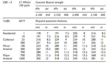
31 Table 11 Pavement Thickness
32 PCA Design of Concrete Pavements for City Streets Method 1 / Table 1 Method 2 Thickness Design Select k-value Chart 1 Pavement thickness
33 PCA Design of Concrete Pavement for City Streets Method 1
34 PCA Design of Concrete Pavement for City Streets Method 2
35
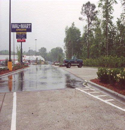
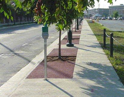
36
37 ACI 330R-08 Thickness Design Table 3.3 Traffic categories Table 3.1 Subgrade support Table 3.4 Pavement thickness recommendation
38 ACI 330. Table 3.1 Subgrade soil types and approximate support values k = 140 pci
39 Traffic categories

40 ACI 330. Table 3.1 Subgrade soil types and approximate support values k = 140 pci

41 ACI 330. Table 3.4 Design thickness recommendations
42 Thickness Design of Pervious Concrete


43 Pervious Concrete Applications Parking lots Streets/roads shoulders Sidewalks Driveways Light traffic areas
44
45 ASTM C1701 Infiltration Rate as a Function of ASTM C1688 Void Content
46 Specified Strength of Pervious Concrete VIRGINIA DCR STORMWATER DESIGN SPECIFICATION No. 7 PERMEABLE PAVEMENT VERSION 1.7 March 1, 2011 Table 7.6 Compressive strength: 2.8 to 28 Mpa (400 psi to 4,000 psi)
47 Calculated Flexural Strength, MOR (psi) Compressive Strength, f c (psi) 400 psi 2,000 psi 4,000 psi MOR = 7.5 * (f c)1/ MOR = 8.0 * (f c)1/ MOR = 8.5 * (f c)1/ MOR = 9.0 * (f c)1/ MOR = 9.5 * (f c)1/ MOR = 10.0 * (f c)1/
48 The American Concrete Institute Committee Report ACI 522R-Pervious Concrete, Chapter states: Guidance for structural design of conventional concrete pavements is provided in ACI 330R for parking lots and in ACI R for streets and roads. These documents cover many different aspects of paving design. The structural design recommendations in these documents, however, are not necessarily applicable for use with pervious pavement. As there are no standardized test methods for strength of pervious concrete, design and specification by strength should be avoided.
49 28-day Flexural Strength, psi Flexural Strength vrs. Void Content Best Fit Line Data Void Content, percent by volume Flexural Strength, Fmr = * (void content, %), psi
50 Specified Void Content of Pervious Concrete VIRGINIA DCR STORMWATER DESIGN SPECIFICATION No. 7 PERMEABLE PAVEMENT VERSION 1.7 March 1, 2011 Table 7.6 Open Void Content: 15% to 25%
51 28-day Flexural Strength, psi Flexural Strength vrs. Void Content Best Fit Line Data Void Content, percent by volume Flexural Strength, Fmr = * (void content, %), psi

52 Testing Fresh Density ASTM C1688 Density and Void Content of Freshly Mixed Pervious Concrete 0.25 ft3 measure (standard air pot) Standard Proctor Hammer


53 ASTM C1688 Obtain sample ASTM C172 Fill in 2 lifts Drop hammer full 12 Drop 20 times/lift

54 ASTM C1688 Void Contents


55 Consistency and Water Content Too little water Proper Amount of Water Too much water (1) Tennis, P.D., Leming, M.L., Akers, D.J., Pervious Concrete Pavements, Portland Cement Association, PCA Serial No. 2828, 2004, page 8


56

57 High water content without stable paste Increases Chances of Aggregate Raving


58 Abrasion Resistance Turning lanes and high traffic volume applications may not be suitable Snow plows may ravel aggregate


59 Flexural Behavior Does not always fail in middle Load Points
60 What Design Strength? Engineering judgment may be the answer

61 Influence of Infiltration Rate of In-situ Soil

62 VIRGINIA DCR STORMWATER DESIGN SPECIFICATION No. 7 PERMEABLE PAVEMENT VERSION 1.7 March 1, 2011 If the proposed permeable pavement area is designed to infiltrate runoff without underdrains, it must have a minimum infiltration rate of 0.5 inches per hour. Initially, projected soil infiltration rates can be estimated from USDANRCS soil data, but they must be confirmed by an on-site infiltration measurement. Native soils must have silt/clay content less than 40% and clay content less than 20%.
63 Group A : > 90% Sand <10% Clay PR > 5.67 in/hr Group B : 10% -20% Clay 50 to 90% Sand PR in/hr Group C : 20% - 40% Clay < 50% Sand PR in/hr Group D : > 40% Clay < 50% Sand PR < 0.14 in/hr Designers should note that if the underlying soils have a low California Bearing Ratio (CBR) (less than 4%), they may need to be compacted to at least 95% of the Standard Proctor Density, which generally rules out their use for infiltration.
 (less than 4%), they may need to be compacted to at least 95% of the Standard Proctor")
64 VIRGINIA DCR STORMWATER DESIGN SPECIFICATION No. 7 PERMEABLE PAVEMENT VERSION 1.7 March 1, 2011 Designers should note that if the underlying soils have a low California Bearing Ratio (CBR) (less than 4%), they may need to be compacted to at least 95% of the Standard Proctor Density, which generally rules out their use for infiltration. CBR Range: 4 to 40 Modulus of Subgrade Reaction: 125 to 400 pci
65
66
67
68 Modulus of subgrade reaction (psi/in) Support Provided by Bedding and Reservoir Layer k=100 psi/in k=200 psi/in Linear (k=100 psi/in) y = x Linear (k=200 psi/in) y = 7.483x Reservoir Thickness (inches) 60

69 Reservoir Layer

70
71 Structural Number System Developed by from American Association of State Highway Officials Road Test Data in 1961 The Structural Number (SN) is analytically given by: SN = a1*d1 + a2*d2 + a3*d3 + a4*d4. where ai = layer coefficient of layer i Di = thickness of layer i
72 Structural Numbers Pavement Component Structural Number Portland Cement Concrete 0.50 Surface Course Asphalt Concrete Hot Mix Base Course Asphalt Concrete Hot Mix Stone Base
73 Specified Pavement Sections

74 Light Duty Parking Lot Pavement 1.5 ACHM Surface 7.0 Pervious PCC 3.5 ACHM Base 8.0 Stone Base 22 Reservoir Section 6.0 PC Concrete 22 Reservoir Structural Numbers 22 * 0.14 = Total SN = 3.08 Section 1.5 ACHM Surface 3.5 ACHM Base 8.0 Stone Base Structural Numbers 1.5 * 0.44 = * 0.34 = * 0.14 = Total SN = 2.97
75 Heavy Duty Parking Lot Pavement 2.0 ACHM Surface 7.0 Pervious PCC 26 Reservoir Section 6.0 PC Concrete 26.0 Reservoir Structural Numbers 26.0 * 0.14 = Total SN = ACHM Base 8.0 Stone Base Section 2.0 ACHM Surface 4.5 ACHM Base 8.0 Stone Base Structural Numbers 2.0 * 0.44 = * 0.34 = * 0.14 = Total SN = 3.53

76 It is just about that sort of thing they would like