Title slide. LNG Technology. Compiled by PD.Supriyadi
|
|
|
- Miles Holt
- 5 years ago
- Views:
Transcription
1 Title slide LNG Technology Compiled by PD.Supriyadi 1
2 What is LNG? Colorless, odorless, non toxic hydrocarbon in very low temperature liquid form (cryogenic) Mainly (90% plus) is Methane, the lightest component of hydrocarbon family LNG is the cleanest hydrocarbon fuel Lightest hydrocarbon All contaminants are removed prior to liquefaction process to meet process or Buyer s requirement Carbon Dioxides Sulphur compounds Mercury Heavy hydrocarbons Aromatics 2


3 LNG Colorless Liqud Boiling Liquid In LNG, ordinary material will become so brittle and break like glass LNG requires special low temperature material for storage 3


4 LNG is Safer Than Other Hydrocarbons LNG has less fire hazard than other hydrcarbon LNG leaks will be easily detected due to visible moisture cloud LNG leaks immediately vaporize LNG pool open fire will not cause any explosion LNG flame speed travel slower than people walking Low temperature hazard Frost byte Cause structural material brittle and fail 4
5 LNG Constituents Tangguh Feed Gas (early Vorwata) H2O : 2.3% N2 : 0.66% CO2 :10.4% H2S :0.0003% Methane :83.22% Ethane :2.2% Propane :0.5% Butane :0.19% Pentane+ : 0.53% g:\depts\152\g\9997 Water CO2, H2S, -HS, Hg Nitrogen Methane Ethane Propane Butane Pentanes + To be removed LNG LPG Gasoline LNG Composition Nitrogen :0.89% Methane :96.64% Ethane :1.97% Propane :0.34% Butane :0.13% Pentane : 0.003% 6 5
 But... much larger size & colder temperature Our typical AC compressor is 1 ~ 2 HP LNG Plant compressors are 80,000 HP Our refrigerator cools to minus 10 Deg.")
6 LNG Process is Simple It uses exactly the same principles of our Refrigerator or Air Conditioners at home It has the same basic components: Compressors (B) Condensers (D) Expansion Valves (C) Evaporators (A) But... much larger size & colder temperature Our typical AC compressor is 1 ~ 2 HP LNG Plant compressors are 80,000 HP Our refrigerator cools to minus 10 Deg. C LNG Plant liquefy the gas to minus 160 Deg. C Our Refrigerator/AC use Freon, LNG Plant uses mixture of Propane, Ethane, Methane & Nitrogen D 6
7 Simplified LNG Process Block Diagram Tangguh LNG Process Block Diagram GAS WELLS PIPELINES CO2 H2S H2O RECEIVING RECEIVING FACILITIES FACILITIES GAS GAS TREATING TREATING LNG LNG LIQUEFACTION LIQUEFACTION LNG Hg CONDENSATE CONDENSATE STABILIZER STABILIZER FRACTIONATION FRACTIONATION CONDENSATE Utilities Supporting Two Trains Operation Utilities Supporting Two Trains Operation Power, Power, Steam, Steam, Water, Water, Air, Air, Nitrogen, Nitrogen, Fuel Fuel Waste Waste Treatment Treatment and and Disposal Disposal Fire Fighting Fire Fighting 7

8 LNG Plant is a Big Air Conditioner COMPRESSORS CONDENSERS 8
9 Of Course, It is not that simple Very low temperature requires special knowledge on structural material, metallurgy, heat transfer and thermodynamics Very large and high speed machineries requires special knowledge on machineries efficiency, precision & fabrication techniques Hydrocarbon environment requires adequate knowledge and commitment on safety Thousands of equipments and machineries requires complicated control system LNG Engineer is a little bit more than just Air Conditioner technician 9


10 Tangguh LNG Flare and Blow down System WF DF MF RECEIVING RECEIVING FACILITIES FACILITIES GAS GAS TREATING TREATING Propane Propane Chiller Chiller Scrub Scrub Column Column FG Dehydration & Hg Dehydration & Hg Removal Removal Condensate Condensate Stabilizer Stabilizer FRACTIONATION FRACTIONATION Gas Treating & Fractionation Propane Propane Compression Compression MR MR Compression Compression MCHE MCHE Compression & Liquefaction LNG Storage & Loading Liquid Drain Liquid Drain Drum Drum 10
11 Propane Precooled Mixed Refrigerant Propane -161 C LNG to Storage Treated Natural Gas -35 C Heavies Removal Column MR Cryogenic Heat Exchanger -35 C NGLs MR Separator Chiller Water Cooler Compressor Joule-Thompson Valve 11

12 ONSHORE RECEIVING FACILITIES 16-D E D-1006 WIRIAGAR 16-A-1001 FEED GAS TO AGRU 16-D E D A-1002 VORWATA 16-D D D D-1005 PRODUCED WATER CONDENSATE 12


13 AGRU Absorption Process Diagram REMOVED ACID GAS REGENERATOR OVERHEAD CONDENSER TREATED GAS ABSORBER WASH TOWER REBOILER LEAN/RICH AMINE EXCHANGER RECIRCULATION PUMP FEED GAS 13
14 AGRU 14
 catalyst Regenerated by hot gas")

15 Dehydration Unit WET SWEET GAS SERVICE SERVICE BOIL OFF GAS REGENERATION H2O freezes and blocked equipments H20 is adsorbed by Molecular Sieve (Silica Alumina) catalyst Regenerated by hot gas heating H2O inlet : saturated H2O oulet : 1 ppm Catalyst life : 4 ~ 6 years BOIL OFF GAS Drying 8 hours Regeneration cycle Heating 2.0 hours Cooling 1.5 hours Standby 0.5 hours DRY SWEET GAS 15
16 16
 Catalyst Life : 6 ~ 10 years per charge DRY SWEET GAS MERCURY")
17 Typical Hg (Mercury) Removal Unit DRY SWEET GAS SERVICE Hg corrodes Aluminum Exchanger Hg is adsorbed by Sulphur Impregnated Carbon No Regeneration Hg inlet : nil, design 100 ppm Hg oulet : 1 ppb ( 1 nanogram/nm3) Catalyst Life : 6 ~ 10 years per charge DRY SWEET GAS MERCURY FREE 17
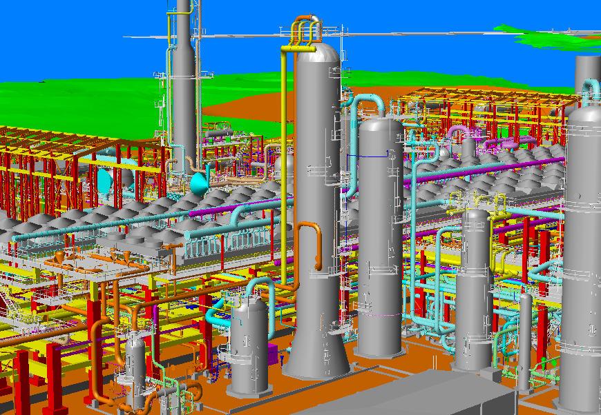
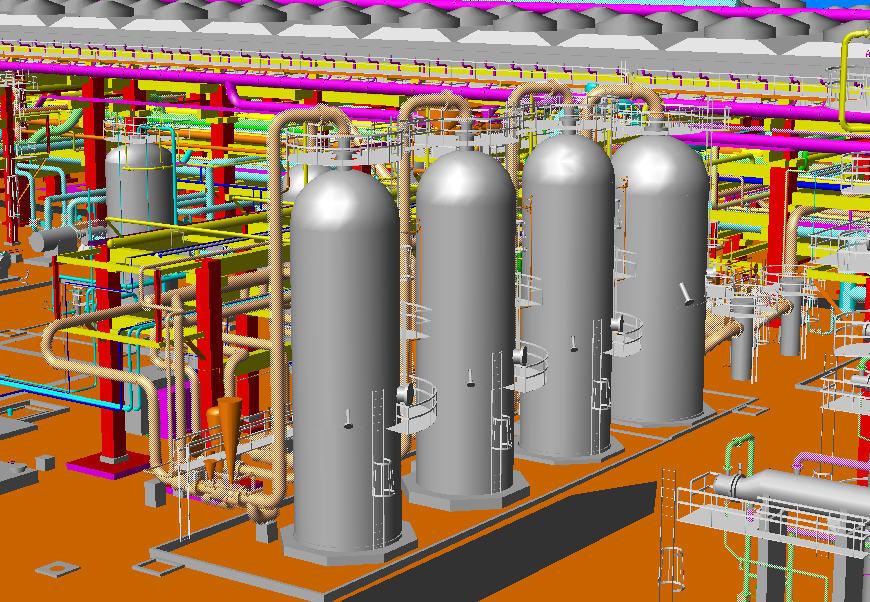
18 Liquefaction & Fractionation 18

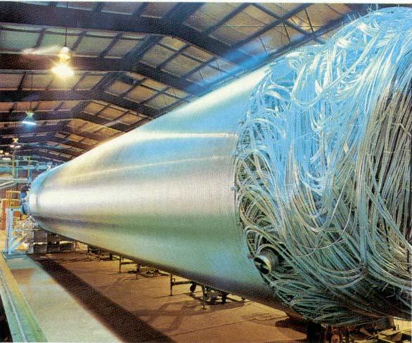
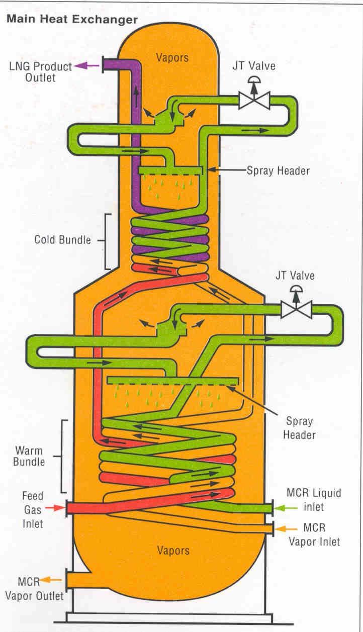
19 LNG - APCI 19
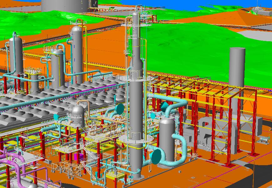
20 Liquefaction & Fractionation 20
21 REFRIGERATION & COMPRESSION REFRIGERANT: PROPANA MR Compressor REFRIGERANT: N2, C1,C2, C3 C3 Compressor 21

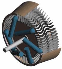
22 Gas Turbines Operation Principles 22


23 GE Frame-7 Gas Turbines 23


24 GE Frame-9 Gas Turbines 24

25 MR Gas Turbine 25

26 Tangguh LNG Process Block Diagram per KJP Proposal Steam Steam LNG From #2 HRSG Fired HRSG Feed Gas To #2 INC WF C3 GTS Heater MR GTS Propane Propane Compression Compression DF MF FG RECEIVING RECEIVING FACILITIES FACILITIES GAS GAS TREATING TREATING Dehydration & Hg Dehydration & Hg Removal Removal Propane Propane Chiller Chiller Scrub Scrub Column Column MCHE MCHE Condensate Condensate Stabilizer Stabilizer Fuel Fuel System System FRACTIONATION FRACTIONATION MR MR Compression Compression LNG CONDENSATE 3 STGs Produced Water Waste Water Waste Water Treatment Treatment St.Condensate Steam G Boilers Boilers Steam To LAT

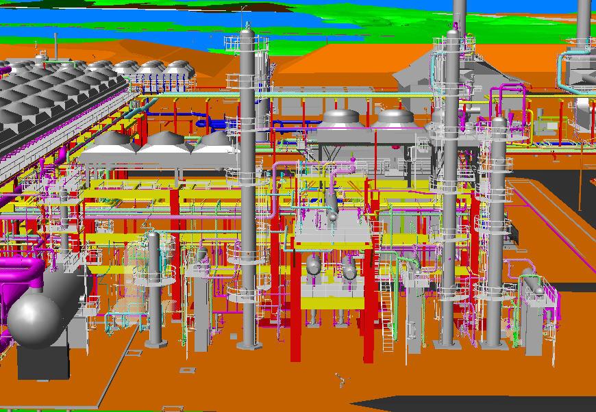
27 UTILITIES 27

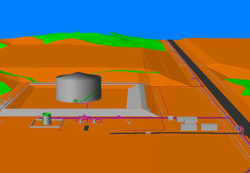
28 LNG Storage 28

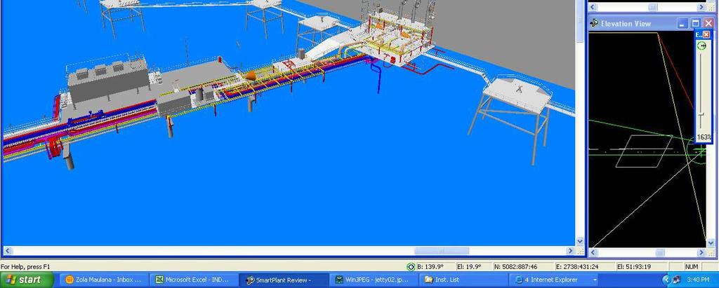
29 LNG Jetty 29
30 Condensate Storage & Loading 30
31 Holding and Loading Base Bid Configuration Holding Mode Loading Mode MCHE MCHE Train-1 Train-1 MF MCHE MCHE Train-1 Train-1 MF MCHE MCHE Train-2 Train-2 LNG MCHE MCHE Train-2 Train-2 LNG Reg Gas Reg Gas Train-1 Train-1 Reg Gas Reg Gas Train-2 Train-2 D/S D/S ORF ORF Reg Gas Reg Gas Train-1 Train-1 Reg Gas Reg Gas Train-2 Train-2 D/S D/S ORF ORF Fuel Fuel System System FG Distribution Fuel Fuel System System FG Distribution 31