IMEC. March PW & HPW Generation
|
|
|
- Vernon Hart
- 5 years ago
- Views:
Transcription


1 IMEC March 2014 PW & HPW Generation

2 CONTENT Introduction In 10 Seconds.. Our Business Approach PHARMA : Purified Water Generation Case Study MICRO ELECTRONIC : High Purified Water Generation Case Study Conclusion

3 VWS : Business Approach Wait for the case Study!!
4 What are we talking about? Water Most commonly used raw material for WFI generation, Bio reactors,cleanings, Sinks, washer units, precleanings, Ingredient made on site Purified Water & WFI generation is part of manufacturing - critical utilities Assurance of supply & regulatory compliance are the key drivers Continuous investment in service needed to ensure ongoing compliance
5 Pharma industry heavily regulated Key process water application is Critical Water Utilities Strong drivers for: Process security Compliance assurance Service
6 What about the Specifications? From Potable Water to: US Pharmacopeia USP- European Pharmacopeia Ph Eur- Japanese Pharmacopeia JP- Some Others
7 USP Monograph Conductivity: TOC: Bacteria: < 1.3 S/cm at 25 C in-line or Table* < 500ppb (Online or off) < 100 cfu/ml** *Non-temp. compensated conductivity measurement **Non-mandatory, generally considered appropriate Action Level
8 Ph Eur Monograph Conductivity Table* TOC: Bacteria: Nitrates < C in-line or < 500ppb < 100 cfu/ml** < 0.2 ppm Heavy Metals < 0.1ppm * Non-temp. compensated conductivity measurement - but more relaxed than USP. ** Appropriate action limit under normal conditions
9 System Design Essential Information Feed water quality - spots samples and annual averages, plus free chlorine and FI/SDI. Treated water specification - for ALL chemical and microbiolagical parameters. Average hourly flow rate, total daily volume, size/duration/frequency of any demand peaks.
10 System Design Significance of Demand Flowrate Generation system usually sized on average hourly flow rate (daily volume over 20 hours). BUT it must be large enough to replenish tank between demand peaks. Distribution system sized on peak demand flowrate % return flow. Pipework diameter sized to give a velocity of 1-3 m/s wherever practical.

11 System Design Typical
12 Design Practices Pretreatment- Pretreatment includes filtration, softening & adsorption processes. Chemical dosing not preferred. Not Allowed! Adoption of distribution system design. parameters at front end is now standard. Focus on control of microbial growth rate. Heat sanitisable treatment units increasing
13 Design Practices Main treatment- RO&CDI, 3 bed DI or twin pass RO processes Philosophy is to overpurify to avoid treatment in the distribution system Main processes and polishing are combined before the tank Heat Sanitisation used wherever possible Trend is to reduce effluent volumes

14 Typical Design PW Generation Hot Water Sanitisable Design
15 Design Practices Storage- Tank is the microbiologically weakest link. Stainless steel, vacuum rated tanks of minimum volume preferred. Spray ball vs dip tube inlet debate. Ozone can be used continuously to control bacteria in the water and air in tank. Tank sizing should be determined by demand profile, not a nominal retention time.
16 Design Practices Distribution System Minimise treatment processes in the loop - bacterial control only. Sanitisation by heating (high energy). Sanitisation with ozone (low energy). Variable speed drives on pumps. Greater quality/flow/pressure monitoring
17 Design Practices Importance of Recirculation- Essential to minimise microbial re-growth. Minimum velocity 1m/s must be achieved. Continuous cooling may be needed if demand is high and/or intermittent. Need to consider peak demand AND zero demand conditions.
18 Design Practices Future Desing Trends- Permanently hot distribution systems Storage tank elimination by managing demand Cleaner pretreatment for potable water (UF,..) Nitrogen blanketing of storage tanks Tightening quality standards (regulatory or clients own) Reclamation of (clean) effluent Reduction of effluent volume ( RWD- Veolia Concept) Reduction of the Carbon foot print
19 Design Practices Conclusions Pharmaceutical system design presents chemical and microbiological challenges Current quality limits are readily achievable Maintaining water quality is the major challenge Though many processes could be used, some clear industry preferences have emerged

20 VEOLIA EXPERTISE- End to End Water Management

21 VEOLIA Standard Solutions

22 VEOLIA Main Standart PW Generators ORION From 2 to 15m³/h


23 VEOLIA Main Standart PW Generators IonPro LX MKII From 0,5 to 1m³/h


24 VEOLIA Main Standart WFI,CS, Generators MED - Multiple Effect Distiller VCD - Vapour Compression Distiller CSG - Clean Steam Generator

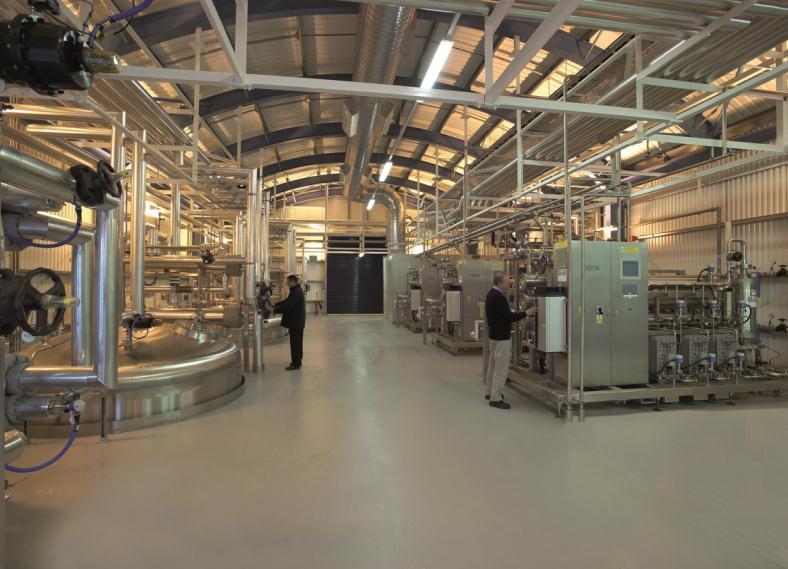
25 VEOLIA Turnkey PW Plant

26 Case Study BELGIUM Sheet 1/5 Scope of Supply: PW Generator Unit 3* Orion 6000 TTS PW Flow Rate: 5,7m³/h With ZWD and Energy saving Concept. PW specifications more stringent than USP Requirements Delivered in 2013


27 Case Study BELGIUM Sheet 2/5 RWD and High Quality Water Recirculation Concept

28 Case Study BELGIUM Sheet 3/5 The Results - Consumptions


29 Case Study BELGIUM-Sheet 4/5 The Results Carbon Foot Print

30 Case Study BELGIUM-Sheet 5/5 The Results Operationnal Costs
31 Microelectronics Industries What are we talking about? UPW standing for Ultra Pure Water HPW standing for High Purified Water Design case by case according Customer specifications and requirements Most of the time for final cleaning and/or washing production components ( Microprocessors, Si or Ge electronic component, IC, )
32 Microelectronics Industries Typical UPW quality TOC < 0.5 ppb Resistivity to 18.2 mega ohm Boron < 5 ppt Silica < 500 ppt DO < 1ppb Sodium < N.D.(<5ppt) Chloride < N.D. Bacteria < 1 CFU/L
33 Microelectronics Industries Addressing typical challenges Cost effective installation Added-value Fast track Large scale project After-sales support Reliability Project build in phase
34 Microelectronics Industries Typical UPW System Pretreatment / Make-up Raw Water Raw water tank Multimedia filters Activated carbon filters RO pre-filters Primary System Two-pass RO Reuse tank Scrubber/ Cooling tower RO product tank TOC UV Membrane degasifier CEDI Primary mixed bed Polishing System Cold DI loop return UPW tank TOC UV Heat exchanger Membrane degasifier Polish mixed bed Cold DI UF Cold DI loop supply Hot DI loop return Recovery HEX Heat exchanger Hot DI UF Hot DI loop supply
35 Microelectronics Industries Design Stringent Process Water s specifications High quality standards for design, equipment and material. Case by case Design Can be compared with the philosophy of the Pharma World Exception for the selected material of the storage and distribution section ( No SS; preference for PVDF and or PP)

36 Microelectronics Industries Case Study BELGIUM Scope of Supply: HPW Generation, storage and distribution 2* HPW generators D&B at 4 m³/h Tech: Soft./Filtration/ph Correction/RO/CDI/UV 3 * Storage and distribution m³/h Fine filtration DI bed UV Material : PVDF Delivered in 2001


37 Microelectronics Industries Case Study Singapore UPW treatment plant Design & construction of UPW treatment plant. Veolia Water BOT contract Capacity makeup: 111m³/h, polishing plant: 4 x 37m³/h, CEDI- VNX: 120m³/h Use of Aquamove TM MORO during the commissioning of the project, 24 m3/hr Technology: ACF, MMF, RO, CEDI-VNX Delivered in 2007 Singapore
16 78 16 20 +32 (0)16 78 16 29 infovwstb@veoliawater.com www.")
38 Imec Veolia 17 march 2014 Thanks for your Attention Your Contacts: General: Pharma and Microelectronic: Veolia Water Solutions & Technologies Belgium Esperantolaan 5 B-3300 Tirlemont +32 (0) (0) infovwstb@veoliawater.com