Arindom Goswami Technical Professional Leader M.W.Kellogg Ltd Greenford, UB6 0JA, U.K.
|
|
|
- Briana Gillian Walsh
- 5 years ago
- Views:
Transcription
1 Power Recovery in Floating LNG Regasification Plants Arindom Goswami Technical Professional Leader M.W.Kellogg Ltd Greenford, UB6 0JA, U.K. Hans E. Kimmel Executive Director R&D Ebara International Corporation Sparks, NV 89434, USA KBR Paper 2218


2 Arindom Goswami is Senior Principal Engineer at M.W. KelloggLtd,U.K.andreceivedin1995aBachelorDegree (Hons) in Mechanical Engineering. With his technical expertise in Rotating Equipment and his global management skills, he contributed to the success of many upstream Oil & Gas projects, including numerous LNG projects. Hans E. Kimmel is Executive Director for Research and Development at Ebara International Corporation. He holds a Master Degree in Mechanical and Process Engineering and a PhD from Munich, Germany. His main contributions are primarily in the LNG technology.


3 Ebara International Corp. p Sparks, NV 89434, USA M. W. Kellogg Ltd Greenford, UB6 0JA, U.K.
4 FSRU the Floating Storage Regasification Units, FPSO the Floating Production, Storage and Offloading Units, FDPSO the Floating Drilling, Production, Storage and Offloading Units are floating vessels used by the offshore industry for the drilling, processing, storage and transportation of LNG and for offloading the cargo in gaseous form at the destination.
5 Keppel Offshore & Marine Ltd Keppel Offshore & Marine Ltd FSRU Golar Winter Floating Storage and Regasification Unit for Golar LNG, Norway
6 Keppel Offshore & Marine Ltd FPSO Espirito Santo Floating Production and Offloading Vessel for Petrobras, Brazil
7 Keppel Offshore & Marine Ltd Keppel Offshore & Marine Ltd World First FDPSO Azurite Floating Drilling, Production, Storage and Offloading Vessel
8 FSRU The LNG is vaporized in a regasification unit on board the vessel using ocean water or natural gas as the heat source. Due to the large temperature difference between the LNG and the environment, a substantial power recovery is suggested. This paper proposes and describes a modified Rankine Cycle to recover efficiently power from the floating regasification plant. The power recovery is achieved using field proven rotating and non-rotating equipment.
9 Even though the offshore regasification process is similar to the onshore process, the design of an offshore plant shows significant differences. Every square meter of an offshore footprint is relatively expensive since it requires the support of an offshore structure. The design has to be compact to keep the surface area as small as possible. Due to the limited space, additional risk mitigation measures and HAZOP assessments are required.
10 The continuous motion of the vessel impacts the design of the process equipment to be able to operate under these dynamic conditions. Rotating equipment has to be designed to withstand the additional gyroscopic forces caused by the vessel movements. The required design of any equipment is such that the center of gravity is as low as possible to increase the stability of the vessel.
11 The conventional regasification process for onshore and offshore plants incorporates two major equipment: The high-pressure send-out pump, to pump the LNG from storage through the vaporizer and up to the high pipe line pressure The vaporizer, to transform the LNG into gaseous natural gas The proposed regasification process incorporates a third equipment, the power recovery system to partially regain the input energy used in the overall process.


12 Cryogenic high-pressure LNG pumps pressurize the fluid up to the high pipe line pressure while it is still in the liquid state
13 Pump General Design Criteria Liquid Model LNG 6ECC-1212 Pump Design Pressure [bara] Lowest Design Temperature [ C] -168 Operating Temperature [ C] -147 Rated Flow [m³/hr] 287 Rated Differential Head [m] 2396 Design Specific Gravity.417 Maximum Specific Gravity.451


14 Typical dimensions for high-pressure LNG pumps: 4 meters in height 1 meter in diameter 12 pump stages with 300 mm impeller diameter


15 Particular design features for high-pressure LNG pumps: Single piece rotating shaft with integrally mounted multi-stage pump hydraulics and electrical induction motor Thrust balancing mechanism to eliminate high axial thrust forces on the bearings Electrical induction motor is submerged in and cooled by LNG Ball bearings are lubricated and cooled by LNG
16 Power Recovery LNG regasification plants are large heat sinks that require large heat sources. The differences in temperatures between the heat sources and the heat sinks are in the range of 170 Celsius providing the pre- conditions for an efficient power recovery. The Rankine Cycle is a thermodynamic cycle which converts The Rankine Cycle is a thermodynamic cycle which converts heat into work. The heat is supplied externally to a closed loop with a particular working fluid, and requires also a heat sink. This cycle generates about 80% of all global electric power.
17 Power Recovery using a Rankine Power Cycle The ideal Rankine Cycle consists of the following o four processes: 1 2 Isentropic compression to high pressure in a pump 2 3 Constant high pressure heat addition in a boiler 3 4 Isentropic expansion in a turbine expander to low pressure 4 1 Constant low pressure heat rejection in a condenser
18 Rankine Power Cycle with vapour expansion
19 Rankine Cycle with liquid-vapour two-phase expansion
20 Thermodynamic Efficiency of the Rankine Power Cycle Specific work input to pump: w in =h 2 h 1 Specific work output from expander: w out = h 3 h 4 Specific heat input from 2 to 3: q in = h 3 h 2 Net power output: w net = w out w in The thermodynamic efficiency e cy of the ideal cycle is the ratio of net power output to heat input. η therm = w net /q in η therm = 1 (h 4 h 1 )/(h 3 h 2 )
21 T - expander turbine P - pump G - generator Schematic of Rankine Cycle with two-phase expansion
22 Schematic for Power Recovery Using Common Working Fluids with a Pump Two-Phase Expander Generator For the Rankine cycle power recovery in LNG regasification plants several field proven working fluids are available and used in similar applications. To achieve a higher efficiency the working fluid is passed through two heat exchangers and one set of a pump two-phase expander generator, a compact assembly of a pump, a two-phase expander and an induction generator integrally mounted on one rotating shaft.
23 Schematic Description with Rankine Power Cycle 1 2 With work input, the pump pressurizes the liquid single phase working fluid from low pressure to high pressure 2 3 The pressurized working fluid is heated by passing through the generator and the heat exchanger with the heat provided by sea water or other heat sources 3 4 The pressurized and heated working fluid expands from high pressure to low pressure across the two-phase expander generating a work output 4 1 The low pressure working fluid passes through a heat exchanger with the heat sink, the LNG for re-gasification. The working fluid condenses from liquid-vapor two-phase to liquid single phase.
24 The compact assembly of a Pump Two-Phase Expander Generator consists of a pump, p a two-phase expander, and an induction generator integrally mounted on one rotating shaft.
25 During start-up of the compact assembly the induction generator operates as induction motor below the synchronous speed. When the shaft power of the expander is greater than the shaft power of the pump then the induction motor operates in the generator mode above the synchronous speed.


26 Pump Two-Phase Expander Generator Working fluid enters the pump at the lower inlet nozzle, exits the pump to the side and passes through the generator housing cooling the generator, thus recovering the heat losses of the generator. After passing through the heat exchanger with the heat source, the working fluid expands across the twophase expander generating work driving the pump and the induction generator
27 Pump Two-Phase Expander Generator In this modified design, the pressurized fluid passes directly from the pump through the generator housing cooling the generator, then exits to the side and pass through the heat exchanger. In both designs, the leakage through the seal and the thrust is minimized due to equal pressure on both sides of the seal and opposing directions of the thrust forces.
28 Advantages of the compact assembly The expander work output is larger than the pump work input and thedifferenceinworkisconvertedby the generator into electrical energy The losses of a separate pump motor are eliminated The losses of the induction generator are recovered and used as heat source to heat the working fluid in addition to the heat from sea water and other heat sources Any leakage of the working fluid is within a closed loop and occurs only between pump and expander
29 Advantages continued Any leakage of the working fluid is minimized due to equal pressure on both sides of the seal, and small leakages are within a closed loop and occur only between pump, expander and generator. The axial thrustt is minimized i i due to opposing directions of the thrust forces decreasing the bearing load and increasing the bearing life.


30 Existing Field Proven Two-Phase Expanders Cross section of a Two-Phase Liquefied Gas Expander inside pressurized containment vessel with lower inlet and upper outlet nozzle Rankine power cycle 3 4 Isentropic two-phase expansion so to a lower pressure

, jet")


31 Two-Phase hydraulic assembly with nozzle ring (red), turbine runner (yellow), jet exducer (green) and two-phase draft tube (metallic) 3 4 Isentropic two-phase expansion to a lower pressure
32 Nozzle Ring with converging nozzles generates high-velocity vortex flow
33 Reaction turbine runner converts angular fluid momentum into shaft torque
34 Jet Exducer A radial outflow turbine for power generation by isentropic two-phase expansion to lower pressure


35 Two-Phase Expander Draft Tube for pressure recovery


36 Field Experience with Liquefied Gas Two-Phase Expanders Two-phase rich liquid feed expanders installed in 2003 are operating successfully at PGNiG, Odalanów, Poland. Additional two-phase expanders are installed in the feed to the lower column during 2009.


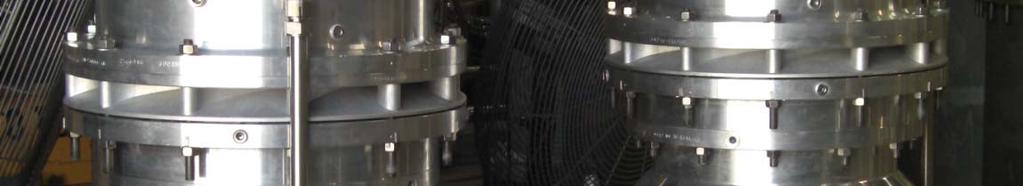
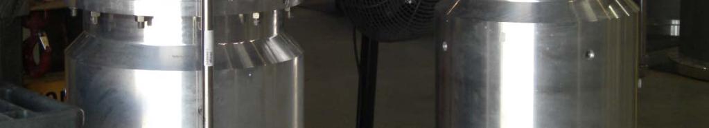
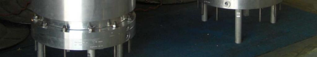

37 Two-Phase Liquefied Gas Expander at Stage Manufacturing
38 The presented Rankine Power Cycle, incorporating a compact design consisting of a pump, a two-phase liquefied gas expander and an induction generator, integrally mounted on one single rotating shaft, offers an efficient and economical power recovery for floating LNG regasification plants
39 Thank You for your attention 謝謝您的關注