--... _ 2-- I I J: 3 4 /
|
|
|
- Terence Joshua Powers
- 5 years ago
- Views:
Transcription


1 _ 3 I I J: 4 /
: 35000 mg/l All mg/l values as ion (not CaCO 3 ) Sea water has little of")

2 Sea Water Composition Typical Sea Water Values Cations mg/l Na + 10,732 Mg ++ 1,297 Ca K Anions mg/l Cl 19,337 SO 4 2 2,705 HCO Br 66 Total Dissolved Solids (TDS): mg/l All mg/l values as ion (not CaCO 3 ) Sea water has little of bicarbonate and silica The density of sea water is between and g/l The ph value of sea water is always between 7.5 and 8.4. The density of sea water is between and g/l. The conductivity of sea water is about 50 ms/cm (50' C.
3 Technical Features & Data Table 1: Systems Models & Typical Flow rates Model Feed Water (m 3 /hr) Open Intake Product Water (m 3 /day) Reject (m 3 /hr) Feed Water (m 3 /hr) Beach Well Product Water (m 3 /day) Reject (m 3 /hr) M RO L2 4040SW M RO L2 4040SW(ERD) M RO L4 4040SW M RO L4 4040SW(ERD) M RO L2 8040SW M RO L4 8040SW M RO L4 8040SW(ERD) M RO L6 8040SW(ERD) M RO L8 8040SW(ERD)
4 Technical Features & Data Table 2: Pretreatment sizes & pump models Model FRP Pressure vessels Media Quantity Pump Diameter Height Quartz (kg) Anthracite (kg) Model M RO L2 4040SW Danfoss (APP1.5) NA M RO L2 4040SW(ERD) Danfoss (APP2.5) Danfoss (APM2.0) M RO L4 4040SW Danfoss (APP1.5) NA M RO L4 4040SW(ERD) Danfoss (APP1.5) Danfoss (APM1.2) M RO L2 8040SW Danfoss (APP5.1) NA M RO L4 8040SW Danfoss (APP6.5) NA M RO L4 8040SW(ERD) Fedco (MSS 1536) Fedco (HPBe 10) M RO L6 8040SW(ERD) Fedco (MSS 1537) Fedco (HPBe 10) M RO L8 8040SW(ERD) Fedco (MSS 1530) Fedco (HPBe 20) ERD 11
 Product TDS (mg/l) ph TDS (mg/l) ph All Models 34,000 ~ 36,000 7.6 ~ 8.4 < 300 6.5 ~ 6.")
5 Technical Features & Data Table 3: Estimated Power Consumption Model Model Table 4: Product Water Qualities Achieved Power Consumption (kwh/m 3 product water ) Open Intake Beach Well Current Seawater Power Source : 415V, 50Hz /60Hz 3 Phase+Neutral+Earth Cable Size (5 Core) Product TDS (mg/l) ph TDS (mg/l) ph All Models 34,000 ~ 36, ~ 8.4 < ~ 6.8 Operating Power (kwh) Open Intake Beach Well M RO L2 4040SW A 4.0 mm M RO L2 4040SW(ERD) A 4.0 mm M RO L4 4040SW A 4.0 mm M RO L4 4040SW(ERD) A 4.0 mm M RO L2 8040SW A 10 mm M RO L4 8040SW A 16 mm M RO L4 8040SW(ERD) A 16 mm M RO L6 8040SW(ERD) A 16 mm M RO L8 8040SW(ERD) A 25 mm
6 Technical Features & Data Table 5: Specifications, Layout and Approximate Dimensions Model Product Water Capacity (m 3 Dimension (mm) Connection (ANSI Flange) /day) Open Beach Well L H W Feed Product Reject Intake M RO L2 4040SW ½ " ¾ " 1" M RO L2 4040SW(ERD) ½ " ¾ " 1" M RO L4 4040SW ½ " ¾ " 1" M RO L4 4040SW(ERD) ½ " ¾ " 1" M RO L2 8040SW " 1" 1 ½ " M RO L4 8040SW " 1" 1 ½ " M RO L4 8040SW(ERD) " 1" 1 ½ " M RO L6 8040SW(ERD) " 2" M RO L8 8040SW(ERD) ½ " 2"

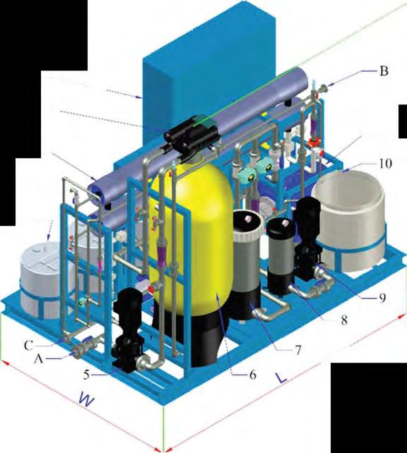
 8 Cartridge filter (flush/cip) 9 Flush/CIP pump 10 Flush/CIP tank 11 High")
7 Table 6: General Assembly Technical Features & Data Utility Connections A B C Feed Product Reject Key Parts & Components Flange Connection Standard ANSI 1 Control panel 2 Multiport valve 3 RO vessel c/w RO membrane 4 Chemical tank 5 Feed pump 6 Multimedia filter tank with coagulant injection system 7 Cartridge filter (service) 8 Cartridge filter (flush/cip) 9 Flush/CIP pump 10 Flush/CIP tank 11 High pressure pump


8 Design Process Process Flow Diagram 15


9 Design Process Pre Treatment Chemical Dosing The raw seawater is supplied to an appropriate pre treatment system by RO feed pump. In order to facilitate a good SDI reduction, strong antimicrobial agent and a coagulant will be dosed upstream. Ferric Chloride (FeCl 3 ) coagulant will destabilize the suspended solids rapidly and increases the removal efficiency of Dual media filtration Sodium Hypochlorite (NaOCl) will cease the growth of microorganism on the inner pipe walls Pre Filtration Dual media filtration system consisting of anthracite and quartz will increase filtration time and water quality respectively by removing color, smell, organics and large suspended solids. Equipped with differential pressure switch and Multiport valve (MPV) for automatic backwash either on periodic basis or when a certain pre set differential pressure kicks in.


10 Design Process Pre treatment Chemical Dosing Sodium bisulphite a dechlorination agent should be injected upstream of cartridge filter to initiate the reduction of free chlorine. The resultant Sodium bisulphate will be removed by cartridge filter a secondary filter RO Operation RO separation is a pressure driven process, being said that the external pressure shall be provided by RO high pressure pump. The pressure transmitters are located at critical upstream and downstream points of the pump to constantly monitor the pressure and send back the real time data to the data logging unit. The pressurized water will flow through spirally wound RO membranes, the place of actual separation process. An online conductivity transmitter will be used to monitor the conductivity of permeate and offspec, as the latter being a water with higher conductivity than a specified range. Antiscalant to minimize the scale formation and frequent cleaning of RO membrane

11 Design Process RO Operation Energy Recovery Device The use of an ERD (integral with the high pressure pump), transmits the brine pressure back to the high pressure pump shaft, thus reducing energy required to pressurize the seawater feed through the RO membranes. The flexibility in the designs and configuration of our standard SWRO systems allow installation of the ERD on selected models.


12 Control & Instrumentation Features Touch screen HMI for easy optimization at site and entry of process parameters Programmable Logic Controller Download trend, history, faults, alarms via thumb drive High efficiency EFF1 pumps VSD driven for all pumps Integrated CIP facility
13 Consumables Model Chlorine (12.5% Cl 2 ) Chemical dosing Systems Cartridge filter RO Membranes Antiscalant Use Rate for 1 year SMBS (Powder) Coagulant (Optional) RO30 CIP20 1 st yr 2 nd yr 3 rd yr M RO L2 4040SW 32kg 36kg 12kg 100kg 12pcs 12pcs 1 pc 1 pc M RO L2 4040SW(ERD) 32kg 36kg 12kg 100kg 12pcs 12pcs 1 pc 1 pc M RO L4 4040SW 44kg 44kg 16kg 132kg 20pcs 16pcs 1 pc 2 pcs 1 pc M RO L4 4040SW(ERD) 44kg 44kg 16kg 132kg 20pcs 16pcs 1 pc 2 pcs 1 pc M RO L2 8040SW 120kg 120kg 46kg 384kg 32pcs 20pcs 1 pc 1 pc M RO L4 8040SW 152kg 144kg 58kg 480kg 32pcs 20pcs 1 pc 2 pcs 1 pc M RO L4 8040SW(ERD) 152kg 144kg 58kg 480kg 36pcs 20pcs 1 pc 2 pcs 1 pc M RO L6 8040SW(ERD) 268kg 264kg 102kg 852kg 36pcs 24pcs 1 pc 3 pcs 2 pcs M RO L8 8040SW(ERD) 296kg 288kg 112kg 936kg 36pcs 28pcs 2 pcs 4 pcs 2 pcs
14 Process & Instrumentation Drawing M RO L2 4040SW
15 Process & Instrumentation Drawing M RO L2 4040SW ERD
16 Process & Instrumentation Drawing M RO L4 4040SW
17 Process & Instrumentation Drawing M RO L4 4040SW ERD
18 Process & Instrumentation Drawing M RO L2 8040SW
19 Process & Instrumentation Drawing M RO L4 8040SW
20 Process & Instrumentation Drawing M RO L4 8040SW ERD
21 Process & Instrumentation Drawing M RO L6 8040SW ERD
22 Process & Instrumentation Drawing M RO L8 8040SW ERD