Uncertainty Analysis of Otway CO2 Sequestration Project
|
|
|
- Shon Damian Hubbard
- 5 years ago
- Views:
Transcription
1 Uncertainty Analysis of Otway CO2 Sequestration Project Shohreh Amini 1,2, Shahab D. Mohaghegh 1,2,, Razi Gaskari 3, Grant Bromhal 1 ( 1 National Energy Technology Laboratory-Regional University Alliance (NETL-RUA), 2 West Virginia University, 3 Intelligent Solutions Abstract A viable means of CO2 reduction in the atmosphere is to capture and concentrate CO2 from large point sources such as power plants and petroleum refineries and store it by underground injection. The main concern for commercial scale CO2 sequestration in geologic formations is the uncertainties associated with this process. The risks involved in different stages of a CO2 sequestration project are related to geological and operational uncertainties. This paper presents the application of a grid-based Surrogate Reservoir Model (SRM) to a real case CO2 sequestration project in which CO2 were injected into a depleted gas reservoir. This project is a part of the National Risk Assessment Partnership (NRAP) s research on CO2 sequestration process. An SRM is a customized model that accurately mimics reservoir simulation behavior by using Artificial Intelligence & Data Mining techniques. Initial steps for developing the SRM included constructing a reservoir simulation model with a commercial software, history matching the model with available field data and then running the model under different operational scenarios or/and different geological realizations. The process was followed by extracting some static and dynamic data from a handful of simulation runs to construct a spatio-temporal database that is representative of the process being modeled. Finally, the SRM was trained, calibrated, and validated. The most widely used Quantitative Risk Analysis (QRA) techniques, such as Monte Carlo simulation, require thousands of simulation runs to effectively perform the uncertainty analysis and subsequently risk assessment of a project. Performing a comprehensive risk analysis that requires several thousands of simulation runs becomes impractical when the time required for a single simulation run (especially in a geologically complex reservoir) exceeds only a few minutes. Making use of surrogate reservoir models (SRMs) can make this process practical since thousands of SRM runs can be performed in minutes. Using this Surrogate Reservoir Model enables us to predict the pressure, phase saturation, and CO2 distribution throughout the reservoir with a reasonable accuracy in seconds. Consequently, uncertainties associated with reservoir characteristics and operational constraints are analyzed with the SRM in a considerably shorter amount of time compared to the conventional uncertainty analysis techniques. Surrogate reservoir modeling opens new doors in reservoir modeling by providing the means for extended study of reservoir behavior with very low computational cost. Introduction Despite all the efforts in shifting the energy sources to the renewable and atmosphere friendly source of energy, fossil fuels are still the most essential source of energy for industries and transportation. Considering the demand growth it is believed that fossil fuel consumption will continue to increase through the next century. As a result, concerns about the greenhouse gas emission and its impact on global warming and climate change are increasing. This has encouraged focus on two different approaches of reducing CO2 in the atmosphere. The first one is the preventive methods which aim at 1
2 minimizing CO2 emission in to the atmosphere through improved efficiency, renewable energy supplies, carbon-free fuel consumption and nuclear fission, and the second approach is to apply the remedial methods through which the CO2 concentration in the atmosphere is reduced [1,2]. A viable means of CO2 reduction in the atmosphere is to capture and concentrate CO2 from large point sources such as power plants and petroleum refineries and store it by underground injection. The process is called Geological Carbon Sequestration (GCS). Three types of target reservoirs are capable of sequestering large volumes of CO2 which are depleted oil and gas reservoirs, saline aquifers and coal beds. In these reservoirs, high pressure and temperature make CO2 a supercritical state in which CO2 acts as a liquid. Therefore, it would be possible to inject a large volume of CO2 into a limited pore volume of reservoir [3]. The main concern of commercial scale CO2 sequestration in geologic formations is the uncertainties associated with this process which is directly related to the geological and operational uncertainties of the process. Since the CO2 is injected underground there is no direct method to determine the CO2 flow in the porous media. The reservoir simulation models are the only tools through which the CO2 fate can be studied. These models are constructed based on the geological studies and interpretations, field observation and measurements and therefore are essentially uncertain. In each specific sequestration project, different operational practices will have different sequestration outcomes. Consequently, any practical uncertainty analysis and risk assessment technique should address both geological and operational uncertainties. The most widely used uncertainty analysis techniques, such as Monte Carlo simulation, require thousands of simulation runs for implementing a comprehensive uncertainty analysis for a specific CO2 sequestration project. In creating the reservoir simulation models on one hand adding complexity to the reservoir simulation model is inevitable since integrating all the observations and measurements is the sensible way to reduce the uncertainty and on the other hand the more complex the simulation model, the higher the run time. Therefore, using the conventional geo-statistical approach for uncertainty analysis of a fairly complex reservoir needs thousands of simulation runs makes it impractical. Other conventional method that is currently used for uncertainty analysis is generating a Response Surface for the problem. Response Surface Methodology (RSM) is a collection of statistical and mathematical techniques useful for developing, improving, and optimizing processes [4]. The field of response surface methodology consists of the experimental strategy for exploring the space of the process or independent variables, empirical statistical modeling. It develops an appropriate approximating relationship between the output and the process inputs [5]. In order to develop a Response Surface for uncertainty analysis, several combinations of the input parameters (chosen from a reasonable range) are generated and hundreds of simulation runs outputs are provided through making different realizations in a reservoir simulator. Using the outputs from simulation runs and based on some mathematical methods, a surface is generated to represent the possible responses which is resulted from the predetermined realizations. Different realizations are selected so that maximum coverage is obtained with minimum simulation runs. Some other techniques are used such as Latin Hyper Cube and Design of Experiments in order to optimize this process [6, 7]. Generally, the geo-statistical approaches such as those explained above suffer from major shortcomings such as: 1. They still need hundreds of simulation runs to be capable of effectively perform a comprehensive uncertainty analysis. 2. Once the simulation runs for all realizations were completed, the response surface is generated 2

3 using the outputs and thus the input parameters no longer play any role. In other words, it would not be possible to evaluate the output if any of the inputs are to be changed to the value that does not exist in the developed realization. In this study, we are making use of the Surrogate Reservoir Modeling (SRM) technique [8] for uncertainty analysis of a real CO2 sequestration project. This technique is not based on statistics and therefore just needs a handful of reservoir simulation runs in order to perform the required analysis. SRM is a customized model that mimics reservoir simulation results by using Artificial Intelligent & Data Mining techniques with a very low computational cost. It consists of one or several neural networks which are trained, calibrated and verified using very small portion of data. SRM can be constructed as well-based or grid-based. Well-based SRM is able to make predictions for the well parameters such as rate of oil, gas and water production [9, 10] and the grid-based SRM will return the grid level parameters such as pressure and liquid/gas phase saturation. One of the other advantages of SRM is that once an SRM is created for a specific problem, the input parameters can be changed (within a range) at any time and the output response to this change can be observed and evaluated. Moreover, the impact of any input alteration on the output is obtained within a few minutes regardless of the complexity of the reservoir model [9]. Field Background The current work is based on a real CO2 sequestration project in a depleted gas reservoir. The field is located in Otway Basin in Victoria, Australia. The location of the field is depicted in Figure 1. The target reservoir for injecting CO2 is Waarre-C formation, which is a sandstone reservoir of about 100 ft thick located at about 6561 ft underground with an area of about 500 acres. The reservoir has an average porosity and permeability of 18% and 1000 md respectively. The structure is bounded with three major sealing faults and two aquifers which are connected to the reservoir from south-east and west side. Figure 1. Otway Field Location in Victoria, Australia (Reference: IEA Greenhouse gas R&D program website) Three wells were drilled in this field. The first well, Naylor South-1 was a dry hole but it provided useful stratigraphic information of the reservoir. The second well (the only production well) was drilled in 2002, and started producing natural gas from May 2002 until October 2003 and was converted to a CO2 monitoring borehole in The CO2 injection well (CRC-1), was drilled in 2007 approximately 1000 ft away from the producing well and CO2 injection started at March

4 In this project, CO2-rich gas that contains about 80% CO2 and 20% methane is produced from Buttress-1 well in a nearby gas field then compressed, transported along the existing 1.25 mile pipeline to the site and injected in to a depleted gas reservoir at a depth of 6561 ft [11, 12]. Methodology Conventional Reservoir Simulation Model Developing a numerical simulation model for this process is the only means to evaluate the consequences of CO2 injection in to the reservoir under different operational practices while the constraints and limitations are respected. Moreover, it provides us with the required data at the grid block level which is then used to construct the Surrogate Reservoir Model. In this study, a numerical reservoir simulation model was constructed in CMG-GEM which consists of 100x100x10 Non-Orthogonal grid blocks. In order to make the structural map of the reservoir, an available contour map of the reservoir top was used and a uniform thickness of 100 ft was assigned to the entire structure. The reservoir structure and the well locations are shown in Figure 2. Figure 2. Reservoir Structure Constructed in CMG The available core and log data from CRC-1 well and some other geological factors were employed to generate the porosity and permeability maps throughout all 10 layers of the reservoir based on statistical methods. The initial reservoir pressure was specified as 2872 psi at the reference depth of 6562 ft and the reservoir temperature was considered as 185 F. Two existing aquifers were modeled using Carter-Tracy modeling method. Based on the completion data the production well was perforated in layers 2 and 3. The available natural gas composition and the experimental relative permeability curve including the hysteresis effect were used to define the production fluid and the rock-fluid interaction correlation. The injection well was perforated along the interval of to ft during drilling and then it was extended to the interval of to ft. Therefore, this well was perforated in five layers of the reservoir (layer 3 to 7). A composition of 80% CO2 and 20% CH4 was considered as the injection fluid and the same relative permeability curve was used in the injection phase. Since there is a water table and an active aquifer system, a fraction of the injected CO2 is certainly dissolved in to the water phase. In order to model the CO2 solubility, a fluid model was generated in WinProp enabling CO2 to dissolve into the water phase and it was then imported to the main model. 4
5 This model was history matched based on the available field data in both natural gas production and CO2 injection phases. The production rate (18 months) and the injection rate (8 months) were considered as the constraint in the model and the well bottom-hole pressure was matched for Naylor-1 and CRC-1 wells. Figure 3 shows the result of history matching for both production and injection wells. Figure 3. History Matching the Bottom-Hole Pressure of the Production and Injection Well It should be mentioned that since our focus is on the CO2 injection and sequestration, the natural gas production phase is just used for the history matching purpose in the reservoir simulation model and no data from this phase is used in SRM development process. As mentioned before, just a few simulation runs are sufficient to provide data for making a Surrogate Reservoir Model. The simulation runs are designed based on the objectives of the study. This work focuses on the uncertainty associated with the operational constraint and geological realization of the sequestration project and therefore, the simulation runs are designed so that they take into account both areas of concern. Considering the real case CO2 injection as the base model, five other injection scenarios are designed. In two of them, the behavior of the system is investigated when higher amount of CO2 is injected over the same injection interval (with respect to the base model) and in others, the impact of CO2 injection over longer injection period is observed. In order to take into account the geological aspect, all the mentioned scenarios are run for two different geological realizations. Surrogate Reservoir Model To construct a grid-based SRM, an inclusive spatio-temporal data base was generated based on the 12 simulation runs. This database contains the well data, static data and dynamic data of all grid blocks of the reservoir. The well data consists of the time dependent well parameters such as injection rate or well bottom-hole pressure. The static data includes the reservoir characteristics (porosity, permeability, etc), grid block coordinates and some other data that represents the position of the grid block in the entire system such as the distance of each grid block to the injection well, to the boundaries and to aquifers. Finally, the pressure, phase saturation and CO2 mole fraction in different phases at each time step are collected as dynamic parameters. In the database, we also included the same data from the adjacent grid blocks of each grid. 5


6 Subsequently a very small portion of data was selected from the entire database. Note that, data selection should be properly performed to ensure that the selected data are an adequate representative of the entire grid blocks in the reservoir. Therefore, all the grid blocks in the reservoir were categorized to eight different grid types according to their location in the reservoir structure which are: aquifer corner, nonaquifer corner, sealing boundary, aquifer boundary, next to aquifer boundary, completed and next to completed and finally all other grid blocks. Accordingly, a reasonable amount of data was selected out of all categories. In this work, only 1% of the entire data was randomly selected for creating the grid-based SRM. The selected data is arranged in a specific format in order to be used as input to neural networks which will be integrated as SRM. This input file was used to construct several artificial neural networks for each of the dynamic parameters of interest which are pressure and CO2 mole fraction of the reservoir grid blocks in this work. Back Propagation training method was used in which the error is feed backed to the network by the end of each training epoch [13]. All the networks contain one hidden layer and one output. The networks are trained, calibrated and verified using the selected data. During the training process the performance of the neural networks in predicting the output parameter can be investigated by observing the cross plots of the predicted versus simulation output data and the calculated R-square value. The cross plots of the predicted value versus reservoir simulation output for some of the pressure and CO2 mole fraction networks in verification set are presented in Figure 4 and Figure 5. Figure 4. Cross plot of SRM predicted versus simulation output for Pressure in verification set (Network A, left Network B, right) Figure 5. Cross plot of SRM predicted versus simulation output for CO2 mole fraction in verification set (network A, left network B, right) 6
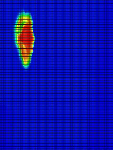
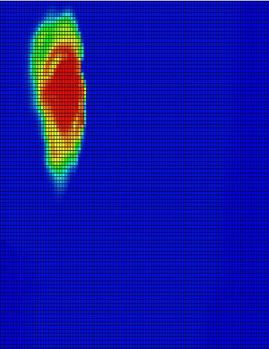
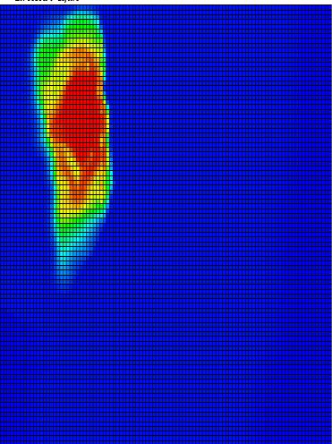
7 Subsequently, SRM was created by integrating all these neural networks when the training process was accomplished. The existing SRM is able to predict the model output at each time step (t) providing the parameters at previous time step (t-1). This makes the predictions at each time step to be dependent on the simulation outputs of the previous one. Therefore, one further step is needed to eliminate this dependency. This process is called Cascading, through which at each new time step the predicted value of the previous time step is used as the (t-1) value to make the predictions for the dynamic parameters at current time step (t). Therefore, the only value of the dynamic parameter which is used within this process, is the initial value of these parameters. Results The constructed SRM is able to mimic the reservoir simulation outputs with a reasonable accuracy for all grid blocks of the reservoir when it is applied to each scenario individually. In order to evaluate the SRM result in predicting the output parameters, the prediction results were visualized as 2-D distribution maps for pressure and CO2 mole fraction for all 10 layers of the reservoir and it was compared to the simulation output. As a sample the distribution maps of these two parameters in layer 1 of the reservoir after 4, 6 and 8 month of injection are shown in Figure 6 and 7. To this point, it was shown than the Surrogate Reservoir Model is able to predict the dynamic parameters of the reservoir grid blocks with a very good accuracy compared to the reservoir simulation output. In order to address the two types of uncertainty (geological realization and operational constraint) in this project by using SRM, first two different geological realizations for permeability and porosity was generated for the reservoir. The original porosity and permeability maps and the new realizations for the first layer of the reservoir are presented in Figures 8 and 10. SRM was run under these two realizations to investigate the changes in CO2 mole fraction in the reservoir. Note that this process is performed by just changing the value of the corresponding parameters in the input file and simply run the SRM in few minutes to obtain the results of any dynamic parameters in each grid block at each time step. The results of the SRM in predicting CO2 mole fraction distribution in layer 1 of the reservoir in three months under the two geological realizations can be observed in Figure 9 and 11. In the next step, the performance of SRM under different injection schedule was investigated. The new schedule was assigned as 1.5 times the real case total CO2 injected (890 MMSCF) within 3 times the real case injection interval (24 months). The results of CO2 mole fraction distribution in the first layer of the reservoir after 8, 16 and 24 months of injection is shown in Figure 12. Conclusion This study has shown that the Grid based SRM is capable of replicating the results of a complex numerical simulation models with a reasonable accuracy. This methodology uses state of the art data mining and Artificial Intelligence for comprehensive search of the solution space associated with the numerical simulation models. The process of uncertainty analysis can be performed very efficiently by using SRM since it can be run in a considerably shorter amount of time compared to the conventional reservoir simulation. Acknowledgements This work was performed in support of the National Risk Assessment Partnership (NRAP) s ongoing research in CO2 Sequestration under the RES contract DE-FOA
8 References [1] W.C. Turkenburg, Sustainable development, climate change, and carbon dioxide removal (CDR), Energy conversion and Management, 38S (1997), pp. S3 S12 [2] Bachu, S., Sequestration of CO 2 in geological media: criteria and approach for site selection in response to climate change, Energy conversion and Management 2000: Volume 41: Issue 9: pages [3] CO2CRC Storage Capacity Estimation, Site Selection and Characterization for CO2 Storage Projects, CO2CRC Report No: RPT [4] Myers Raymond H., D.C. Montgomery Response Surface Methodology: process and product optimization using designed experiment, A Wiley-Interscience Publication. [5] Carley, M., Kamneva, N. Y., Reminga, J Response Surface Methodology1, CASOS Technical Report, CMU-ISRI [6] A User s Guide to LHS: Sandia s Latin Hypercube Sampling Software, [7] Douglas C. Montgomery, John Wiley &Sons, Design and Analysis of Experiments, by, ISBN: X [8] Mohaghegh, S. D., Reservoir simulation and modeling based on artificial intelligence and data mining (AI&DM), Intelligent Solutions, Inc. and West Virginia Universities, USA, (Vol 3. December 2011, Pages ) [9] Mohaghegh, S.D., Hafez, H., Gaskari, R., Haajizadeh, M., Kenawy, M Uncertainty analysis of a giant oil field in the Middle East using surrogate reservoir model, Paper SPE , Presented at the International Petroleum Exhibition and Conference, Dhabi, Abu Dhabi, UAE, 5-8 November [10] S.D. Mohaghegh, A. Modavi, H. Hafez, M. Haajizadeh, Development of Surrogate Reservoir Model (SRM) for fast track analysis of a complex reservoir, International Journal of Oil, Gas and Coal Technology, 2 (1) (February 2009), pp [11] Dancea, T., Spencera, L., Xua, J., What a difference a well makes, International Conference on Greenhouse Gas Control Technologies (GHGT-9), November 2008, Washington DC, USA [12] Bouquet, S., Gendrin A., Labregere, D., et al Parameters influencing Dynamic modeling of CO2 Injection into a Depleted Gas Reservoir, Presented at SPE Offshore Europe Oil & Gas Conference & Exhibition, Aberdeen, UK, 8 11 September. [13] D.E. Rumelhart, J. L. McClelland and R. J. Williams, Learning Internal Representation by Propagation Error: Nature, 323: Reprinted in Anderson and Rosenfeld, 1998, pp


 9")
9 Figures July 2008 SRM September 2008 SRM November 2008 SRM July 2008 CMG September 2008 CMG November 2008 CMG Figure 6. Pressure distribution in layer 1 after 4 month, 6 month and 8 month of CO2 injection (above SRM prediction, below CMG output) July 2008 SRM September 2008 SRM November 2008 SRM July 2008 CMG September 2008 CMG November 2008 CMG Figure 7. CO2 mole fraction distribution in layer 1 after 4 month, 6 month and 8 month of CO2 injection (above SRM prediction, below CMG output) 9


10 Figure 8. Porosity distribution in layer 1 (left: original distribution, right: realization 1) July 2008 September 2008 November 2008 Figure 9. SRM prediction of CO2-gas distribution in layer 1 after 4, 6 and 8 months of injection with new porosity distribution (realization 1) Figure 10. Permeability distribution in layer 1 (left: original distribution, right: realization 2) 10


11 July 2008 September 2008 November 2008 Figure 11. SRM prediction of CO2-gas distribution in layer 1 after 4, 6 and 8 month of injection with new permeability distribution (realization 2) After 8 Months After 16 Months After 24 Months Figure 12. SRM prediction of CO2-gas distribution in layer 1 after 8, 16 and 24 months of injection with new injection schedule 11