The expected outcome of utility integrated resource planning (IRP) is the. A Flexible Generation and Energy Storage Solution POWER PLANT OPTIMIZATION
|
|
|
- Emory Shepherd
- 5 years ago
- Views:
Transcription
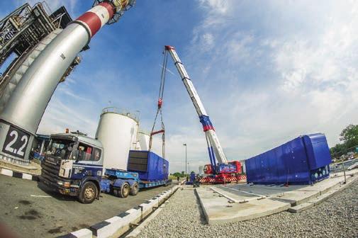
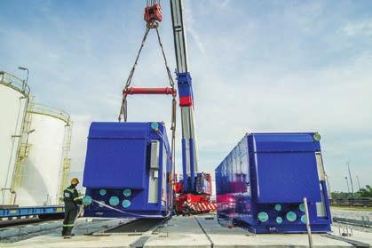
1 Author Peter Perri is vice president of Marketing for Powerphase Each module is completely self-contained in an 8-ft. x 40-ft. sound attenuated enclosure. A gas-fired engine-compressor set produces compressed air that is added to the combustion turbine s compressor discharge section to reduce the effect of a high ambient temperature or altitude performance derate. Photo Courtesy: Powerphase A Flexible Generation and Energy Storage Solution BY PETER PERRI The expected outcome of utility integrated resource planning (IRP) is the optimum combination of power generation resources that will produce the most cost-effective and reliable generation for the rate-payer. That process is relatively simple for a nuclear and fossil fuel-based system. However, the difficult process of integrating renewable generation has made asset optimization and operational flexibility paramount. Reaching that goal is often further complicated by external influences. For example, states/nations with Renewable Portfolio Standards often require a set quantity renewable generation to be produced each year. Others have market-driven rules or have enacted legislation that require placing renewable generation first place in the dispatch queue, thereby pushing conventional assets further down the list, often from baseload to cycling operation. The unpredictability of renewable assets that operate only when the wind blows and the sun shines require more frequent cycling, start/stops, and ramping of assets that accelerates equipment wear-and-tear. Planners have a difficult job optimizing grid efficiency with so many moving parts. All grid operators want more flexible generation that is available on demand. As additional wind and solar generation come online, some grid operators have elected to rely on market mechanisms to entice developers to construct fast response assets to fill in the inevitable production gaps inherent with renewable generation. Others have installed decentralized blocks of gasfired assets, usually simple cycle combustion turbines or reciprocating engine generators, to provide quick response power when needed. Many utilities are forced to keep assets operating a part-load to satisfy rising spinning reserve margins. Many utilities have added flexible generation in the form of high-efficiency combined cycle power plants but they remain best suited for operation at or near baseload operation for maximum efficiency. There is also a steep price to pay in O&M and lost efficiency when cycling or operating a combined cycle plant at partload. The elegant solution is large-scale energy storage but that technology remains a future promise. Often these solutions attempt to use fossil generation in ways it wasn t designed to be used, cycling when renewable energy supplies spike up or down, for whatever reason.

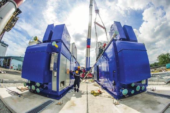
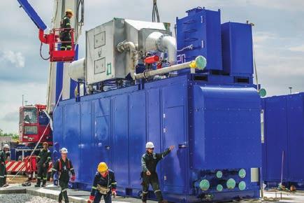
2 This Turbophase system consists of four main components, from back to front: turbocharged natural gas-fired reciprocating engine, gearbox, and multi-stage centrifugal compressor. A single air pipe is run from the outlet of the compressor to the CT. Multiple modules may also interconnected in parallel to provide additional CT power production. Photo courtesy: Powerphase Doing so is a viable short-term solution when large amounts of renewable generation is added to a system but it isn t sustainable and often not economically justifiable. There are more fuel efficient, cost effective, reliable solutions that are better for ratepayers and better for the environment. RETROFIT FLEXIBLE GENERATION Until large-scale energy storage is commercially available, the no-nonsense approach for adding flexible generation is Test Results to extract unused power generation capability from existing combined cycle assets. Jupiter, FL-based Powerphase has commercialized a dry air injection system for existing or new simple or combined cycle combustion turbines. The big idea is to take a combined cycle plant, the most efficient generation asset for any utility, and make it even more efficient, increase its generation capability, and to increase its operational flexibility. There is technology capable of adding up to percent more power to the grid by injecting high pressure and temperature dry air into the combustion turbine (CT) compressor discharge. The result is virtually instantaneous production of the fast response power needs of the modern grid while at the same time increasing unit efficiency and therefore lower cost of service to the ratepayers. The technology is configured with a multi-stage intercooled centrifugal compressor driven by a very efficient turbocharged natural gas- or diesel-fired internal combustion engine that compresses air to the appropriate psi for the specific CT application. The system can be integrated to any new or existing combustion turbine. The air then enters a recuperator that recovers heat from the engine exhaust in order to heat the clean, dry compressed air to about the appropriate temperature before entering the CT compressor discharge section. The added air then flows into the combustor where fuel is added and additional power is produced in the turbine section of the CT GT1 MW TPM1 Full Injection No Injection TPM1 Full Injection No Injection TPM1 Full Injection No Injection TPM1 & TPM2 Full Injection TPM2 Air Compressor Trip GT1 Inlet temperature (F) :30:00 PM 2:00:00 PM 2:30:00 PM 3:00:00 PM 3:30:00 PM 4:00:00 PM 4:30:00 PM 5:00:00 PM 5:30:00 PM 6:00:00 PM Time Source. Powerphase 51
3 For a combined cycle plant, the additional mass flow entering the heat recovery steam generator increases steam production and therefore additional power is also produced in the steam turbine. The net result is an increase in power generation and because the engine-compressor is more efficient than the CT the net combined cycle heat rate is also improved. The CT has unused power generation capability when ambient temperatures or elevations rise and is capable of producing more power but is unable to at elevated temperatures or when installed at elevated sites. The CT compresses air at constant volume so when ambient temperatures rise, less air is compressed and therefore the CT produces less power. The CT power output is proportional to air mass flow through the CT. Turbophase is designed to produce a constant incremental mass flow of air so that design CT power output (usually up to rating of the generator) is produced, regardless of ambient temperature (or elevation). Likewise, the turbocharged gas-fired reciprocating engine turning the air compressor is controlled to produce constant power regardless of ambient temperature or elevation. Therefore, the Turbophase compressed air flow and compressor air flow are proportional and the boost power remains constant. The compressor has much more compressor pressure ratio margin than the CT compressors so CT compressor performance and surge margins are not limiting. The technology injects higher temperature and pressure air (matched to the specific CT compressor discharge conditions) to regain that lost power generation capability irrespective of the ambient conditions (from 32F [-17C] to 122F [50C]) or altitude. The amount of air that can be added is determined by the manufacturer rating of the CT. General Electric, for example, allows 5% mass flow injection into the compressor discharge plenum. Other OEMs have similar published standards. RAPID RESPONSE SYSTEM The flexibility of producing peaking power from an operating plant should be of great interest to grid operators and combined cycle plant owners because the system response is comparable to what the grid experiences from intermittent renewable resources. The response time is dependent on its operating mode. On an operating CT, it can ramp up to produce full air flow in approximately 60 seconds or less. If it is already running at idle then ramp up from part load to full load can take place in 10 seconds or less (Figure 1). The extent of performance gain depends on plant configuration (simple cycle CT or combined cycle) and the number of modules selected. For example, on a 7FA.04 2x1 combined cycle, four modules per CT (total of eight modules) can be used. For this example, the eight modules will produce an incremental increase of ~54MW or about 6.8MW per module in combined cycle mode. H-Class CTs and aeroderivative engines have a greater pressure ratio so additional compression can be achieved by the compressor to accommodate the higher CT compressor discharge pressure, without a change to the standard module footprint (Figure 4). The limiting factor in determining the number of modules that can be added is the CT generator capability. A quick estimate of the number of modules is possible by determining the incremental power output of the generator available at the highest expected site temperature. A typical 7FA can handle meaningful levels of additional power, assuming there are no other power augmentation or upgrades already present on the CT. The economics of the system compares very favorably with other CT power increase technologies. One interesting comparison is an OEM upgrade although the economics are site specific, although the life of the hardware is an estimated 30 years. Another potential option is adding a chiller and thermal energy storage for cooling the air entering the CT. Again, our experience evaluating this alternative is the Turbophase payback is much shorter than the typical system designed to store energy 18 hours/day and discharge 6 hours/day. The system can operate 24/7 in all ambient conditions, does not impose a power penalty on the CT when running as does a chiller, and can start and ramp up to operation in less than one minute. Also, Turbophase modules can be physically moved as market conditions or seasonal conditions dictate. The value as a source of peaking power is substantial. A recent study of the economic impact of adding the system to the generating fleet of a Florida utility determined that the efficiency of the incremental power would displace generation from CT peakers and coal-fired units, saving about $100 million per year and reducing carbon dioxide emissions by over four million tonnes per year. IMPORTANT DESIGN CONSIDERATIONS The system is designed to follow the operation of the CT. For example, should a compressor trip the change in compressed air flow through the CT compressor will be reduced, perhaps as much as 5 percent at maximum flow. The effect of the operation of the CT is minimal. The small reduction of air flow into the combustor will momentarily produce a slightly richer flame that will be sensed by exhaust temperature probes and the fuel control will automatically adjust within about a second. Also, a richer flame reduces the likelihood of a flame out. Combustor flame stability and blow out are caused by reductions in flame temperature, which doesn t occur with a Turbophase shutdown. The system also has little effect on heat recovery steam generator (HRSG) duct burner operation. However, if the steam turbine is flow limited on hot days then the increased air flow through the HRSG will cause a desirable decrease fuel flow to the duct burners. The net effect is improved plant heat rate. For most 7FA combined cycle plants, the duct burner systems are exhaust temperature limited. Since the system reduces the exhaust temperature of the CT (increasing air flow produces increases the turbine pressure ratio), the duct burner capability is actually increased approximately 3 MW for a 25 MW system at no additional capital cost. Another unique advantage is found on

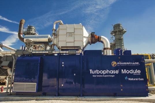
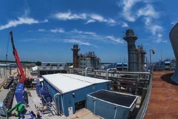
4 A typical 2 x 1 combined cycle plant is illustrated. This plant uses General Electric 7FA combustion turbines, which allows four or more Turbophase modules per turbine. The plant, outfitted with 8 modules, will produce an additional 54 MW. Photo courtesy: Powerphase a 3 x 1 combined cycle plant where two CTs running at minimum load are required to keep the steam turbine operating. The system may provide enough additional steam flow that only one CT may be required to keep the steam turbine synchronized. If so, It will produce a sizable increase in combined cycle efficiency when operating at minimum load. ANCILLARY SERVICES OPPORTUNITIES This technology has an important place in every utility IRP also for its contribution to grid ancillary services, such as synchronized reserve and fast grid regulation services. Synchronized reserve. In our earlier example, a 7FA.04 2x1 combined cycle with eight modules can produce, at high ambient conditions, up to an additional 54 MW (~40 MW at ISO conditions), or about 6.8 MW per module, as mentioned earlier. A small portion for the power increase, perhaps 10%, is produced by the steam turbine. That means the system can quickly put about 36 MW (ISO) on the grid limited only by the CT ramp rate (for example, the GE 7FA ramp rate is 40 MW/minute) with the steam turbine power increase following several minutes later. The competitive option would be a separate standby gasfired engine sitting in hot start conditions that could be synchronized to the grid in about 60 seconds or less and but reaching full load in 90 to 180 seconds. The standby engine will also require a separate generator and switchgear. The system responds faster than a standby engine generator. Fast grid regulation. Turbophase responds to load demand fluctuations that occur within 60 seconds or less. Test data show that an increase in CT output is measured within a minute with the steam turbine following in about 10 minutes. The standard PJM grid response requirement for grid regulation is within 10 minutes. That means that Turbophase-equipped combined cycle plant may qualify for increased ISO or RTO payments for grid regulation power, if offered in your area. It s important to note that the design of Turbophase will never be the limiting factor for plant ramp speed, even with aeroderivative engines, because its controls are tuned to follow the same ramp speed of the CT. ENERGY STORAGE, TOO In addition to flexible generation, another highly desire generation resource is energy storage. While energy storage has been discussed for many years as the holy grail of green energy, very few utility-scale projects have been deployed. As renewable penetration increases, even the addition of flexible generation to the grid will be insufficient to compensate for the lost efficiency and increased cost of cycling fossil fuel plants. The challenge then becomes how to move generation from the time it is produced to the time when the energy is required. For example, there is great economic benefit to operate a gas-fired combined cycle plant at maximum efficiency if the surplus power produced could be stored and then used at precisely the moment that production from renewable energy resources drop. 53
5 Developers have fielded several technologies to answer the problem of renewal intermittency and matching demand and production. Battery storage is one option. In February, AES Energy Storage placed what is touted as the world s largest lithium ion battery system online in Southern California. The plant is capable of delivering 30 MW for four hours before having to be recharged. The stated purpose of the plant is to facilitate integration of more renewable energy to the grid. Not surprising, the cost of the system was not revealed although we do know that energy storage was mandated and incentivized by the California Public Utilities Commission. Another option is compressed air energy storage (CAES). The 317-MW Bethel Energy Center, Anderson County, TX, represents the most modern technology and is expected to enter commercial service in The $400 million CAES plant includes construction of a salt dome for compressed air storage. A third option is pumped storage although the majority of plants in the U.S. were built over thirty years ago and there are only a hand full of projects in the FERC approval queue at the moment. Each of these energy storage options is limited in application, very expensive, or both. Instead of building entirely new energy system, Powerphase has developed a simple method of adding energy storage to existing CTs. The equipment, dubbed, FastLight, offers utilities the benefits of energy storage at a lower cost to ratepayers while, again, leveraging existing combined cycle infrastructure (Figure 2). The essence of FastLight is excess electrical energy available from the grid during off-peak hours is stored in the form of compressed air in cylinders and as heat in storage blocks. On demand, typically during on-peak periods, compressed air (heated by passing through the thermal storage blocks) is used to produce power by air injection into the CT compressor discharge transition. FastLight is designed to charge and discharge twice per day, generating MW per module for four hours, rivaling state-of-the-art battery-based energy storage systems. If deployed on several existing combined cycle plants in California, FastLight could deliver enough grid scale power to meet the entire California grid energy storage mandate, without a single battery. Also, FastLight systems have a 30- year useful life, further lowering life cycle costs compared to batteries that need to be replaced and disposed of every 7-10 years. A GREENER ENERGY FUTURE Utilities seeking to benefit from leveraging their most efficient and flexible generating assets should consider adding renewable ready capabilities at the same pace as their expansion of renewable generation. Surplus renewable generation can be stored by FastLight for later use during onpeak hours. This holistic: renewable ready: strategy will allow utilities to reduce or eliminate the use of peaker CTs and the need to cycle baseload coal-fired plants, resulting in a more efficient power grid, hundreds of millions per year in ratepayer savings and significant reductions in CO 2 emissions, all desirable benefits to utilities, ratepayers and the environment. Electronic permissions to Powerphase from Power Engineering November 2017 PennWell Corporation


6 55