Geotechnical Investigation Report
|
|
|
- Rosamond Moore
- 5 years ago
- Views:
Transcription

1 MC Squared, Inc Geotechnical Investigation Report S. Edison Avenue Roadway Improvements City Of Tampa Florida Prepared for: Ms. Barbara Graves City of Tampa DPW Stormwater Engineering 306 E. Jackson St.,6N Tampa, Florida Prepared By: MC Squared, Inc 5808 A Breckenridge Parkway Tampa, Florida Project No. T May 2014
2 May 12, 2014 Ms. Barbara Graves City of Tampa DPW Stormwater Engineering 306 E. Jackson Street, 6N Tampa, Florida Geotechnical Engineering Services Report S. Edison Avenue Roadway Improvements Phase 1 City of Tampa, Florida MC 2 Project Number T MC Squared, Inc. (MC 2 ) has performed geotechnical engineering services for the referenced project. The results of this exploration, together with our recommendations, are included in the accompanying report. Often, because of design and construction details that occur on a project, questions arise concerning subsurface conditions. MC 2 will be pleased to continue our role as geotechnical consultants during the construction phase of this project. We trust that this report will assist you in the design and construction of the proposed project. We appreciate the opportunity to be of service on this project. Should you have any questions, please do not hesitate to contact us. Respectfully submitted, MC 2 Kermit Schmidt, PE Vice President/Chief Engineer Sameer Moussly CEO 5808-A Breckenridge Parkway, Tampa, Florida Phone (813) , Fax (813)
3 TABLE OF CONTENTS INTRODUCTION... 1 AUTHORIZATION... 1 SCOPE OF SERVICES... 1 SUBSURFACE EXPLORATION... 2 BORING LOCATION... 3 LABORATORY TESTING... 3 GENERAL... 3 MOISTURE CONTENT... 3 PERCENT PASSING THE -200 SIEVE... 4 ORGANIC CONTENT... 4 GENERAL SITE AND SUBSURFACE CONDITIONS... 4 SOIL SURVEY OF HILLSBOROUGH COUNTY... 5 SUBSURFACE CONDITIONS... 5 GROUNDWATER INFORMATION... 6 PAVEMENT CORING INFORMATION... 6 SITE VISIT ON MAY 8, EVALUATION AND RECOMMENDATIONS (PHASE 1)... 7 PAVEMENT RECOMMENDATIONS... 7 REPORT LIMITATIONS... 8 APPENDIX Summary off Boring Information and Estimated Seasonal High Ground Water Table - Table 1 Summary of Laboratory Test Results - Table 2 Boring Location/Report of Core Borings - Sheet 1 Site Photographs Test Procedures MC2 T
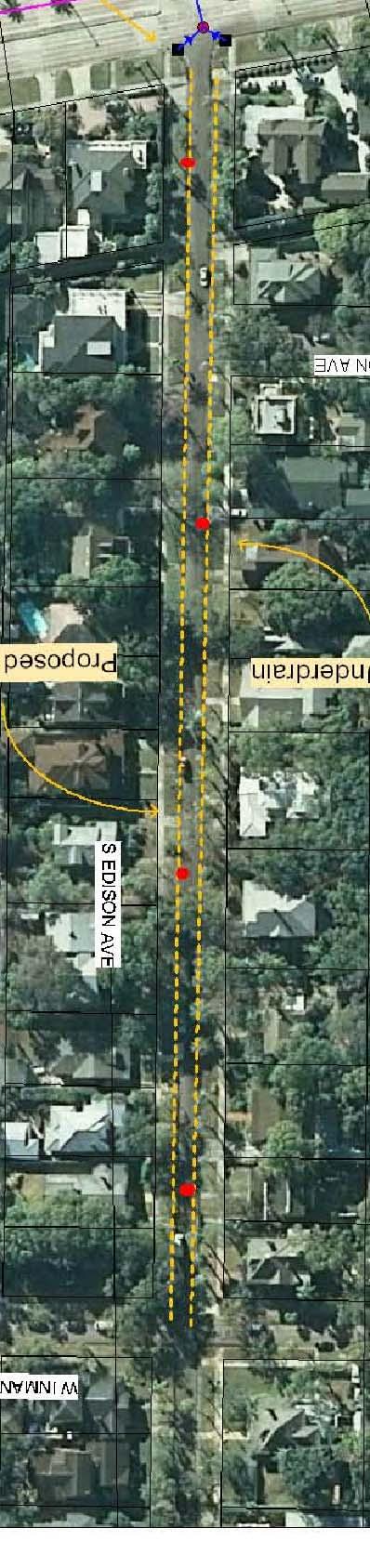
4 S. Edison Avenue Roadway Improvements Phase 1 City of Tampa, Florida MC 2 Project No. T GEOTECHNICAL ENGINEERING SERVICES REPORT Authorization INTRODUCTION This report presents the findings of our shallow subsurface investigation and pavement cores evaluation for the City of Tampa in Hillsborough County, Florida. The services for this project were performed in general accordance with our Proposal T dated April 4, Authorization to perform our services was in the form of acceptance of our proposal by Ms. Barbara Graves, City of Tampa DPW Stormwater Engineering. PROJECT INFORMATION Project information has been provided by Ms. Barbara Graves and Mr. Michael Miller of the City of Tampa Stormwater Division through communications including an aerial photo showing the roadways where underdrain is proposed, a copy of a Hyde Park Seepage Evaluation dated April 22, 2013 prepared by Michael Miller, and a copy of a Review of the Hyde Park Seepage Evaluation dated December 30, 2013 by Arehna Engineering, Inc. The aerial provided indicated proposed underdrains along S. Delaware Ave., S. Edison Ave. and S. Boulevard from W. Inman Ave to Bayshore Blvd., a distance of approximately 1,100 feet for each segment. Based on our understanding, the project will be constructed in three phases. Phase 1 will extend along S. Edison Avenue, Phase 2 along S. Delaware Street and Phase 3 along S. Boulevard. The request for proposal provided to us requested four (4) Standard Penetration Test (SPT) borings to a depth of 10 feet along S. Edison Ave. (Phase 1) and coring of the existing pavement at 4 locations with associated soils and pavement analysis to evaluate the base needed for roadway reconstruction. It was the intent of this investigation to perform subsurface investigations to determine the composition of the sub-base materials along the project limits (for Phase 1 only) including the composition of the existing shallow subsurface soils as well as the existing pavement asphalt, base and subbase thickness. We understand that the actual new pavement will be designed by the City of Tampa staff. Coring of the existing pavement to determine existing depth of asphalt and base material was also performed for Phase 1 of this project described herein. Scope of Services The purpose of these services was to assess the existing roadway and shallow subsurface conditions along S. Edison Avenue extending south from W. Inman Avenue 1
5 S. Edison Avenue Roadway Improvements Phase 1 City of Tampa, Florida MC 2 Project No. T to Bayshore Blvd. (Phase 1 only) as further defined in this report. Our scope specifically excludes recommendations of the type and size of underdrains and our assumptions are that properly designed underdrains will enable a minimum seperation between the estimated seasonal high ground water and the bottom of the base of the pavement of 18 inches or 12 inches as recommended below. Specifically, the scope of the exploration and analysis included the following: 1. Conducted a visual reconnaissance of the project site. Review the USDA Soil Survey for Hillsborough County and the USGS topographic maps. We will also review any existing plans provided to us along the project limits. Tentative boring locations have been identified on the aerial provided to us. 2. Performed a total of four (4) Standard Penetration Test (SPT) borings thru the existing pavement in locations provided to us and subject to adjustment based on utilities present. The SPT borings will be performed to a depth of approximately ten (10) feet below ground surface for Phase 1 of this project. 3. Performed a total of four (4) pavement cores along S. Edison Ave. to determine the thickness of the existing asphalt, base and subbase materials along the project limits for Phase 1 of this project. 4. Visually examined all recovered pavement and soil samples in the laboratory. Performed limited laboratory testing as required to help classify soils including percent passing the 200 sieve, natural moisture and organic content testing. The data was summarized in a geotechnical data report to be used by the City of Tampa in developing pavement and underdrain recommendations for the project. Our report included the following: 1. Summary of the subsurface conditions encountered along the roadway limits for Phase 1 (along S. Edison Ave. from W. Inman Ave. to Bayshore Boulevard) was provided in this summary report. We also provided information regarding encountered water table and recommendations for subgrade materials including suggested depth of excavation to assist the designers with roadway reconstruction design and need for underdrains; however, final pavement and underdrain design is not a part of our scope of services. SUBSURFACE EXPLORATION To explore the general subsurface conditions, four (4) SPT borings were performed to a depth of 10 feet below the exiting ground surface along S. Edison Avenue. In addition, the four (4) pavement cores were performed at the same location. The boring and 2
6 S. Edison Avenue Roadway Improvements Phase 1 City of Tampa, Florida MC 2 Project No. T pavement locations where provided by the City of Tampa DPW Stormwater Engineering department. The SPT borings were completed in accordance with ASTM D-1586 using a trailer mounted drill rig. Soil samples were collected and N-value resistances were measured virtually continuously in the top 10 feet and then on 5-foot intervals thereafter. The soils encountered in the borings were sampled and stored in sealed containers, then returned to our laboratory for visual classification. The SPT resistance ('N') values reported at various depth intervals on the boring logs represent the number of hammer blows (140 pound hammer falling 30 inches) required to advance a 1-3/8 inch split spoon sampler a distance of one foot. The SPT soil profiles and pavement core are included in the Boring Location/Report of Core Borings, Sheet 1 in the Appendix of this report. Boring Location In general, the site is along at S. Edison Avenue (Phase 1) in Hillsborough County, Florida. The new locations of the proposed four (4) borings were selected by the City of Tampa. The site plan indicating the approximate boring locations is presented in Sheet 1 in the Appendix of this report. The location of the SPT borings were adjusted slightly in the field due to access issues and to avoid below ground surface utilities. General LABORATORY TESTING The soil samples were transported to our laboratory and were visually classified by a Geotechnical Engineer in general accordance with the American Society of Testing and Materials (ASTM) test designation D-2488, titled "Description and Identification of Soils (Visual-Manual Procedure)". The Unified Soil Classification was used for soil classification. The initial classification was based on visual observations and a laboratory testing program done to confirm the initial classification. A laboratory testing program was performed on selected representative samples. The laboratory testing was conducted in general conformance to ASTM standards and FDOT practices. Some procedural variations not considered material to the test data or to the conclusions reached herein may have been taken. The laboratory tests included moisture content tests, percent passing the No. 200 sieve and organic content tests. A summary of the laboratory results is included in Table 2 in the Appendix. Moisture Content The laboratory moisture content test consists of the determination of the percentage of moisture contents in selected samples in general accordance with FDOT test designation FM 1-T265 (ASTM test designation D-2216). Briefly, natural moisture 3
7 S. Edison Avenue Roadway Improvements Phase 1 City of Tampa, Florida MC 2 Project No. T content is determined by weighing a sample of the selected material and then drying it in a warm oven. Care is taken to use a gentle heat so as not to destroy any organics. The sample is removed from the oven and reweighed. The difference of the two weights is the amount of moisture removed from the sample. The weight of the moisture divided by the weight of the dry soil sample is the percentage by weight of the moisture in the sample. Percent passing the -200 Sieve The wash gradation test measures the percentage of a dry soil sample passing the No. 200 sieve. By definition in the Unified Soil Classification System, the percentage by weight passing the No. 200 sieve is the silt and clay content. The amount of silt and clay in a soil influences it properties, including permeability, workability and suitability as fill. This test was performed in general accordance with ASTM D-1140 (Standard Test Methods for Amount of Material Finer Than the No. 200 (75 μm) Sieve). Organic Content The laboratory organic content test consists of drying the soil sample, then heating it in a small furnace to a minimum temperature of 400 degrees Centigrade for 6 hours. The high heat burns off all organic material, leaving only the soil minerals. The difference in the weight prior to and after the burning is the weight of the organics. The weight of the organics divided by the weight of the dried soil is the percentage of the organics within a sample. The organic content testing procedure were conducted in general accordance with the FDOT test designation 1-T267 (ASTM 2974 (Standard Test Methods for Moisture, Ash, and Organic Matter of Peat and Other Organic Soils)). GENERAL SITE AND SUBSURFACE CONDITIONS Soil Survey of Hillsborough County. The U.S. Department of Agriculture - Soil Conservation Service now known as the Natural Resources Conservation Service (NRCS), has mapped the shallow soils in this area of Hillsborough County. This information was outlined in a report titled The Soil Survey of Hillsborough County Florida using Version 11 dated December 17, The aerial images were photographed between Feb 10, 2010 and March 13, The Soil Survey describes the soils at the different intersections as described in Table 1 in the Appendix (mapping unit No. 55 Tavares-Urban land complex, 0 to 5% slopes. Small areas of other soil types may be present within the mapping unit. Urban land is covered with buildings and pavements and contains soils altered by development so that their identification is not feasible. 4
8 S. Edison Avenue Roadway Improvements Phase 1 City of Tampa, Florida MC 2 Project No. T The water table can be expected to vary at times and will fluctuate seasonally based on rainfall quantities, area geology, surface drainage conditions and other factors. The area of our study has experienced chronic flooding during intense storm events based upon personal observations in the past. A summary of the groundwater levels encountered at the time of our drilling and seasonal high groundwater level is presented in Table 1 in the Appendix. If groundwater levels are critical for design, the installation of temporary piezometers (wells) throughout the sites is recommended to obtain groundwater level data over dry and wet periods. The USDA Soil Survey is not necessarily an exact representation of the soils on the site. The mapping is based on interpretation of aerial maps with scattered shallow borings for confirmation. Accordingly, borders between mapping units are approximate and the change may be transitional. Differences may also occur from the typical stratigraphy, and small areas of other similar and dissimilar soils may occur within the soil-mapping unit. As such, there may be differences between the mapped description and the borings descriptions obtained for this report. The survey is, however, a good basis for evaluating the shallow soil conditions of the area. Subsurface Conditions The following subsurface description is of a generalized nature, provided to highlight the major soil strata encountered. The SPT boring logs included in our report should be reviewed for specific information as to individual test locations. The stratifications shown on the boring logs represent the conditions only at the actual test locations. Variations may occur and should be expected between test locations. The stratifications represent the approximate boundary between subsurface materials and the transition may be gradual. A total of four SPT borings and four pavement cores and were performed for Phase 1 along S Edison Avenue to depths of 10 feet. The locations and results of the borings performed are shown on the Boring Location Plan/Report of Core Borings, Sheet 1 included in the Appendix of our report. In general, the subsurface conditions encountered below the asphalt pavement consisted of approximately 0.64 (7.75 inches) to 1.1 feet (13.50 inches) of shell base followed by very loose to medium fine sands (SP/SP-SM/SP-SC) with occasional traces of shell extending to the boring termination depth of 10 feet. Isolated thin layers of soft organic sandy silt (OL) and slightly organic silty sand (SM) were encountered in borings B-1 and B-3 extending from depths ranging from 2.0 to 4.0 and 3.5 to 4.0, respectively. Based on the limited information at this time, the horizontal and vertical extent of the soft (with very low permeability) organic sandy silt found is not known in boring B-1 and further delineation will be required. 5
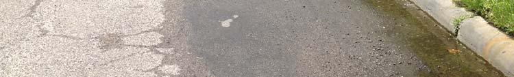
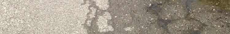
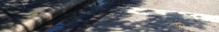
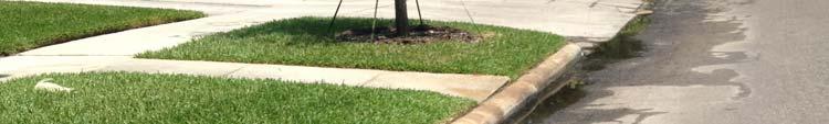
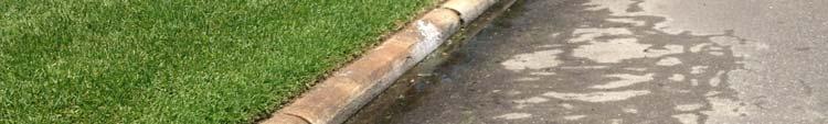
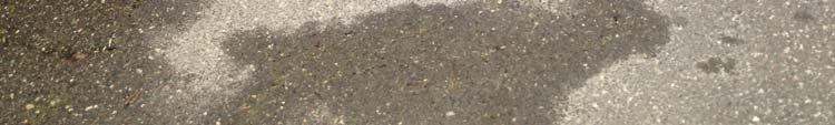
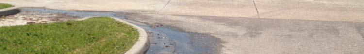
9 S. Edison Avenue Roadway Improvements Phase 1 City of Tampa, Florida MC 2 Project No. T Groundwater Information During the performance of our subsurface investigation, groundwater was at depths of 1.5 feet below the existing ground surface in the SPT borings performed on April 22, The water table can be expected to vary at times and will fluctuate seasonally based on rainfall quantities, area geology, surface drainage conditions and other factors. Based on our review of the Soil Survey of Hillsborough County, Florida and soil samples collected in the field, we estimate the Seasonal High Water to be as shown in Table 1 in the Appendix. The area of our study has experienced chronic flooding during intense storm events based upon personal observations in the past. Pavement Coring Information A total of four (4) pavement cores were performed at the approximate locations shown in Sheet 1 in the Appendix to determine the existing pavement structure. The following summarizes the results of the pavement cores performed. Boring/Pavement Core No. (see Sheet 1 for approximate locations) Asphalt Friction and Structural Course thickness, inches Shell Base thickness, inches Total Depth/thickness, inches B-1/PC B-2/PC B-3/PC Fill (Fine sand with shell) B-4/PC Notes: Average Range The estimated thickness above were measured at four locations along the perimeter and averaged. The results of the shell base thickness of PC-3 were not considered for calculating the average and range results. Site Visit on May 8, 2014 Standing water was observed in many places along S. Edison Avenue and S. Boulevard and S. Delaware Avenue (see photos in the Appendix) on this date. Last heavy rain occurred on May 2, The conditions observed in the field are more critical than the isolated (low permeability) organic sandy silt (OL) found in boring B-1 and more shallow impermeable soils exist in this area. In addition, this condition has also caused cracking distress in the pavement. It may be necessary to reconstruct both the asphalt surface and underlying shell base in some areas and during severe weather events the underdrain system may not be 6
10 S. Edison Avenue Roadway Improvements Phase 1 City of Tampa, Florida MC 2 Project No. T sufficient to maintain the groundwater below the base. EVALUATION AND RECOMMENDATIONS (PHASE 1) The subsurface conditions encountered below the asphalt pavement consisted of approximately 0.64 (7.75 inches) to 1.1 feet (13.50 inches) of shell base followed by very loose to medium fine sands (SP/SP-SM/SP-SC) with occasional traces of shell extending to the boring termination depth of 10 feet. Isolated thin layers of soft organic sandy silt (OL) and slightly organic silty sand (SM) were encountered in borings B-1 and B-3 extending from depths ranging from 2.0 to 4.0 and 3.5 to 4.0, respectively. Based on the limited information at this time, the horizontal and vertical extent of the soft (with very low permeability) organic sandy silt found is not known in boring B-1 and delineation the extent of it will be required. In general, the existing shallow subsurface soils encountered in the borings performed are capable of supporting the proposed construction of a typical pavement section after subgrade preparation in accordance with FDOT Standards., with the exception of the organic sandy silt (OL) encountered in boring B-1. During construction, any buried organic soils, debris and/or unsuitable soils encountered should be removed and replaced with suitable compacted sandy soils. Similarly, plastic and organic soils (OL), such as the ones encountered in boring B-1 should be removed in accordance with FDOT Index 500 and placed in areas not affecting pavement performance. The removal of topsoils and after superficial organic soils within the top 1 foot should be in accordance with FDOT Standard Specifications for Road and Bridge Construction, Section 110. Organic soils are highly compressible and may cause excessive settlement if left in place. This material is also susceptible to significant secondary compression settlements. Pavement Recommendations The existing shell base does not appear to be in good condition in areas (infiltrated water) and eroded should be removed and/or replaced. Some of the existing shell base might be salvaged, provided it is re-installed and compacted properly. In general, following the completion of the clearing and grading operations and overexcavation of the organic and clayey compacted fill or natural shallow sandy soils should be acceptable for construction and support of a flexible (limerock, crushed concrete, or shell base) or semi-flexible (soil cement base) type pavement section. Any fill utilized to elevate the cleared pavement areas to subgrade elevation should consist of reasonably clean (maximum 12% passing #200 sieve sizes) fine sands uniformly compacted to a minimum density of 98% of the modified Proctor maximum dry density. 7
11 S. Edison Avenue Roadway Improvements Phase 1 City of Tampa, Florida MC 2 Project No. T The choice of pavement base type will depend on final pavement grades. If a minimum separation of 18 inches between the bottom of the base and the seasonal high groundwater level is obtained, then a limerock, shell, or crushed concrete base can be utilized. A soil cement base should be utilized if the separation between final grade and the seasonal high groundwater is a minimum of 12 inches. Limerock and shell base material should meet Florida Department of Transportation (FDOT) requirements including compaction to a minimum density of 98% of the modified Proctor maximum dry density and a minimum Limerock Bearing Ratio (LBR) of 100. Crushed concrete should have an LBR value of 100 and be graded in accordance with FDOT Standard Specification Section 204. Due to the expected subgrade soil conditions, we recommend type B or C stabilized subgrade (LBR = 40) as specified by the FDOT Standard Specifications for Road and Bridge Construction. A soil cement base should be designed according to FDOT or PCA modified short cut design procedures. A strength of 300 psi should be achieved on laboratory cured compressive strength specimens molded from samples taken from the base material as it is placed. A stabilized subgrade need not be incorporated with soil cement base. As another option, an asphaltic concrete base may be utilized if the separation between final grade and the seasonal high groundwater is a minimum of 6 inches. The asphalt material base should meet Florida Department of Transportation (FDOT) requirements including compaction to a minimum density of 96% of the Marshall maximum laboratory unit weight. Actual pavement section thickness will be provided by the design civil engineer from the City of Tampa based on traffic loads, volume, and the owners design life requirements. The above sections represent minimum thicknesses representative of typical load and construction practices and as such periodic maintenance should be anticipated. All pavement materials and construction procedures should conform to the FDOT or appropriate city or county requirements. REPORT LIMITATIONS The findings detailed herein are based on the available soil and pavement information obtained by MC 2 and also the information provided by Ms. Barbara Graves, City of Tampa DPW Stormwater Engineering for the proposed project. If there are any revisions to the plans for this project or if deviations from the subsurface conditions noted in this report are encountered during construction, MC 2 should be notified immediately to determine if changes or other recommendations are required. In the event that MC 2 is not retained to perform these functions, MC 2 can not be responsible for the impact of those conditions on the performance of the project. The geotechnical engineer warrants that the findings, recommendations, specifications, or professional advice contained herein have been made in accordance with generally 8
12 S. Edison Avenue Roadway Improvements Phase 1 City of Tampa, Florida MC 2 Project No. T accepted professional geotechnical engineering practices in the local area. No other warranties are implied or expressed. After the plans and specifications are more complete, the geotechnical engineer should be provided the opportunity to review the final design plans and specifications to assess that our engineering findings have been properly incorporated into the design documents. At that time, it may be necessary to submit supplementary recommendations. This report has been prepared for the exclusive use of the City of Tampa, Florida. 9
13 APPENDIX Summary of Boring Information and Estimated Seasonal High Groundwater Table - Table 1 Summary of Laboratory Test Results Table 2 Boring Location Plan/Report of Core Borings Sheet 1 Site Photographs Test Procedures
14 Boring No. B-1 B-2 B-3 B-4 Boring Location 134 North of C/L of Bayshore Blvd. and 6 West from EOC 150 North of Morrison Ave. and 6 West from EOC 450 North of Morrison Ave. and 5 West from EOC 70 South of Inman Ave. and 6 East from EOC Table No. 1 Summary of Boring Information and Estimated Seasonal High Groundwater Table S. Edison Avenue Roadway Improvements Phase 1 City of Tampa, Florida MC 2 Inc. Project No. T USDA Soil Type USDA Seasonal High Groundwater Table Depth (ft) Measured Groundwater Depth (April 2014) (ft) S. Edison Avenue from Bayshore Blvd. to W. Inman Avenue (Phase 1) (mapping unit No. 55) Tavares-Urban land complex, 0 to 5% slopes is covered with buildings and pavements and contains soils altered by development so that their identification is not feasible. Moderately well drained. 3.5 to Estimated Seasonal High Groundwater Levels Depth (ft) +0.0 (perched above the organic sandy silty (OL) layer Other USDA Sols within the nearby project limits area (W. Inman Ave., S. Delaware Ave., Bayshore Blvd. and S. Boulevard) NE corner of S. Boulevard - (mapping unit No. 22) Immokalee- Urban land complex is covered with buildings and pavements and contains
15 Table No. 1 Summary of Boring Information and Estimated Seasonal High Groundwater Table S. Edison Avenue Roadway Improvements Phase 1 City of Tampa, Florida MC 2 Inc. Project No. T Boring No. W. Inman Ave. Approx. 200 to 600 ft. North of corner of S. Boulevard and Bayshore Blvd. 200 North of corner of S. Boulevard and Bayshore Blvd. along S. Boulevard, S. Edison Ave and S. Delaware Ave. Boring Location - -- USDA Soil Type soils altered by development so that their identification is not feasible. Poorly drained. (mapping unit No. 32) Myakka-Urban land complex is covered with buildings and pavements and contains soils altered by development so that their identification is not feasible. Poorly drained. (mapping unit no. 27) Malabar fine sand. Poorly drained. USDA Seasonal High Groundwater Table Depth (ft) to 1.0 Measured Groundwater Depth (April 2014) (ft) Estimated Seasonal High Groundwater Levels Depth (ft)
16 Table No. 1 Summary of Boring Information and Estimated Seasonal High Groundwater Table S. Edison Avenue Roadway Improvements Phase 1 City of Tampa, Florida MC 2 Inc. Project No. T Boring No. Boring Location Notes: 1. EOC= Edge of curb USDA Soil Type USDA Seasonal High Groundwater Table Depth (ft) Measured Groundwater Depth (April 2014) (ft) Estimated Seasonal High Groundwater Levels Depth (ft)
17 Table 2 Summary of Laboratory Test Results S. Edison Avenue Roadway Improvements Phase 1 City of Tampa, Florida MC 2 Inc. Project No. T Boring No. Depth (ft) USCS Classi. Sieve Analysis (% Passing) #10 #20 #40 #60 #100 #140 #200 Liquid Limit (%) Plastic Index (%) Organic Content (%) Natural Moisture Content (%) B OL organic sandy silt S. Edison Avenue from Bayshore Blvd. to W. Inman Avenue (Phase 1) B SP 4 25 B SP B SM (slightly organic silty sand)
18
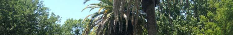


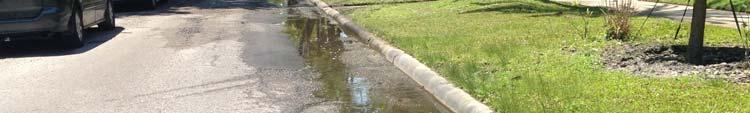
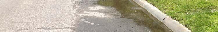
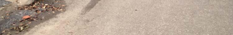
19 SITE PHOTOGRAPHS Photo 1: S. Edison Ave


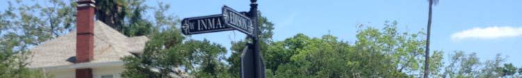


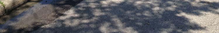
20 Photo 2: W. Inman Ave and S. Edison Ave


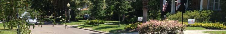
21 Photo 3: S. Boulevard Ave


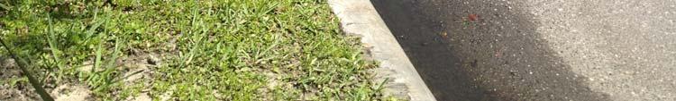
22 Photo 4: S. Boulevard Ave and W. Inman Ave


23 Photo 5: S. Delaware Ave.


24 Photo 6: S. Delaware Ave and Bayshore Blvd
25 TEST PROCEDURES The general field procedures employed by MC Squared, Inc. (MC 2 ) are summarized in the American Society for Testing and Materials (ASTM) Standard D420 which is entitled "Investigating and Sampling Soil and Rock". This recommended practice lists recognized methods for determining soil and rock distribution and groundwater conditions. These methods include geophysical and in-situ methods as well as borings. Standard Drilling Techniques To obtain subsurface samples, borings are drilled using one of several alternate techniques depending upon the subsurface conditions. Some of these techniques are: In Soils: a) Continuous hollow stem augers. b) Rotary borings using roller cone bits or drag bits, and water or drilling mud to flush the hole. c) "Hand" augers. In Rock: a) Core drilling with diamond-faced, double or triple tube core barrels. b) Core boring with roller cone bits. The drilling method used during this exploration is presented in the following paragraph. Hollow Stem Augering: A hollow stem augers consists of a hollow steel tube with a continuous exterior spiral flange termed a flight. The auger is turned into the ground, returning the cuttings along the flights. The hollow center permits a variety of sampling and testing tools to be used without removing the auger. Core Drilling: Soil drilling methods are not normally capable of penetrating through hard cemented soil, weathered rock, coarse gravel or boulders, thin rock seams, or the upper surface of sound, continuous rock. Material which cannot be penetrated by auger or rotary soil-drilling methods at a reasonable rate is designated as refusal material. Core drilling procedures are required to penetrate and sample refusal materials. Prior to coring, casing may be set in the drilled hole through the overburden soils, to keep the hole from caving and to prevent excessive water loss. The refusal materials are then cored according to ASTM D-2113 using a diamond-studded bit fastened to the end of a hollow, double or triple tube core barrel. This device is rotated at high speeds, and the cuttings are brought to the surface by circulating water. Core samples of the material penetrated are protected and retained in the swivel-mounted inner tube. Upon completion of each drill run, the core barrel is brought to the surface, the core recovery is measured, and the core is placed, in sequence, in boxes for storage and transported to our laboratory. Sampling and Testing in Boreholes Several techniques are used to obtain samples and data in soils in the field; however the most common methods in this area are: a) Standard Penetration Testing b) Undisturbed Sampling c) Dynamic Cone Penetrometer Testing
26 d) Water Level Readings The procedures utilized for this project are presented below. Standard Penetration Testing: At regular intervals, the drilling tools are removed and soil samples obtained with a standard 2 inch diameter split tube sampler connected to an A or N-size rod. The sampler is first seated 6 inches to penetrate any loose cuttings, and then driven an additional 12 inches with blows of a 140 pound safety hammer falling 30 inches. Generally, the number of hammer blows required to drive the sampler the final 12 inches is designated the "penetration resistance" or "N" value, in blows per foot (bpf). The split barrel sampler is designed to retain the soil penetrated, so that it may be returned to the surface for observation. Representative portions of the soil samples obtained from each split barrel sample are placed in jars, sealed and transported to our laboratory. The standard penetration test, when properly evaluated, provides an indication of the soil strength and compressibility. The tests are conducted according to ASTM Standard D1586. The depths and N- values of standard penetration tests are shown on the Boring Logs. Split barrel samples are suitable for visual observation and classification tests but are not sufficiently intact for quantitative laboratory testing. Water Level Readings: Water level readings are normally taken in the borings and are recorded on the Boring Records. In sandy soils, these readings indicate the approximate location of the hydrostatic water level at the time of our field exploration. In clayey soils, the rate of water seepage into the borings is low and it is generally not possible to establish the location of the hydrostatic water level through short-term water level readings. Also, fluctuation in the water level should be expected with variations in precipitation, surface run-off, evaporation, and other factors. For long-term monitoring of water levels, it is necessary to install piezometers. The water levels reported on the Boring Logs are determined by field crews immediately after the drilling tools are removed, and several hours after the borings are completed, if possible. The time lag is intended to permit stabilization of the groundwater level that may have been disrupted by the drilling operation. Occasionally the borings will cave-in, preventing water level readings from being obtained or trapping drilling water above the cave-in zone. BORING LOGS The subsurface conditions encountered during drilling are reported on a field boring log prepared by the Driller. The log contains information concerning the boring method, samples attempted and recovered, indications of the presence of coarse gravel, cobbles, etc., and observations of groundwater. It also contains the driller's interpretation of the soil conditions between samples. Therefore, these boring records contain both factual and interpretive information. The field boring records are kept on file in our office. After the drilling is completed a geotechnical professional classifies the soil samples and prepares the final Boring Logs, which are the basis for our evaluations and recommendations.
27 SOIL CLASSIFICATION Soil classifications provide a general guide to the engineering properties of various soil types and enable the engineer to apply his past experience to current problems. In our investigations, samples obtained during drilling operations are examined in our laboratory and visually classified by an engineer. The soils are classified according to consistency (based on number of blows from standard penetration tests), color and texture. These classification descriptions are included on our Boring Logs. The classification system discussed above is primarily qualitative and for detailed soil classification two laboratory tests are necessary; grain size tests and plasticity tests. Using these test results the soil can be classified according to the AASHTO or Unified Classification Systems (ASTM D-2487). Each of these classification systems and the in-place physical soil properties provides an index for estimating the soil's behavior. The soil classification and physical properties are presented in this report. The following table presents criteria that are typically utilized in the classification and description of soil and rock samples for preparation of the Boring Logs.
28 Relative Density of Cohesionless Soils From Standard Penetration Test Very Loose Loose Medium Dense Dense Very Dense Very Soft Soft (bpf = blows per foot, ASTM D 1586) Relative Hardness of Rock < 4 bpf 5-10 bpf bpf bpf > 50 bpf Hard Rock disintegrates or easily compresses to touch; can be hard to very hard soil. May be broken with fingers. Moderately Soft May be scratched with a nail, corners and edges may be broken with fingers. Moderately Hard Light blow of hammer required to break samples. Very Soft Soft Firm Stiff Very Stiff Hard Very Hard Consistency of Cohesive Soils Particle Size Identification < 2 bpf 3-4 bpf 5-8 bpf 9-15 bpf bpf bpf > 50 bpf Boulders Larger than 12" Cobbles 3" - 12" Gravel Coarse 3/4" - 3" Fine 4.76mm - 3/4" Sand Coarse Medium Fine mm mm mm Hard Hard blow of hammer required to break sample. Fines (Silt or Clay) Smaller than mm Rock Continuity Relative Quality of Rocks RECOVERY = Total Length of Core x 100 % Length of Core Run Description Core Recovery % Incompetent Less than 40 Competent Fairly Continuous Continuous RQD = Total core, counting only pieces > 4" long x 100 % Length of Core Run Description RQD % Very Poor 0-25 % Poor % Fair % Good % Excellent %