Overview of Machinery Condition Monitoring and Diagnostics with Case Study. Roengchai Chumai Technical Leader, GE Oil & Gas
|
|
|
- Warren Reynolds
- 5 years ago
- Views:
Transcription


1 Overview of Machinery Condition Monitoring and Diagnostics with Case Study Roengchai Chumai Technical Leader, GE Oil & Gas
2 Agenda Introduction Machinery Protection System Machinery Management System Common Machine Malfunctions Case Study Q & A
3 MACHINERY CONDITION MONITORING CONCEPT


4 Introduction The first machine monitoring systems employed were human senses. Over time and through experience, a person would gain skill to sense when a failure was occurring. Unfortunately, this experience was often gained through observation of an actual machine failure.


5 Machinery Protection System Systems that shutdown a machine or return it to a safe or nondestructive mode of operation without human intervention.


6 Machinery Protection System Online - continuous monitoring & protection Vibration Monitor Vibration Card Portable Data Collector Machine Control System Critical Assets Gas Turbines Compressors Main line Pumps Recip Compressors Basic Trends and Status only
7 Machinery Management System Use of systems that provide data and information that is interpreted and applied by people to correctly operate, maintain, and assess the condition of their machinery. Machinery Management requires information!
 monitoring Switch/Hub SCANNING Monitor ONLINE Monitor OFFLINE Portable Data Collector")
 + thermography, third party devices & lube")
8 Machinery Management System Online - continuous monitoring & protection Online periodic (scanning) monitoring Switch/Hub SCANNING Monitor ONLINE Monitor OFFLINE Portable Data Collector Critical Assets Gas Turbines Steam Turbines Generators BFW Pumps Essential Assets Fans Pumps Blowers Etc BOP Assets Offline portable (walk-around) + thermography, third party devices & lube oil analysis
9 Machine Data Direct measurement Vibration and Position Rotor Speed Bearing Temperature Indirect Measurement Process data e.g. pressure, flow, molecular weight, MW, MVAR, etc. Performance data
10 Vibration Measurements Overall Vibration Amplitude Position Frequency nx Filtered Vibration Amplitude & Phase Shape or Form You must have access to this information to properly manage your machine.
11 Machine Operating Modes A. Steady State : Constant Machine Speed Process or Load Change B. Transient : Start Up Shut Down C. Slow Roll D. Stopped
12 COMMON MACHINE MALFUNCTIONS
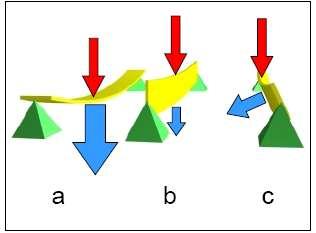
13 Machine Malfunction Identification Vibration Response Forces DynamicStiffness When vibration is viewed as a ratio of forces to stiffness, the perspective changes and the focus becomes What has changed in the machine, the forces acting on it or its stiffness? rather than simply more vibration is bad, less vibration is good. Natural Frequency Stiffness Mass
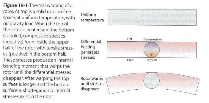
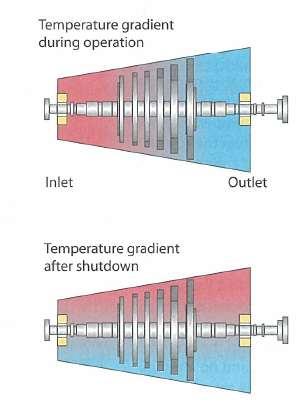
14 Shaft Bow
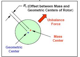
15 Unbalance
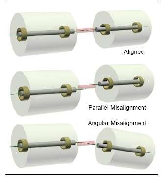
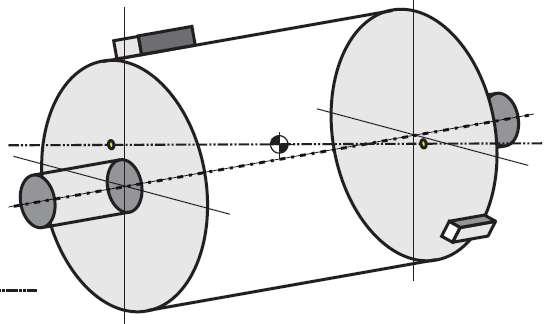
16 Misalignment

17 5. Improper alignment Misalignment Causes of Misalignment 1. Thermal growth 2. Foundation problems - include cracked grouting, a loose soleplate, and loose anchor bolts 3. Soft Foot the case is wrap because one or more machine feet are not coplanar after tightening hold down bolts cause from inadequate shimming or by an excessive number of shims 4. Piping strain


18 Misalignment Effects 1. Rub - cause the rotor to wipe bearings and seals 2. Shortened Bearing Life - by rub and temperature 3. Damaged Seals/Packing - deflect shafts and push seals and packing outside design limits 4. Cracked Shafts - deflect beyond the design limits can create high reversal stresses 5. Shortened Coupling Life - by producing extreme heat in elastomer couplings


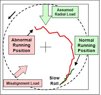
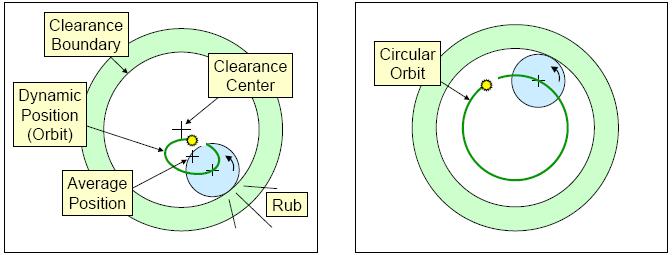
19 Rubbing Causes of Rub 1. Radial Load 2. High Vibration 3. Axial Thrust 4. Locked Seals
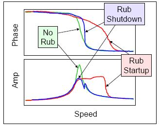
20 Rubbing
21 Rubbing

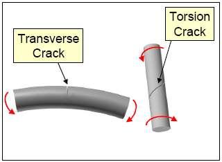
22 Shaft Crack Shaft cracks begin in regions of high local stress. Shafts are subjected to large-scale stresses due to static or dynamic bending and torsional twisting, static radial loads, or residual stresses from heat treatment, welding, or machining operations.

23 Shaft Crack

24 Shaft Crack

25 Shaft Crack


26 Fluid Induced Instability When a rotor operates in fluid-induced instability, it is actually operating in a stable limit cycle of high vibration. But the rotor is unstable in the sense that it is operating outside desired operational limits.

27 Fluid Induced Instability
28 Many Other Malfunctions Surging & Rotating Stall in Compressor Pump Cavitation Super synchronous instability in Pump Combustion Rumble in Gas Turbine Thermal Sensitivity in Generator Crack/Broken Rotor Bar in Motor Rough Load Zone in Hydraulic Turbine Synchronous Instability (Morton Effect) Torsional-Lateral Coupled Vibration Structure/Resonance Induced Vibration etc.
29 MACHINERY DIAGNOSTICS CASE STUDY
30 Case Study#1-Steam Turbine-Generator Set The unit was run at normal operating condition. Fluctuating vibration amplitudes observed at Brg#3 & #4 of IP turbine Contacted machinery diagnostic services engineer to site for vibration analysis
31 Machine Information Steam turbine-generator set, 762 MW in coal fired power plant Well instrumented with X-Y probes each bearing plus a Keyphasor Problem noted at Brg#3 & #4 of IP Turbine

32 Direct & 1X Trend Plots Brg# microns, pp microns, pp microns, pp microns, pp

33 Trend Plots Brg#3 & #4
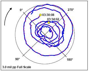
34 Polar Plots Brg#3
35 Polar Plots of Brg#3 & #4 s

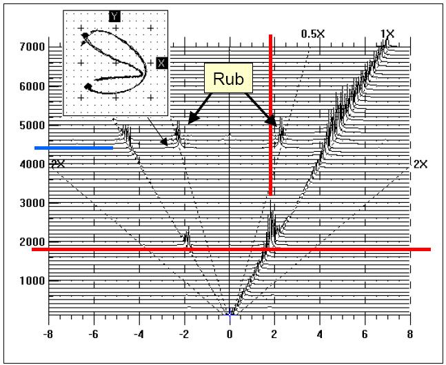
36 Waterfall Plot of Brg#3 s Vibration 1X Vibration
37 Waterfall Plot of Brg#4 s Vibration 1X Vibration

38 Plus Orbit Shapes vs. Trend Obstructed Rotor Movement shown in Orbit Shape
39 Conclusions & Recommendations High vibration amplitude at brg#3 was due to increasing 1X vibration Synchronous (1X) vibration changed in amplitude and phase at brg#3 & #4 Obstructed orbit shape was observed at brg#3 It was suspected rubbing around brg#3 (e.g. oil deflection) and recommended to inspect at the next opportunity available.


40 Inspection Results Coke Deposits Rubbing Marks

41 Case Study#2 Hydro turbine-generator Set Francis runner type hydro turbine & reversible pump Rated output at 145 MW at turbine mode XY probes installed at all three guide bearings Online machine condition monitoring system installed It is reported excessive vibration at turbine guide bearing when reducing load before shutdown

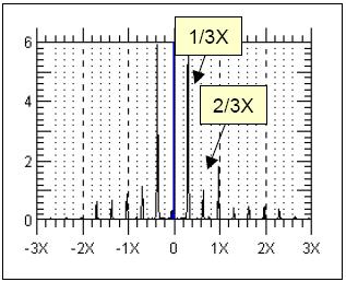
42 Turbine Speed & Vibration Trend vs. Spectrum Turbine Speed 0.35X 1X Phase Overall Amplitude 1X Amplitude Overall vibration amplitude of turbine increased due to 0.35X component.

43 Unstable Orbit Shape w/ Predominant 0.35X um, hrs. Turbine bearing clearance is 500 um um, hrs. Be aware of bearing worn out!
44 Spectrum of Unstable Vibration 232 um, 102 um,
45 Conclusions & Recommendations Unstable vibration occurred in short period when reducing load before shutdown Predominantly at subsynchronous vibration at 0.25X to 0.35X with unstable orbit shape Above characteristics are recognized as Rough Load Zone or Spiral Vortex in draft tube Recommendations Avoid operation at 25% to 70% wicket gate opened Apply air injection at draft tube, if above load range cannot be avoided

46 Vortex Interaction Rough Load Zone Zone of flow separation and vortex formation Spiral vortex filaments

47 Comment! Or Question?