Performance Analysis on CHP Plant Using Back Pressure Turbine According to Return Temperature Variation
|
|
|
- Adela Hunt
- 5 years ago
- Views:
Transcription


1 Performance Analysis on CHP Plant Using Back Pressure Turbine According to Return Temperature Variation IDEA 2016(107 th Annual Conference & Trade show) Embracing Change Jong Jun Lee, Shin Young Im Korea District Heating Corporation
2 Contents Introduction System Modeling Results Conclusion
3 Introduction System Modeling Results Conclusion

4 Introduction Research Background Definition of CHP(Combined Heat & Power) One of the Power generation system which can generate electricity and heat Source : IDEA 2016(107 th Annual Conference) Embracing Change


5 Introduction Research Background Combined Heat & Power(CHP) System is one of the solution for using energy more efficiently High efficiency and low emissions comparing to conventional Electricity and heat generation Catalog of CHP Technologies, U.S. Environmental protection Agency CHP Partnership, 2008 A decade of progress Combined Heat and Power, U.S. Department of Energy,
 pressure")

 High initial investment Complex control system")
6 Introduction Combined Heat & Power Condensing Turbine & Back pressure turbine Back pressure type Single(Double) pressure system Narrow range Control Heat & Power ratio More easy control system than Condenser type Condensing type Multi pressure system Wide range Control Heat & Power ratio(mode Operation) High initial investment Complex control system Condenser required 6
 (Elec.")


7 Introduction Combined Heat & Power Mode Operations (Heat Demand mode) (Elec. Demand mode) Consumer (Complex demand mode) Consumer Benefits of Mode Operations Wide range control of Heat- Electricity ratio Possible to respond for seasoning heat/electricity demands Possible to maximize revenue Securing Reliability of Heat & Power generation 7
 cooling water temperature variations Condensing pressure varied by cooling water temperature difference Heat drop of")

8 Introduction Steam Rankine Cycle Performance of SRC(Steam Rankine Cycle) may changing depends on the Condenser(District Heater) cooling water temperature variations Condensing pressure varied by cooling water temperature difference Heat drop of turbine inlet and exit are changed when the condensing pressure varied In CHP system, DH return temperature(consumer s return) replace the cooling water Need to clarify that the end user s heat consuming pattern may influenced to the performance of CHP Plant 8
9 Introduction Research Objective Modeling Commercial CHP Power Plant (Using commercial program : GateCycle) Analyzing CHP performance by DH return temperature variations 9
10 Introduction System Modeling Results Conclusion

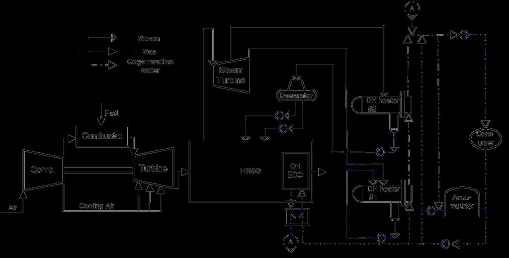
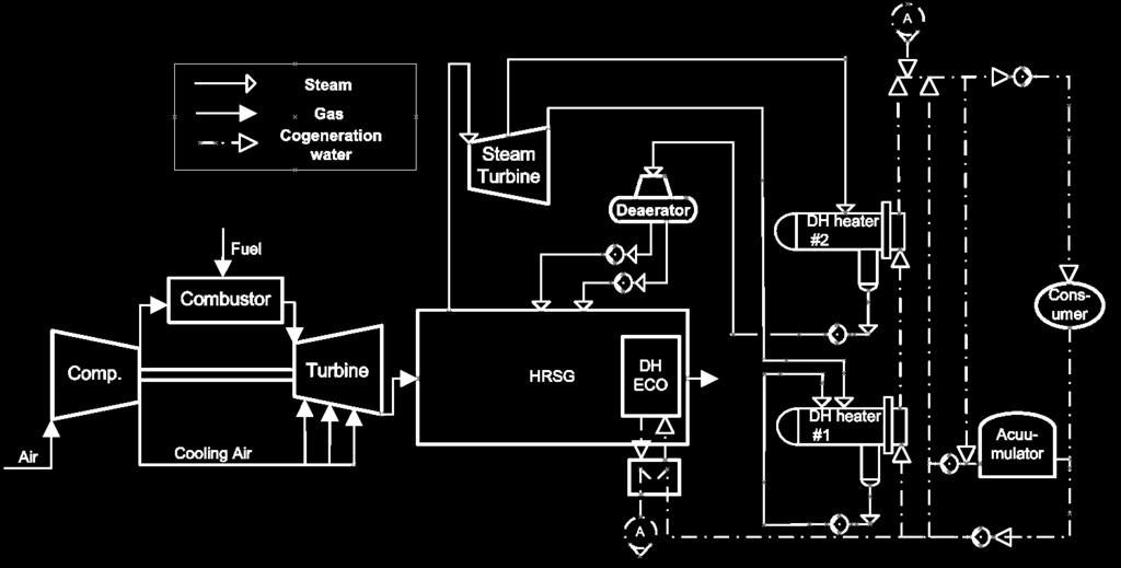
11 System Modeling CHP Plant System Configuration 11


12 System Modeling CHP Plant System Configuration GateCycle R6.1.2, GE Energy,
 12.8 - Total Coolant bleed fraction(%) Unknown 23.5 - Isentropic efficiency (%) Unknown 87.")
13 System Modeling Gas Turbine Modeling Reference Modeling Error(%) Temperature ( ) 5 Set Ambient Pressure(Bar) Set Relative humidity(%) 60 Set Inlet Pressure Drop(mmH 2 O) 76.2 Set Compressor Pressure Ratio Unknown*(12.8) Total Coolant bleed fraction(%) Unknown Isentropic efficiency (%) Unknown Fuel flow rate (kg/hr) Unknown(20400@Curved model) (0.049) Combustor Pressure loss (%) Unknown 5 - Combustion efficiency(%) Unknown Turbine Inlet Temperature ( ) Unknown Turbine Rotor Inlet Temperature ( ) Unknown*(1149) Exhaust temperature ( ) Set Turbine Nozzle Cooling Flow (kg/hr) Unknown (52.57%) - Rotor Cooling Flow (kg/hr) Unknown (47.43%) - Isentropic efficiency (%) Unknown Exhaust gas Performance Fuel Gas flow rate (kg/hr) Exit Pressure Drop (mmh 2 O) Set Power (MW) Thermal efficiency (%) Temperature ( ) 0 Set Lower heating Value (kj/kg) Set Generator Efficiency Unknown 97-13
 807.5 807.5 0.000 Fuel Gas Flow(kg/hr) 7,580 7,676 1.266 Outlet Gas Temperature( ) 761.3 761.3 0.000 HPSH2 Flue Gas Flow(kg/hr) 1,333,180 1,333,275 0.")
14 System Modeling HRSG Modeling Gas side Reference Modeling Error(%) HRSG Inlet Duct Burner Gas Temperature( ) Flue Gas Flow(kg/hr) 1,125,600 1,125, Outlet Gas Temperature( ) Fuel Gas Flow(kg/hr) 7,580 7, Outlet Gas Temperature( ) HPSH2 Flue Gas Flow(kg/hr) 1,333,180 1,333, Energy loss fraction Unknown HPSH1 HPEV HPEC2 LPEV HPEC1 DH ECO Outlet Gas Temperature( ) Energy loss fraction Unknown Outlet Gas Temperature( ) Energy loss fraction Unknown Outlet Gas Temperature( ) Energy loss fraction Unknown Outlet Gas Temperature( ) Energy loss fraction Unknown Outlet Gas Temperature( ) Energy loss fraction Unknown Outlet Gas Temperature( ) Energy loss fraction Unknown
 815.6 815.61 0.001 Surface Area(m 2 ) Unknown 1254.5 - Steam Outlet Temperature( ) 433.9 432.89 0.235 HP DSH Steam Flow Rate(ton/hr) 283.7 283.7 0.000 Cooling Water Flow(ton/hr) 1.")
15 System Modeling HRSG Modeling Steam side Reference Modeling Error(%) Steam Outlet Pressure(kg/cm 2 ) Steam Outlet Temperature( ) HPSH2 Steam Flow Rate(ton/hr) Steam Outlet Enthalpy(kcal/kg) Surface Area(m 2 ) Unknown Steam Outlet Temperature( ) HP DSH Steam Flow Rate(ton/hr) Cooling Water Flow(ton/hr) Steam Outlet Pressure(kg/cm 2 ) Steam Outlet Temperature( ) HPSH1 Steam Flow Rate(ton/hr) Steam Outlet Enthalpy(kcal/kg) Surface Area(m 2 ) Unknown Steam Outlet Pressure(kg/cm 2 ) Steam Outlet Temperature( ) HPEV Steam Flow Rate(ton/hr) Steam Outlet Enthalpy(kcal/kg) Surface Area(m 2 ) Unknown Water Pressure(kg/cm 2 ) Water Outlet Temperature( ) HPEC2 Water Flow Rate(ton/hr) Water Outlet Enthalpy(kcal/kg) Unknown Surface Area(m 2 ) Unknown
 658.4 657.58 0.125 Surface Area(m 2 ) Unknown 10672.6 - Water Pressure(kg/cm 2 ) 104.6 104.6 0.000 Water Outlet Temperature( ) 161.3 161.3 0.")
16 System Modeling HRSG Modeling Steam side (Continued) Reference Modeling Error(%) Steam Pressure(kg/cm 2 ) Steam Outlet Temperature( ) LPEV Steam Flow Rate(ton/hr) Steam Outlet Enthalpy(kcal/kg) Surface Area(m 2 ) Unknown Water Pressure(kg/cm 2 ) Water Outlet Temperature( ) HPEC1 Water Flow Rate(ton/hr) Water Outlet Enthalpy(kcal/kg) Unknown Surface Area(m 2 ) Unknown Water Outlet Temperature( ) Water Outlet Enthalpy(kcal/kg) DH ECO Water Inlet Temperature( ) Water Inlet Enthalpy(kcal/kg) Water Flow Rate(ton/hr) Surface Area(m 2 ) Unknown Water Pressure(kg/cm 2 ) DEA Water Outlet Temperature( ) Water Flow Rate(ton/hr) Aux. Steam Flow Rate(ton/hr) Water Pressure(kg/cm 2 ) Feed Water Water Outlet Temperature( ) Water Flow Rate(ton/hr)
 Mass Flow(ton/hr) 283.7 283.7 0.000 Pressure(ata) Unknown 94.33 - Mass Flow(ton/hr) 0.13 0.13 0.000 Isentropic Efficiency Unknown 0.")
17 System Modeling Steam Turbine Modeling Reference Modeling Error(%) Pressure(ata) Inlet Temperature( ) Enthalpy(kcal/kg) HP Steam Turbine Seal Steam* (HP Turbine Bowl) Mass Flow(ton/hr) Pressure(ata) Unknown Mass Flow(ton/hr) Isentropic Efficiency Unknown HP Steam Turbine Power(kW) Unknown 48,963 - HP Exhaust Pressure(ata) Unknown Pressure(ata) LP Steam Temperature( ) Enthalpy(kcal/kg) LP Steam Turbine LP Extraction (To DH #2) Mass Flow(ton/hr) Pressure(ata) Temperature( ) Enthalpy(kcal/kg) Mass Flow(ton/hr) Isentropic Efficiency Unknown LP Steam Turbine Power(kW) Unknown 20,311 - LP Exhaust Pressure(ata) LP Exhaust Temperature( ) LP Exhaust Enthalpy(kcal/kg) Terminal Power(kW) 67,803 67, Generator Efficiency Unknown

18 System Modeling District Heater 1 Modeling Location Design Data Modeling Error(%) CW Flow 2,706,086 2,709, % CWIN T % CWOUT T % Cooling Water CWIN H % CWOUT H % ΔQ 81,182,580 81,300, % CWIN P % CWOUT P % Inlet P % Main Steam Inlet T % Inlet Flow 161, , % Inlet H % Inlet P Unknown Aux. Steam Inlet T Unknown Inlet Flow 1,300 1, % Inlet H Unknown Inlet P % Cond. Water Inlet T % Inlet Flow 161, , % Inlet H % 18
19 System Modeling District Heater 2 Modeling Location Design Data Modeling Error(%) CW Flow 3,338,051 3,343, % CWIN T % CWOUT T % Cooling Water CWIN H % CWOUT H % ΔQ 92,797,818 93,025, % CWIN P % CWOUT P % Inlet P % Main Steam Inlet T % Inlet Flow 187, , % Inlet H % Inlet P % Aux. Steam Inlet T % Inlet Flow 96,530 96, % Inlet H % Inlet P % Cond. Water Inlet T % Inlet Flow 284, , % Inlet H % 19
20 Introduction System Modeling Results Conclusion
21 Results Performance variation according to DH return Temperature Performance improving by DH return temperature variations District heater of Back pressure turbine may replace the condenser of condensing turbine Steam turbine performance may varied according to the DH return temperature variation 21
22 Power(MW) Results Performance variation according to DH return Temperature Efficiency(%) Power (MW) ST Back Pressure (kpa) CHP System performance variations by DH return temperature variations(system efficiency and Back Pressure variations) ST Power(Fixed Temp.) ST Power(Fixed Heat) System Efficiency(Fixed Temp.) System Efficiency(Fixed Heat) ST Power(Fixed Temp.) ST Power(Fixed Heat) ST Back Pressure(Fixed Temp.) ST Back Pressure(Fixed Heat) Return Temperature( ) Return Temperature ( ) System Power and Efficiency variation vs. Returning Temperature System Power and ST Back Pressure vs. Returning Temperature 22
 110 172.0 1100 Hot Water flow(fixed Temp.) 1,100 Hot Water flow(fixed Heat) Pump Work(Fixed Temp.) 106 170.")
23 Supply Temperature( ) Results Performance variation according to DH return Temperature Supply Heat rate(mw) Water Flow (kg/s) Pump Required Work (kw) CHP System performance variations by DH return temperature variations(district heat and Pump required work variations) Hot Water flow(fixed Temp.) 1,100 Hot Water flow(fixed Heat) Pump Work(Fixed Temp.) Pump Work(Fixed Heat) 900 1, Supply Temperature(Fixed Temp.) Supply Temperature(Fixed Heat) Supply Heat(Fixed Temp.) Supply Heat(Fixed Heat) Return Temperature( ) Return Temperature ( ) Supply Temperature and Heat rate variation vs. Returning Temperature Water Flow rate and Pump Work variation vs. Returning Temperature 23
24 Introduction System Modeling Results Conclusion
25 Conclusion Analyzing CHP Performance by the DH return temperature variation which are varied by the heat consuming pattern CHP Performance are varied by DH Return Temp. variations Steam Turbine power may increases by reduction of condensing pressure Pump required work may decreases by required district heating flow The maintaining supply heat consumption method shows more efficient performance than the maintaining supply temperature Increasing Cooling flow rate for maintaining supply heat consumption may reducing DH supply temperature It bring to increase of steam turbine power Analysis of end user s heat consuming trend based on the real data may requires for more accurate results 25

26 Thank You for Your Attention! Any Questions? KDHC R&D Institute Senior Researcher, Jong Jun Lee leejj1023@kdhc.co.kr leejj1023@gmail.com Office : Cell :