Domestic and International Design Practices, Applications, and Performances of Asphalt/Bituminous Railway Trackbeds
|
|
|
- Gwendoline McCoy
- 5 years ago
- Views:
Transcription


1 Domestic and International Design Practices, Applications, and Performances of Asphalt/Bituminous Railway Trackbeds Dr. Jerry G. Rose, P.E. Professor of Civil Engineering 261 Raymond Building University of Kentucky Lexington, KY Transportation Research Board Presentation January 15-17, 2013 Track Structure Substructure Interaction Session Railroad Track Structure System Design Committee (AR050)

2 Typical Thickness (mm) Classic All-Granular Trackbed
3
 300 150 Ballastless trackbed containing thickened asphalt and subballast")
4 Typical Thickness (mm) Asphalt Underlayment trackbed without granular subballast layers Typical Thickness (mm) Asphalt Combination trackbed containing both asphalt and subballast layers Typical Thickness (mm) Ballastless trackbed containing thickened asphalt and subballast layers
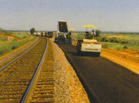
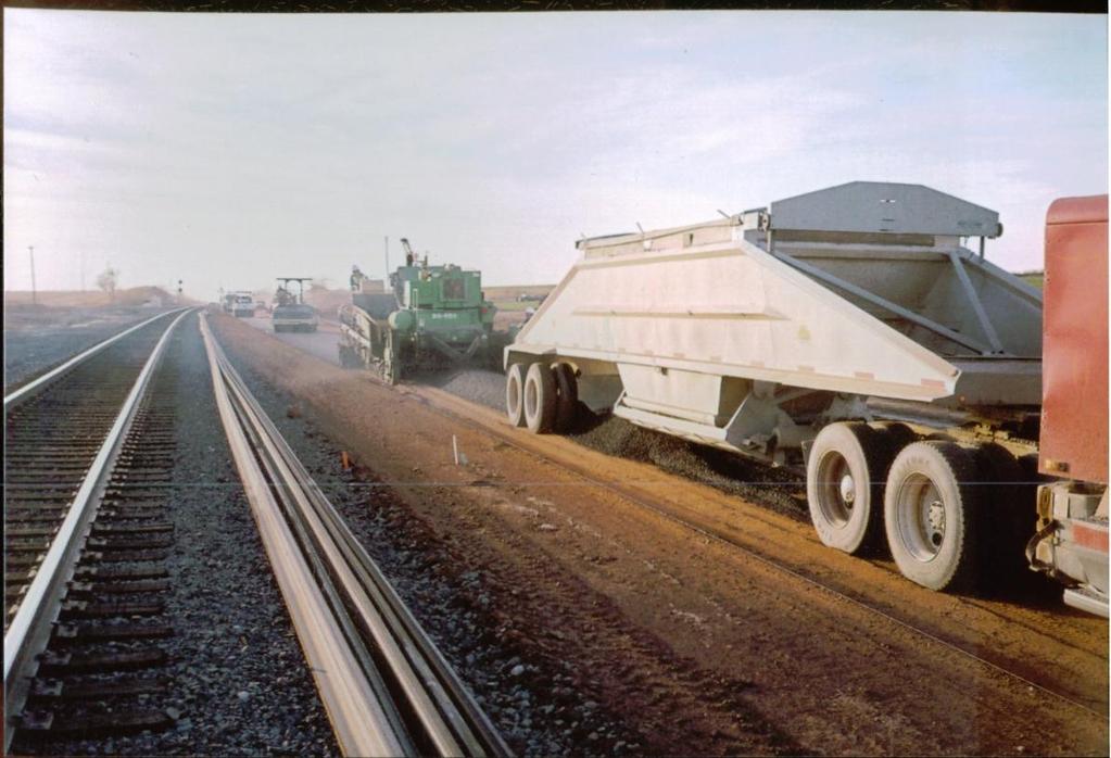
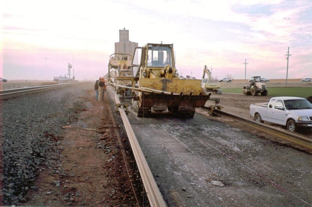
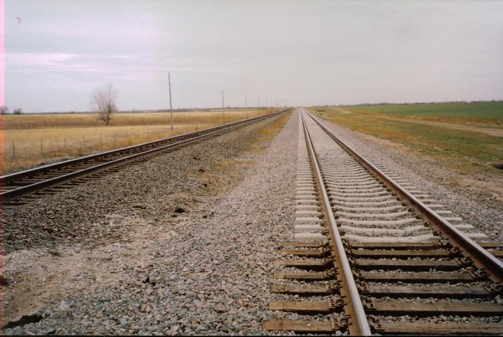
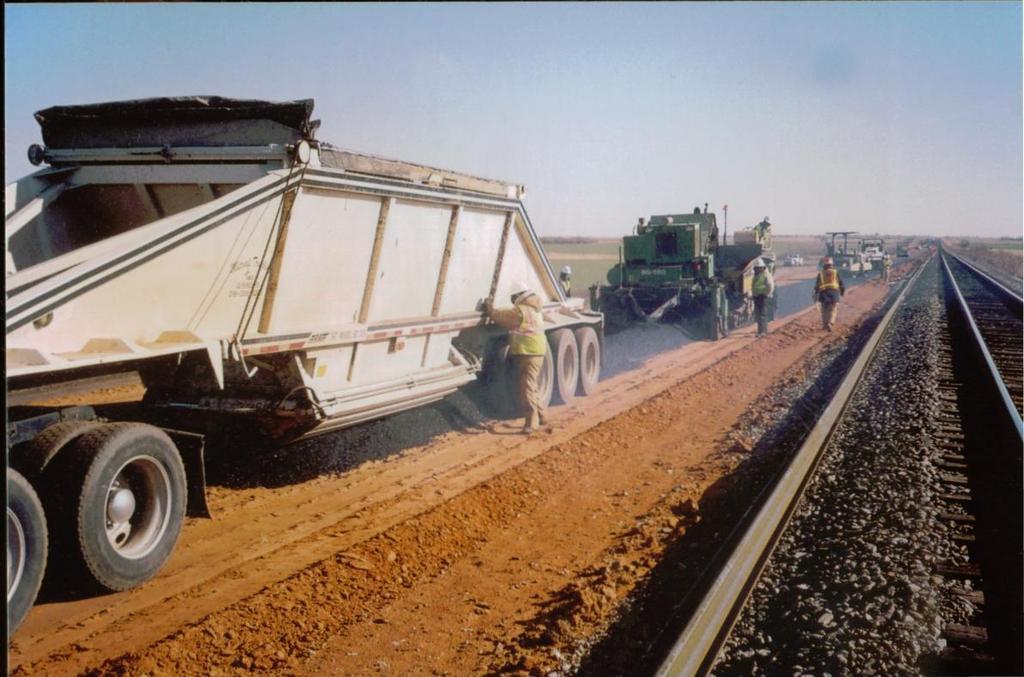
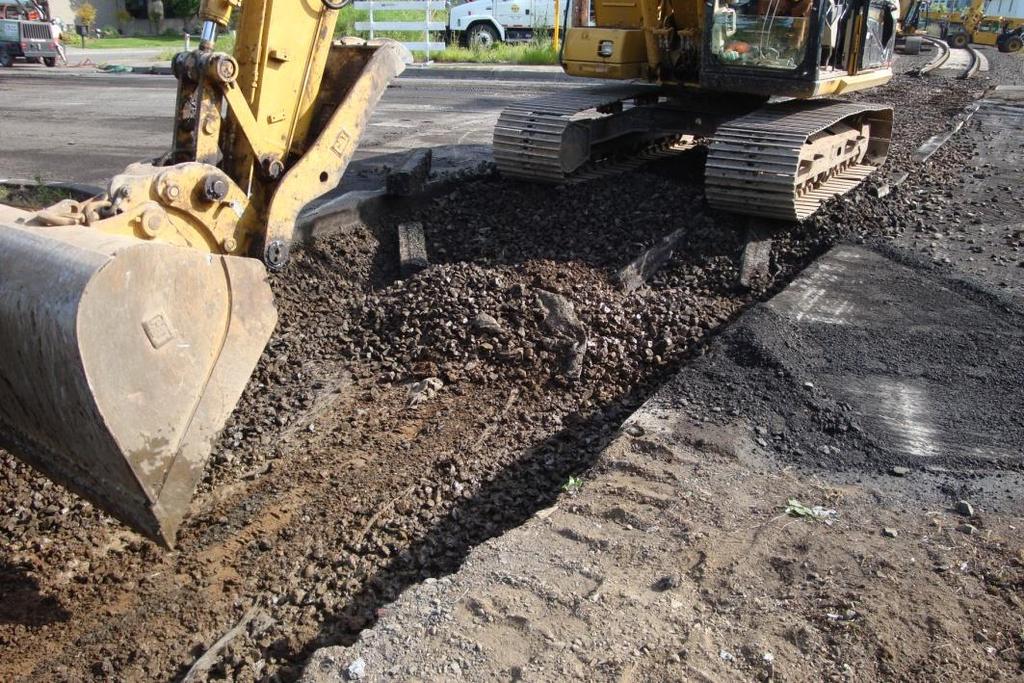
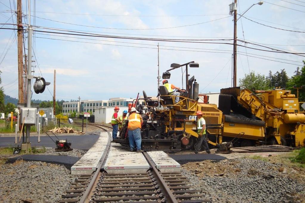
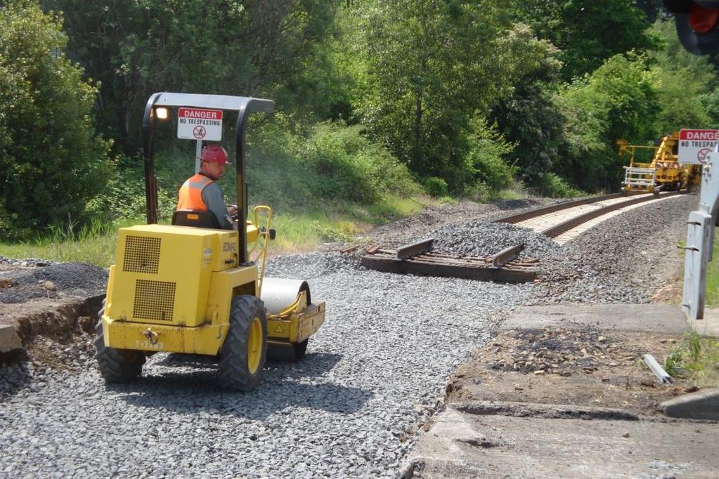
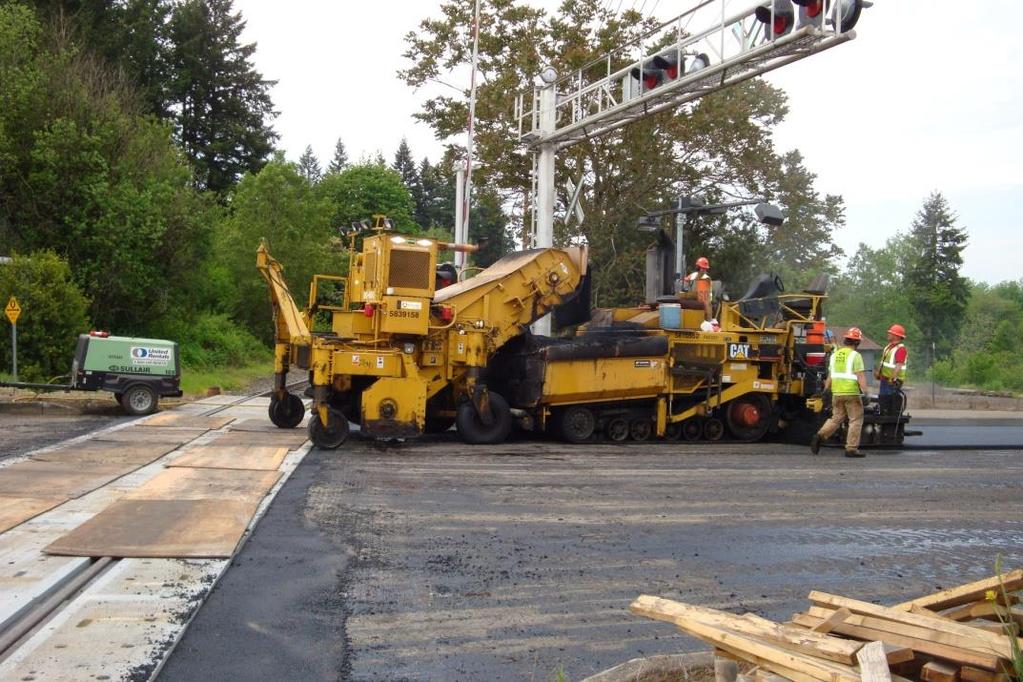
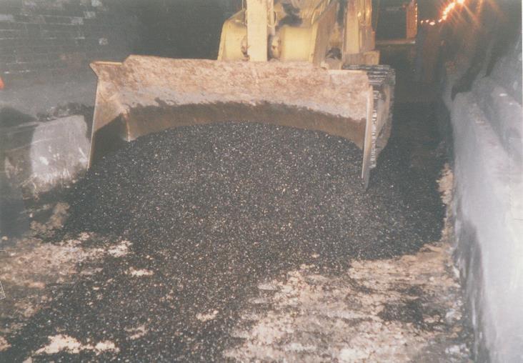
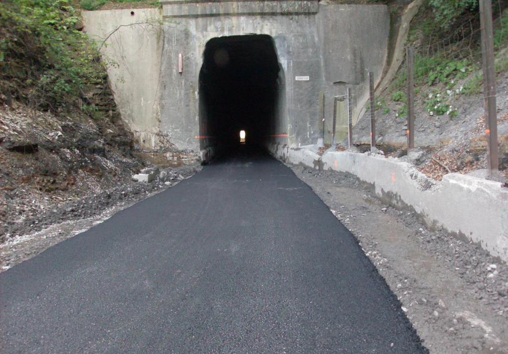
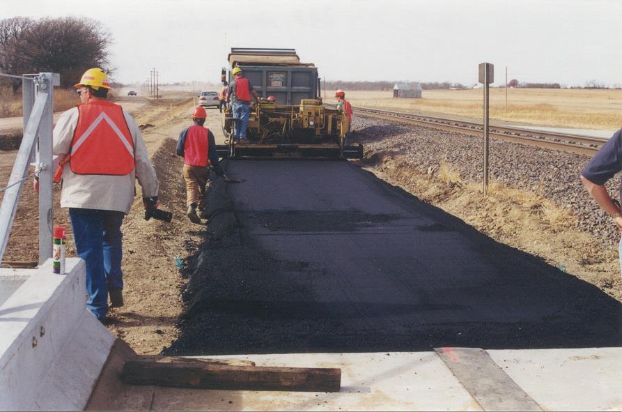
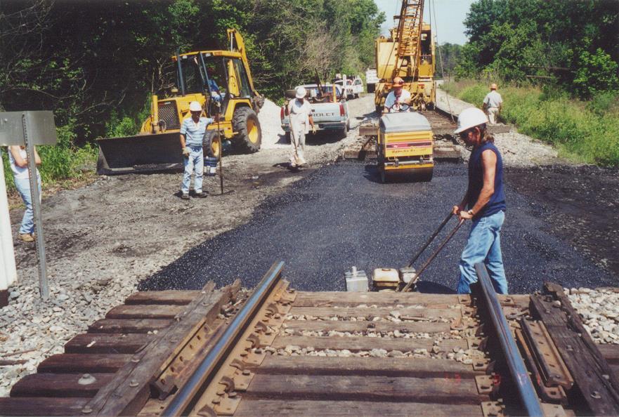
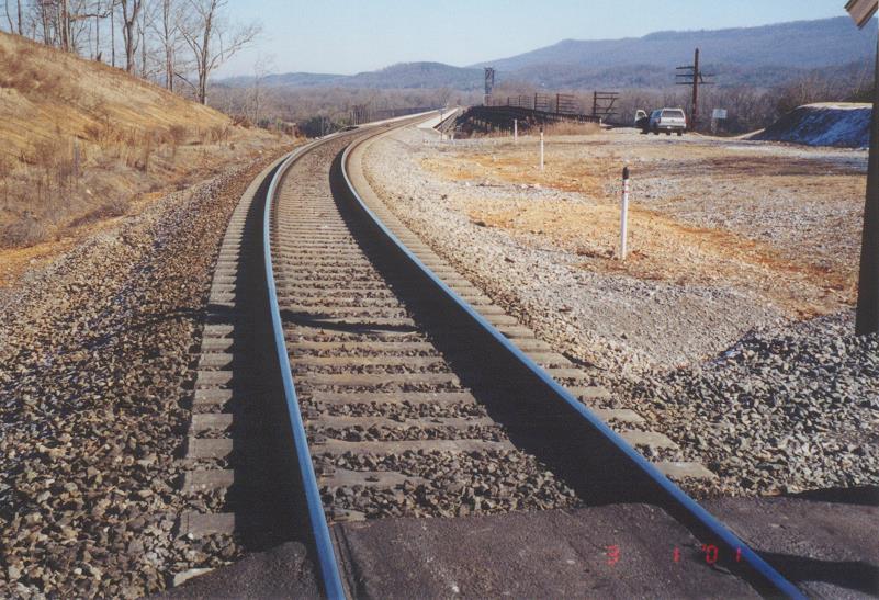
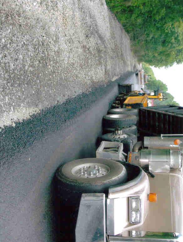
5 United States Applications Since 1981 Short Maintenance Road Crossings, Turnouts, Rail Crossings, Tunnels, Bridge Approaches, WILDS, etc. Capacity Improvement Double Tracking, Line Changes, etc.


6


7


8


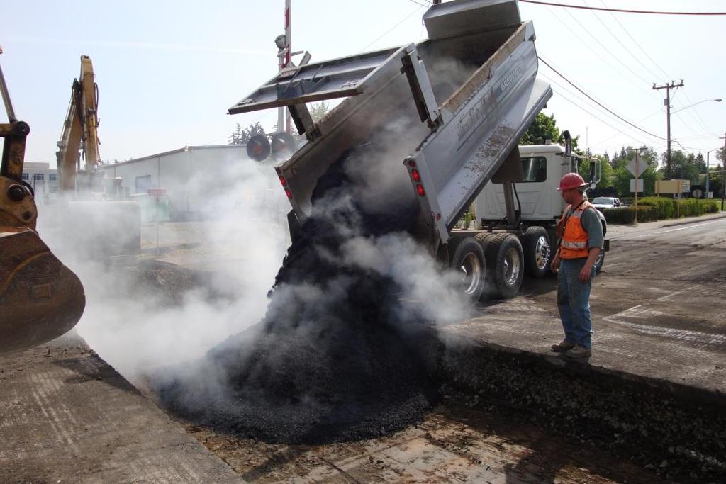
9 SW Durham Rd. May 15-16, 2010

10


11

12


13

14

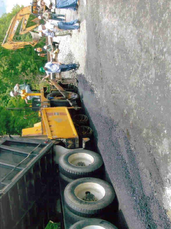
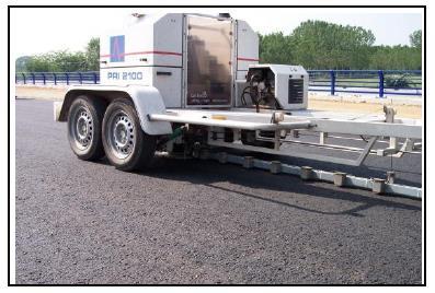
15 Trackbed Measurements & Evaluations


16 Tekscan Sensor Tekscan Sensor Tekscan Sensor Wooden Tie Ballast Geokon Earth Pressure Cell Subballast/HMA Subgrade Geokon Pressure Cell Geokon Pressure Cell


17 Pressure Cell Geokon Model in. Diameter Strain Gage Snap-Master Thermistor Cell Placement on Asphalt
18 Pressure (psi) Empty Coal Train at Conway 20 P-Cell 209 on 5 in. HMA Layer 4 6-Axle Locos Initial 5 Cars Time (s)
19 Stress (psi) Reduction of Dynamic Stresses in. HMA surface Subgrade surface Time (s)

20 Matrix-based array of force sensitive cells Silver conductive electrodes Pressure sensitive ink Conductivity varies Crossing of ink strain gauge View of Tekscan Sensors Tekscan Measurement Configuration

21 Scale in PSI This represents a typical pressure distribution between a machined steel tie plate and the rail with an included rubber bladder.


22 Average Pressure (psi) Positioning of Lead Wheel with Respect to Sensor Ties Before Sensor 8 Ties Before Sensor 6 Tie Before Sensor 4 Ties Before Sensor 2 Ties Before Sensor Directly Above Sensor 2 Ties Past Sensor 4 Ties Past Sensor 6 Ties Past Sensor Lead Wheel Position 8 Ties Past Sensor 10 Ties Past Sensor Snapshot of the Lead Wheel Directly above the Sensor Lead Wheel Over Sensor F = lbf, P = 529 psi


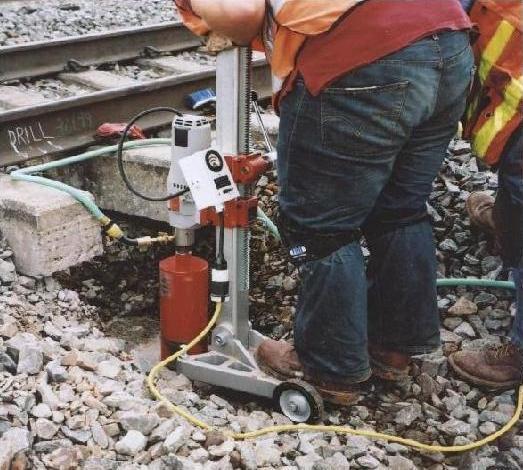
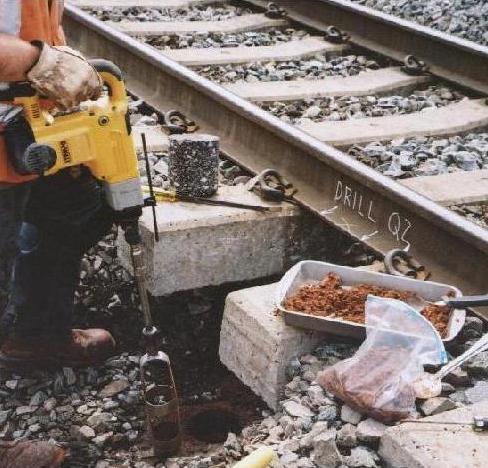
23 Core Drilling
24 Subgrade Findings/Discussion In-situ Moisture Contents Remain Consistent Over Time Compare Favorably With Optimum Assume Unsoaked, Optimum Condition Bearing Capacity Remains At or Near Optimum Wide Range of Subgrades Evaluated Minimum Loading Induced Stress on Subgrade.

25 Asphalt Findings/Discussions Resilient Modulus Values are Intermediate in Magnitude-Typical of Unweathered Asphalt Mixes Asphalt Binders do not Exhibit Excessive Hardening (brittleness), Weathering, Deterioration or Cracking Asphalt is Insulated from Environmental Extremes Asphalt Experiences Minimal Loading Induced Stress Conditions Influencing Typical Failure Modes Experienced by Asphalt Highway Pavements don t Exist in Asphalt Railroads Trackbeds.

26 International Applications Italy France Germany Japan Spain Austria

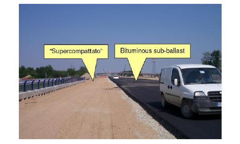
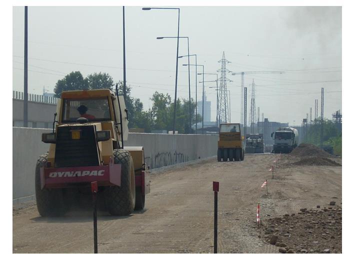
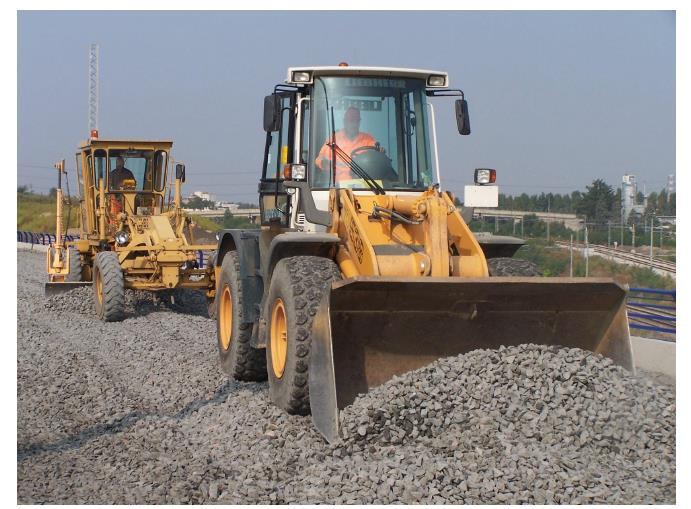
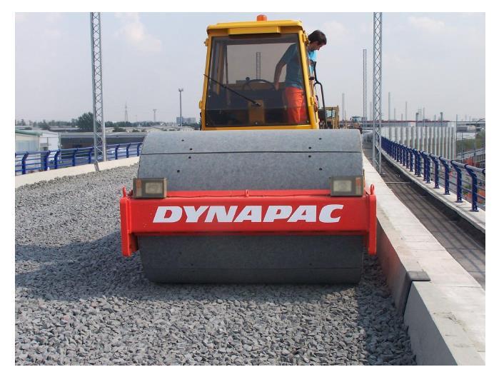
27 Italy Rome-Florence: 252 km ( ) Debated between cement and asphalt Asphalt designated on all future high-speed passenger lines
28 Prevents rainwater from infiltrating the layers below the embankment Eliminate high stress loads and failures of the embankment Protect the upper part of the embankment from freeze/thaw actions Gradually distribute static and dynamic stresses caused by trains Eliminate ballast fouling Buonanno, 2000

29 Typical Cross Section 12 cm of asphalt with 200 MPa modulus 30 cm of super compacted subgrade with 80 MPa modulus 35 cm of ballast on top
30

31 Teixeira, 2005 Policicchio, 2008

32
33

34 Japan Widely Used High Speed/Regular Firm Support for Ballast Reduce Load Level on Subgrade Facilitate Drainage Momoya and Sekine, 2007

35
36 Performance Rank I: Concrete roadbed or asphalt roadbed for ballastless track Concrete base thickness = 190 mm Asphalt base thickness = 150 mm Stone base thickness = 150 mm Performance Rank II: Asphalt roadbed for ballasted track Ballast thickness = mm Asphalt base thickness = 50 mm Stone base thickness = mm Performance Rank III: Crushed stone roadbed for ballasted track

37 Ballastless Cross Section Mainly used for viaducts and tunnels Proposed a low noise solid bed track on asphalt pavement

38 Ballasted Cross Section Asphalt Thickness: 5 cm Well-Graded Crushed Stone Thickness: cm
")
39 France Paris to Strasbourg high-speed line 3 km asphalt subballast 574 km/hr (357mph) (test)

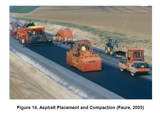
40 Comparative Cross-Sectional Profiles
41

42 Reduces overall cross-sectional thickness by 36 cm Reduces quantity of fill material by 5,000 cubic meters/ kilometer Bitume Info, 2005
43 Testing Conduct tests for 4 years ( ) Temperature sensors continuously recording air temperature Pressure Sensors and Strain Gages checked twice a year Accelerometers

44 Spain Madrid Valladolid Barcelona French Border
45

46

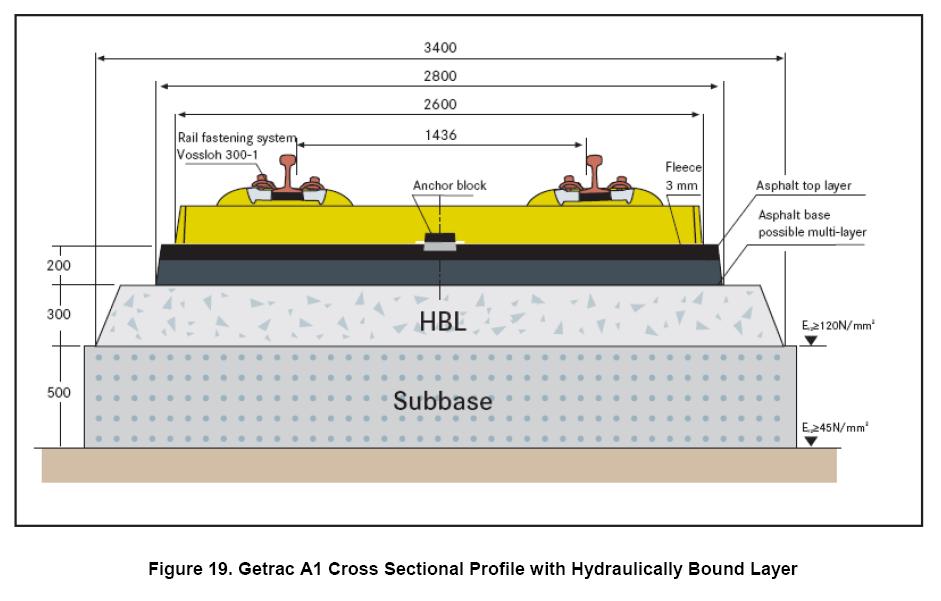
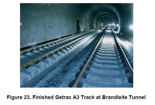
47 Germany Utilize several alternatives to conventional ballast design German Getrac A1/A3 ballastless slab consisting of asphalt Concrete ties are anchored to the asphalt

48
49

50
51
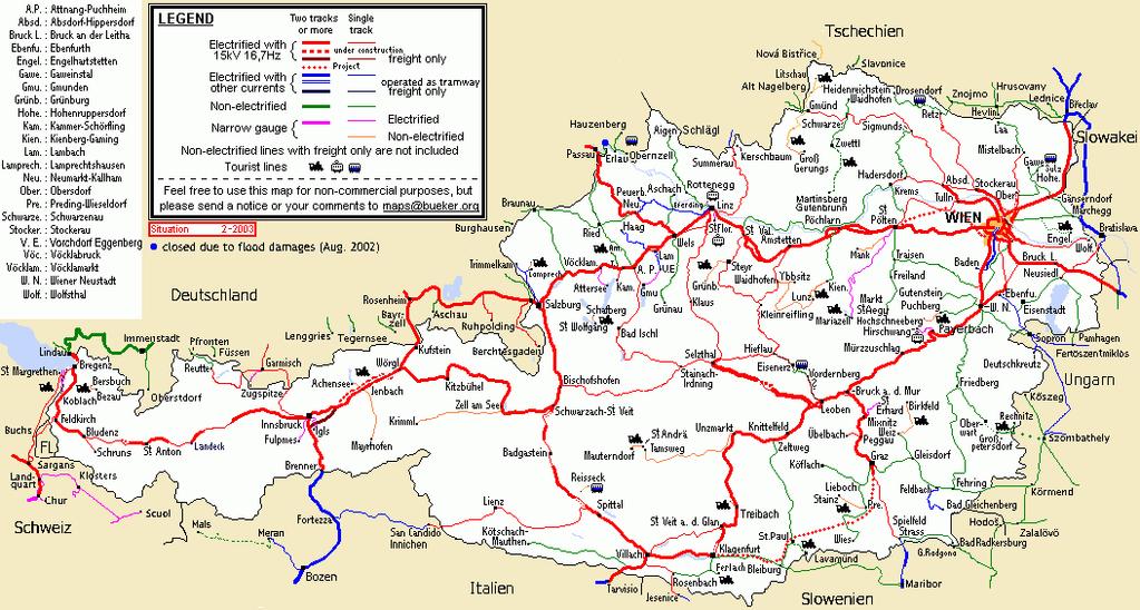
52 Austria

53 Reasons for Implementing Asphalt Layers How to install an Asphalt Layer? Targets of an Asphalt Layer to allow road vehicles running on the sub-layer during construction phase independently from weather and subsoil situation clear separation of sub- and superstructure during the whole service life Advantages drainage effect for raining water hindering it penetrating the substructure avoiding the pumping up of fines into the ballast delivering a certain amount of elasticity homogenising the stresses affecting the substructure

54 Long Term Experiences Jauntal, Carinthia
55 Conclusions Asphalt layers improve the quality of track in defining a clear and long lasting separation between superstructure and substructure. This separation results in less maintenance demands of track and (thus) longer service lives. These benefits must be paid by an additional investment of 10 /m² within the initial construction. Life cycle cost analyses show that it is worth to implement asphalt layers on heavy loaded lines (> 15,000 gt per day and track), as then the annual average track cost can be reduced by 3% to 5%. However, implementation of asphalt layers cannot be proposed for branch lines carrying small transport volumes. Asphalt Layers must be understood as an additional investment in quality, then it pays back its costs. It must not be implemented in order to reduce quality in sub-layers, by for example reducing the thickness of the frost-layers.


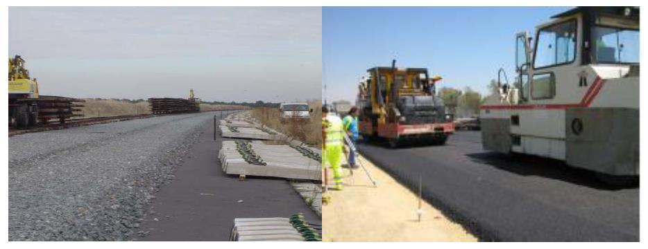
56 Implementation Consequently asphalt layers of 8 cm to 12 cm form a standard element for new high capacity and high speed lines in Austria. Due to the long interruption of operation installing of asphalt layers are not proposed within track re-investment and maintenance operations. picture a to c: new Koralm link, picture d: Schoberpass-line, built in 1991
57 Closure Current Practices Not All-Encompassing Typical Activities