Stellenbosch University, September 2 nd, 2010
|
|
|
- Valerie Clark
- 5 years ago
- Views:
Transcription


1 Solar Hydrogen Stellenbosch University, September 2 nd, 2010 Dr. Christian Sattler DLR German Aerospace Center - Solar Research christian.sattler@dlr.de Slide 1

2 Overview Introduction of DLR Energy Solar Hydrogen From Fossil Recourses Thermochemical Cycles HYDROSOL, HYDROSOL 2, HYDRSOOL 3-D Summary and Outlook Slide 2

3 DLR German Aerospace Center Research Institution Space Agency Project Management Agency Slide 3

4 Research Areas Aeronautics Space Transport Energy Space Agency Project Management Agency Slide 4


 Dortmund Koeln Bonn Lampoldshausen")
5 Locations and employees 6500 employees across 29 research institutes and facilities at 13 sites. Hamburg Bremen Trauen Berlin Braunschweig Neustrelitz Offices in Brussels, Paris, Washington, and Almería (plus permanent Delegation on the Plataforma Solar de Almería) Dortmund Koeln Bonn Lampoldshausen Stuttgart Goettingen Oberpfaffenhofen Weilheim Slide 5
6 Energy Slide 6

7 DLR Energy Research Area DLR Energy Research concentrates on: CO 2 avoidance through efficiency and renewable energies synergies within the DLR major research specific themes that are relevant to the energy economy Second largest research centre in Germany for non-nuclear energy Approx. 400 employees Slide 7

8 Energy Research Program Themes Efficient and environmentally compatible fossil-fuel power stations (turbo machines, combustion chambers, heat exchangers) Solar thermal power plant technology, solar materials conversion Thermal and chemical energy storage High and low temperature fuel cells Systems analysis and technology assessment Slide 8
9 Portfolio of Competences Energy Efficient energy conversion Renewable energies Systems analysis and technology assessment Fuel cells Materials Manufacturing techniques Heat management Fuel cells with alternative fuels Power plant technology Combustion Hybrid power plants Turbo-machines Gas turbine systems Heat exchangers Gas turbines with alternative fuels Heat storage Simulation/modelling Solar gas turbines Solar gas turbines Concentrating solar systems Solar hydrogen production Solar power plants Solar process heat Slide 9
10 Solar Hydrogen Slide 10
11 Vision Producing hydrogen for mass markets means implementing as efficient processes as possible to convert available energy sources like renewables or nuclear into the chemical energy vector. (De Beni G. 1970; Marchetti 1973; Winter 2000) Hydrogen should be produced from water to reduce dependencies on fossil fuels To reduces environmental impact Slide 11
12 Technical and Economic Efficiency Technical: In which process is the most energy stored in the hydrogen Is the process technical feasible? Are there any knock-out criteria? Economic: Is the product (hydrogen) cost competitive? Are there any other economic reasons that make the process not competitive? Slide 12
13 Hydrogen Production Today Steam Methane Reforming Thermal efficiency 78% 1 kg H 2 by means of SMR yields to 9.42 kg of CO 2 The production cost of hydrogen is estimated at 0.04 /kwh (1.33 /kg) Coal Gasification The Lurgi Process (Fixed-Bed) C The Winkler Process (Fluidized-Bed) C The Koppers-Totzek/Texaco Process (Entrained-Bed) C Thermal efficiency 58-63% 23 kg CO 2 / kg H 2 Hydrogen costs from coal gasification are 1.21 to 1.79 /kg H 2 (coal price not reported) Partial Oxidation C /kg Slide 13


14 Solar Thermal Processes for Hydrogen Production Today: Industrial-scale Cheap Not renewable Future: Renewable Expensive Slide 14

15 Production-, Storage- and Infrastructure topics of the European Hydrogen and Fuel Cell JTI Slide 15
16 Solar Hydrogen from Hybrid Fossil Processes Slide 16
17 Carbon Based Transition Processes Starting from applied technologies Reduced risk compared to water splitting technologies Solar Reforming of Natural Gas Development by a number of groups since at least 25 years Cost are estimated to 1.4 /kg H 2 Solar Gasification and Reforming of Petcoke Development by ETH Zurich, CIEMAT, and PDVSA Cost are estimated to about 2.1 /kg H 2 SOLZINC Carbothermal reduction of ZnO Pilot reactor successfully tested Zinc is produced not hydrogen! Solar Cracking of Methane No CO 2 emission but C, C might be a product too challenging reactor design: solids and high temperatures Slide 17
, temperature gradient Approx.")
18 Solar Steam Methane Reforming Technologies decoupled/allothermal indirect (tube reactor) Integrated, direct, volumetric Reformer heated externally (700 to 850 C) Optional heat storage ( up to 24/7) E.g. DLR Project ASTERIX Irradiated reformer tubes (up to 850 C), temperature gradient Approx. 70 % Reformer- Development: CSIRO, Australia and in Japan; Research in Germany and Israel Australian solar gas plant in preparation Quelle: DLR Catalytic active direct irradiated absorber Approx. 90 % Reformer- High solar flux, works only by direct solar radiation DLR coordinated projects: SCR, Solasys, Solref; Research in Israel, Japan Slide 18


 DLR (D), WIS (IL), ETH (CH), Johnson Matthey (UK), APTL (GR),")
19 Direct heated volumetric receiver: SOLASYS, SOLREF (EU FP4, FP6) Pressurised solar receiver, Developed by DLR Tested at the Weizmann Institute of Science, Israel Power coupled into the process gas: 220 kw th and 400 kw th Reforming temperature: between 765 C and 1000 C Pressure: SOLASYS 9 bar, SOLREF 15 bar Methane Conversion: max. 78 % (= theor. balance) DLR (D), WIS (IL), ETH (CH), Johnson Matthey (UK), APTL (GR), HYGEAR (NL), SHAP (I) Slide 19
20 Assessment of relevant H 2 pathways until 2020 including NG Solar-SMR for comparison issues NG NG Grid Electricity Wind Biomass SMR Solar- SMR electrolysis electrolysis H 2 production cost 8* /GJ 12* /GJ 31 /GJ /GJ /GJ Positive impact on security of energy supply modest modest - high high high high Positive impact on GHG emission reduction neutral - modest modest - high negative -neutral high high *assuming a NG price of 4 /GJ; NG Solar-SMR: expected costs for large scale, solar-only Slide 20


21 Project Perspectives The consortium forces the realisation of the a prototype reforming plant Link with Australian CSIRO by an ongoing IPHE project Funding was assured in October 2009 Development phase of the joint project SOLREF receiver will run on a second tower at the CSIRO Solar Centre in Newcastle, NSW Slide 21
22 Thermochemical Cycles Slide 22


23 Thermochemical Water Splitting 2500 C H H O 100 C 0 C C Slide 23


24 PROBLEMS! Hydrogen + Oxygen = explosive gas! Dangerous Separation? 2500 C Materials Special ceramics difficult to handle, expensive 2500 C Temperature How could such high temperatures be achieved? Efficiency? Slide 24
25 Sollution H 2 +O C H C Are the problems solved now? O C Still high temperatures H 2 O Materials H 2 O Chemical reactions Efficiency Slide 25
26 Thermochemical Cycle Firstly developed in the oil crises of the 1970s Use of nuclear energy to produce an energy carrier Mainly in the USA (General Atamics, Westinghouse), but also in Europe (FZJ, JRC Ispra) and Japan (JAEA) Up to 900 different cycles are known Main groups: Sulphur cycles Volatile metal oxide cycles Non-volatile metal oxie cycles Low temperature cycles In the 1980s and 1990s the interst went down because of lower oil prices Come back in the 2000s Solar thermal more in the focus Studies to identify the most promising cycles (e.g. USA, France) Slide 26
27 Thermochemical vs. Electrochemical? Thermochemical No conversion steps necessary = possibly very high efficiency Electrochemical Conversion steps necessary for power production = lower efficiency No contradiction: use energy forms as efficient as possible Slide 27
28 Promising and well researched Cycles Steps Maximum Temperature ( C) LHV Efficiency (%) Sulphur Cycles Hybrid Sulphur (Westinghouse, ISPRA Mark 11) (1150 without catalyst) 43 Sulphur Iodine (General Atomics, ISPRA Mark 16) (1150 without catalyst) 38 Volatile Metal Oxide Cycles Zinc/Zinc Oxide Hybrid Cadmium Non-volatile Metal Oxide Cycles Iron Oxide Cerium Oxide Ferrites Low-Temperature Cycles Hybrid Copper Chlorine Slide 28
29 Temperature nuclear Reactor Type Boiling Water Reactor RBMK (Graphite moderated) CANDU Reactor (Heavy Water Reactor) Pressurised Water Reactor Breeder Reactor, Sodium cooled Advanced Gas Cooled Reactor (Very) High Temperature Reactor Temperature ( C) Carnot-Efficiency 47% 47% 48% 50% 64% 68% 71+% Slide 29


 150 C 50 C")
30 Temperature Concentrating Solar Power 3500 C Paraboloid: Dish 1500 C 400 C Solar tower (Central Receiver System) 150 C 50 C Parabolic trough Slide 30
31 Annual Efficiency of Solar Power Towers Power Tower 100MW th Optical and thermal efficiency / Receiver-Temperature Optical efficiency and thermal annual use efficiency [%] Receiver-Temperature [ C] R.Buck, A. Pfahl, DLR, 2007 Slide 31


32 Solar Towers, Central Receiver Systems Solar-Two PSA PS10+20 Slide 32
33 Efficiency comparison solar H 2 production from water, SANDIA 2008 Process T [ C] Solar plant Solarreceiver + power [MWth] η T/C (HHV) η Optical η Receiver η Annual Efficiency Solar H 2 Elctrolysis (+solarthermal power) NA Actual Solar tower Molten Salt % 57% 83% 14% High temperature steam electrolysis 850 Future Solar tower Particle % 57% 76,2% 20% Hybrid Sulphurprocess 850 Future Solar tower Particle % 57% 76% 22% Hybrid Copper Chlorine-process 600 Future Solar tower Molten Salt % 57% 83% 23% Nickel Manganese Ferrit Process 1800 Future Solar dish Rotating Disc < 1 52% 77% 62% 25% G.J. Kolb, R.B. Diver SAND Slide 33
34 Water based processes Long term necessary for the de-carbonised H 2 society Benchmark: Renewable electricity + electrolysis Challenging technologies Metal/Metal oxide thermo-chemical Cycles Zn/ZnO (3,58 4,12 /kg) Mixed Iron Oxides (Ferrites) Already shown in the HYDROSOL project Cost based on the small scale experiments are 7 /kg Calculated improvements will lead to 3,5 /kg Sulphur Cycle Family Developed for use with nuclear heat Hybrid Sulfur (ISPRA Mark 11) Cost calculation 0,8 /kg H 2 nuclear Sulphur-Iodine Process (ISPRA Mark 16) Cost calculation 1,17 1,66 /kg nuclear, 4,53 /kg solar Slide 34
35 HYDROSOL, HYDROSOL 2, HYDROSOL 3D Slide 35
36 Thermochemical Cycle using Mixed Iron Oxides Process Operation 1. Step: Water Splitting H 2 O + MO red MO ox + H 2 MO H 2red ox H 2 O O C 2. Step: Regeneration MO ox MO red + ½ O 2 MO O 2red ox 1200 C Net reaction: H 2 O H 2 + ½ O 2 Redox materials used in the HYDROSOL-2 project: ZnFeO, NiZnFeO Slide 36

37 Reactor for continuous hydrogen production: Reactor with two modules 15 kw two-chamber system Two different alternating processes: Production: 800 C, water steam, nitrogen, exothermic Regeneration: 1200 C, nitrogen, endothermic Transient steps like Switching between half cycle Start-up / Shutdown Closed system: quartz window Four-way-valve C HO 2 +N 2 HO 2 +N C Slide 37


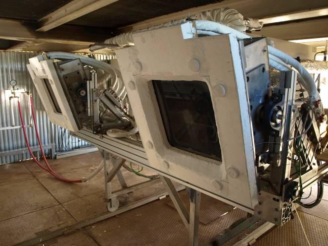

38 HYDROSOL II Pilot Reactor in Operation Slide 38

39 Experiments Process Control Software: Process-Flow-Sheet Regeneration Set parameter Solar Power N 2 N 2 H 2 O Production Slide 39


40 Experiments Process Control Software: Flux Measurement at test operation FluxMax both Modules = 115kW/m 2 Slide 40
41 Results: Thermal cycling Slide 41
42 Hydrogen production of 4th day of experimental series :14:25:00 10:23:35:20 10:32:44:07 10:41:52:96 10:51:02:50 11:00:11:62 11:09:20:68 11:18:29:71 11:27:39:00 11:36:48:32 11:46:05:43 11:56:01:18 12:05:54:21 12:15:39:75 12:25:34:45 12:35:25:87 12:45:16:01 12:55:09:93 13:05:27:85 13:15:38:89 13:25:49:78 13:36:25:34 13:46:39:26 13:57:08:35 14:07:44:28 14:17:45:50 14:28:13:50 14:38:43:34 14:48:38:73 14:59:09:28 15:09:48:46 15:20:15:14 15:30:54:76 15:41:34:09 15:52:11:10 16:02:50:15 16:13:29:14 16:23:59:71 16:34:38:90 16:45:13:87 16:54:56:40 Slide 42 c(h2 ) [%]
43 Summary and Outlook Technologies like solar steam reforming should be short term technologies to introduce solar technology into the chemical industry Thermochemical cycles will provide renewable hydrogen with very high efficiency compared to other renewable technologies The HYDROSOL reactor concept was scaled up in HYDROSOL 2 from the solar furnace to a 100 kw pilot plant on the tower of the PSA Topic of the ongoing HYDROSOL 3-D project is the design of a MW test plant Also sulfur cycles should be scaled-up since the development is already on a very advanced level and the temperature level is lower than of other TCCs Slide 43


44 Acknowledgement The Projects HYDROSOL, HYDROSOL II; HYTHEC, HYCYCLES, Hi2H2, INNOHYP-CA, SOLHYCARB und SOLREF are co-funded by the European Commission HYDROSOL 3-D is co-funded by the European Joint Technology Initative on Hydrogen and Fuel Cells HYDROSOL was awarded Eco Tech Award Expo 2005, Tokyo IPHE Technical Achievement Award 2006 Descartes Research Price 2006 Slide 44

45 Thank you very much for your attention! Slide 45