ACC Users Group 5 th Annual Meeting October 16 th, 2013 Performance Characteristics of a Novel Modular Air-Cooled Condenser
|
|
|
- Ashley Coleen Harmon
- 5 years ago
- Views:
Transcription
1 The Development and Verification of a Novel Modular Air Cooled Condenser for Enhanced Concentrated Solar Power Generation ACC Users Group 5 th Annual Meeting October 16 th, 2013 Performance Characteristics of a Novel Modular Air-Cooled Condenser Presented by: Alan O Donovan (Ph.D. Candidate, University of Limerick)
2 Presentation Overview Project Background Objectives Current Practice in ACCs Measurements on Conventional A-Frame ACC in Ireland Modular ACC (MACC) Design Experimental Measurements on MACC Prototype Air-side characterisation Steam-side characterisation Impact on Plant Output Current Work
 is")

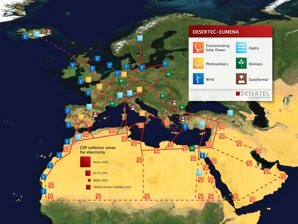
3 Project Background In March 2007 the EU committed to source 20% of Europe's electricity from renewable sources by 2020 Concentrated Solar Power (CSP) is forecasted to provide 25% of this target 630,000 TWh/y of solar radiation falls on the Mediterranean region (Europe consumes just 4,000 TWh/y ~0.6% of available energy)
4

 plan a 25% loss in CSP plant output")
5 Project Background CSP development is being prioritised by EU Barriers to maximising CSP potential Absence of cooling water for condensers in Rankine Cycle Inefficiency of current air-cooling methodologies According to the European Strategic Energy Technology (SET) plan a 25% loss in CSP plant output can occur on warm days


")


6 Project Background For successful deployment of CSP, enhanced aircooling methodologies must be developed Seventh EU Framework programme (FP7) provides funding to successful project proposals MACCSol secured 7m funding in 2010 Consortium consists of 3 universities and 5 industrial partners
7 High level objectives: Objectives Facilitation of EU s 2020 renewable energy target Ensure successful deployment of CSP Elimination of water for cooling CSP condensers Minimise inefficiencies and losses associated with current ACCs Maximise power output from air-cooled CSP plants Ensure CSP is cost-competitive with fossil-fuel based power generation


8 Current Practice in ACCs Steam from turbine Overall height typically 30m Fan: Diameter typically 9m Air flow Large diameter fans are typically two-speed Since the fans are switched in steps, certain deviations upward or downward from the desired set point are unavoidable Fans typically consume 150kW 20 fans for 150 MW plant (Irish Power Plant) 20 x 150kW = 3MW = 2% of plant output Large structures are costly to erect High strain rates can eventually lead to failure


9 Current Practice in ACCs Suspect to wind effects Highly non-uniform flow distribution on air-side Lack of quantitative data available in public domain Flow distribution measurements carried out on A-Frame ACC in a ~400MW plant in Ireland Measurements made using thermistor network

10 Measurements on Conventional ACC Thermistor ACC Street Bank of Thermistors

11 Measurements on Conventional ACC Exit velocity field from ACC cell with single ACC fan operational

12 Measurements on Conventional ACC Heat removal rate from ACC cell with single fan operational


13 Modular ACC Design Modular Air Cooled Condenser MACC Air Flow Direction Axial Fans Steam Flow Direction Array of MACC Modules Modular nature reduced transport, installation & maintenance costs Beneficial for difficult-to-reach places such as desert CSP sites Close proximity of small fans to heat exchanger core ensures uniform air flow over the entire tube bundle Dead-zones arising from flow maldistribution are eliminated
14 Modular ACC Design MACC design incorporates small, speed controllable electric fans Fan speed is continuously variable to maintain optimum condenser conditions irrespective of ambient temperature or steam turbine load Sensors and feedback loop create control algorithm for fans Ability to achieve and maintain an optimum operating point Maximise plant output without over-consumption of fan power Net Power = Gross Power Fan Power


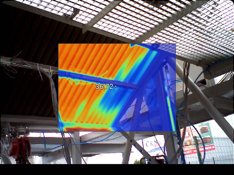
15 Modular ACC Design Full-scale prototype designs have been fabricated and tested on-site in Ireland MACC prototype during testing Steam flow into MACC Steam line Tube bundle/hex Core Walkway Air flow direction Steam In Axial Fans Instrumentation in inlet header HEX Core


16 Modular ACC Design 3 compact heat exchanger designs have been characterised 6 row circular-finned heat exchanger 4 row circular-finned heat exchanger Single row plate-finned heat exchanger

17 Experimental Measurements on Prototypes Measurements carried out in Ireland Test facility to provide slightly superheated steam at approx. 1.5Bar Valve to control steam flow Pressure Reducing Valve Steam Boiler Experimental arrangement was modified to facilitate air-side or steam-side testing
18 Air-Side Characterisation of MACC Quantify aerodynamic and thermal performance of heat exchanger Friction Factor (Pressure Drop) Nusselt Number (Heat Transfer) Empirical correlations are available in literature to predict the performance of various heat exchangers Theory cannot model the complex flow Accuracy of correlations must be verified by experimental means Verification provides confidence in correlations for use in optimisation techniques
19 Air-Side Characterisation of MACC Correlations are used to predict performance from interaction of fan and heat exchanger Intersection of fan curves & resistance curve HEX operating points Flow rates (volumetric, mass, Reynolds number) Pressure drop (friction factor) Nusselt number (air-side heat transfer coefficient)
20 Air-Side Characterisation of MACC Experimental Procedure (Pressure Drop) Fans Tube Bundle Fan software to control and measure fan speed and power consumed Vary fan speed incrementally from 100rpm to 1000rpm Digital manometer to measure pressure Measures pressure differential between heat exchanger and atmosphere
21 Air-Side Characterisation of MACC Experimental Procedure (Heat Transfer) Kays and London test method Q aaaaaa = m cccccccccch ff Slightly superheated steam at inlet Excess steam was forced through to minimise condensate resistance MACC was inclined to promote condensate runoff Isothermal conditions
22 Air-Side Characterisation of MACC Experimental Results Pressure Drop Heat Transfer
23 Steam-Side Characterisation of MACC Quantify the thermal and fluidic performance of the MACC under operational conditions Insight into how the MACC will perform in a power plant Vacuum conditions Air leaks Air-side theory cannot adequately predict condenser performance with condensate-side phenomena such as air leaks, subcooling, etc. Backflow was an issue prominent in the multi-row designs Coupled with air ingress, this lead to non-condensable blanketing

24
25 Steam-Side Characterisation of MACC Experimental Arrangement Solution to air pocket formation dephlegmator (secondary heat exchanger in series with MACC) Excess steam flows from common exit manifold into dephlegmator Condensate flows back into MACC exit manifold Air leaks are continually displaced by downstream vacuum pump to maintain vacuum


26 Backflow is prevented Ensures effective heat transfer area is not reduced Confidence to proceed with testing
27 Steam-Side Characterisation of MACC Experimental Procedure Purge any air present at startup by forcing steam through tubes Confirm isothermal conditions Close system and turn-on fans to 1000rpm Turn-on vacuum pump and open system to dephlegmator Allow for steady-state vacuum Resume steam flow and incrementally decrease fan speed from 1000rpm in steps of 100rpm Measure variation in MACC temperature & pressure
28 Steam-Side Characterisation of MACC Experimental Results Variation of temperature and pressure with fan speed for a range of steam flow rates Results are indicative of how the MACC will be capable of controlling the outlet of a steam turbine in a plant
29 Impact of MACC on Plant Output Determine the effect of installing MACC system on the output of a plant 50MW steam turbine characteristics provided by project partner Only concerned with condenser-turbine relationship All other power block parameters such as turbine inlet temperature and flow rate were assumed constant
30 Impact of MACC on Plant Output Modules 500 Modules 400 Modules C 20 C 30 C 40 C Net Plant Output (MW) Net Plant Output (MW) Fan Rotational Speed (RPM) Fan Rotational Speed (RPM) By increasing fan speed from 200 rpm at 10 C to 600 rpm at 40 C, a 1.5MW loss is avoided


31 Current Work Demonstrator MACC is being fabricated in Ireland and due to be shipped to CSP pilot plant in Australia 1.2MW central tower CSP plant Owned and operated by Vast Solar (part of the Australian Solar Institute) Will be operated for months MACCSol member will be present on site to monitor performance and record data

32 The End Thanks for your time. Any questions/comments? MACCSol team members visiting Gemosolar central tower CSP site in Southern Spain