Dynamics of Wastewater Treatment Systems
|
|
|
- Everett Shaw
- 5 years ago
- Views:
Transcription
1 Dynamics of Wastewater Treatment Systems Gustaf Olsson Lund University, Sweden
2 Models Models for understanding mechanisms design control
3 Mass Balances Conservation of mass: (rate of change of vessel contents) = (rate of inflows) (rate of outflows) + (rate generated) (rate consumed)
4 Simple respirometer The DO (S O ) concentration: ds o = dt Respiration rate r : r = rmax K r o S o + S o
5 Dissolved Oxygen Dynamics
6 DO responses Air flow rate Oxygen concentration
7 Dissolved oxygen dynamics Oxygen transfer rate: rate = K a S S ) L ( O, sat O V DO mass balance: d( VS dt O ) = q S q S + K a ( S S ) V in O, in out O L O, sat O + r V
8 Controlled DO response Air flow rate Change in inlet DO (disturbance) DO conc InletDO conc Change in DO setpoint
9 Controlling the DO response Influencing the K l a K a const u L air u air = u airo + K ( S S O, ref O )
10 Organic carbon removal
11 Carbon removal activated sludge Influent Bio reactor Effluent Aeration Sludge recirculation Sludge outtake
12 Simple nutrient control
13 Simple biological kinetics Process Components Nutrient N Biomass B Kinetics Aerobic heterotrophic growth 1 YB 1 µˆ K N sn + s N X B
14 Simple bioreactor response Biomass Influent substrate decrease Substrate
15 Soluble carbon removal
16 Carbon removal kinetics Process Components Nutrient Oxygen Biomass Kinetics Aerobic heterotrophic growth 1 Y H YH 1 Y H 1 µˆ H K S ss + s S K O so + s O X H Heterotrophic decay 1 f P -1 b H X H
17 Carbon removal response Biomass Decrease in influent substrate Increase in air flow
18 Carbon removal
19 Nitrogen removal
20 Pre-denitrification plant Influent Anoxic reactor Aerobic reactor Effluent Internal recirculation Sludge recirculation Sludge outtake
21 Nitrogen Removal Process Ammonium Dissolved oxygen Nitrification Nitrate Easily degradable organic matter Denitrification Free gaseous nitrogen
22 N removal basic mechanisms
23 Nitrogen removal kinetics Processes Aerobic heterotrophic growth Anoxic heterotrophic growtn Aerobic autotrophic growth Heterotrophic decay Autotrophic Carbon Components Oxygen NH 4 NO 3 Biomass Biomass heterotrophic autotrophic Kinetics decay
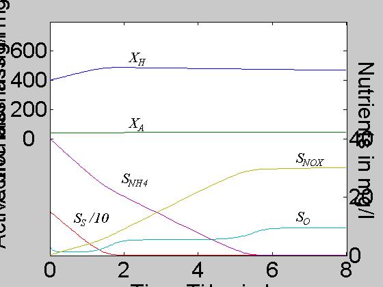
24 Nitrification (batch)
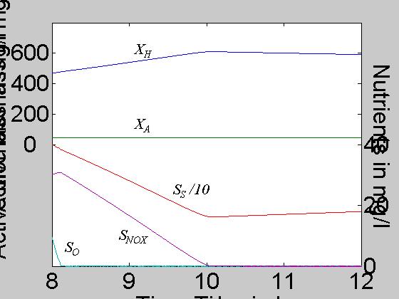
25 Denitrification (batch)
26 Phosphorous removal
27 Plant design for bio-p removal Influent Bio-P reactor Anoxic reactor Aerobic reactor Effluent Internal recirculation Sludge recirculation Sludge outtake
28 P removal Processes Fermentation P release P uptake PAO growth PHA breakdown PP breakdown PAO breakdown Components S F fermentable COD S A volatile fatty acids Dissolved oxygen Phosphate PHA polyhydroxylalkanoates PP polyphosphate PAO
29 P removal basic mechanisms
30 P release basic mechanisms Fermentation of fermentable COD to VFA. VFA used by the organisms to store carbon as poly-hydroxylalkanoates (PHA) P release from poly-phosphate into solution while VFA is converted to PHA
31 P uptake basic mechanisms P uptake from solution to PP using the PHA and DO Growth of PAO biomass, utilizing PHA and DO
32 P removal mechanisms Anaerobic condition: no dissolved oxygen nor nitrate present Aerobic or anoxic conditions: Concnetration nitrate in reactor and/or dissolved oxygen presentcondition PO4-P, ppm Net P uptake Phosphate Accumulating Organism (PAO) PHA storage Accumulated poly phosphate storage PHA storage Accumulated poly phosphate storage Easy degradable organic matter, VFA Phosphate Carbon dioxide Phosphate
33 20 Typical nutrient variations NO3 NH4 PO4 15 NH 4 PO 4 ppm 10 5 NO sep 28-sep 29-sep 30-sep 01-okt 02-okt 03-okt 04-okt 05-okt 06-okt
34 P release
35 P uptake
36 Hydraulic models
37 Simple tank hydraulics q out = const N b α h q in qout Volume V Area A dv dt = A dh dt = q in q out
38 Settling
39 Multilayer model Overflow Layer 1... Feed Layer m-1 Layer m Layer m Layer n Underflow
40 Multilayer model Underflow Solids flux dxi hi Ai qu dt i = m + 1,..., n ( x x ) + A ( f f ) = i 1 i i i 1 C2x f = x v = x C e i i i i i 1 i
41 Settler Feed Flowrate Increase
42 Settler Underflow Decrease
43 Settler Profile 5 layers
44 Settler Profile 10 layers
45 Settler Profile 20 layers
46 General dynamic models
47 State model dx = f ( x( t), u( t), d( t), p) dt y( t) = g ( x( t), u( t), d( t), p) x(t) = state variables u(t) = manipulated input variables d(t) = disturbances input variables y(t) = output variables
48 Input-output models ( ) p t d t u t y h dt dy ), ( ), ( ), ( = ) ( ) (... ) 2 ( ) ( ) (... ) 2 ( ) ( ) ( t v t n t u b t t u b t t b u t n t y a t t y a t t y a t y n n = Time discrete form:
49 Summary Mass balances of substrates, organisms and dissolved oxygen Processes for C, N and P removal Settler dynamics is crucial Many different time scales