Absorption Chillers & Heatpumps
|
|
|
- Marianna O’Neal’
- 5 years ago
- Views:
Transcription


1 AIRCONDITIONING Absorption Chillers & Heatpumps IBK B.V. T +31 (0) Duwboot 19 E info@ibknl.com 3991 CD Houten W


 and KARSE (Korean")


2 water Waste heat ->> Recycle energy Steam Exhaust gas About World Energy World Energy Certificate World Energy has developed and sold various types of heat recovery products. The core product is the Absorption Chiller, which is driven by heat sources like hot water, gas & oil firing, steam, and exhaust gas. World Energy has a wide range of Absorption Chillers and Heat Pumps that can be adapted to the specific needs of customers worldwide. With its technology in development and manufacture of absorption machines meeting international standards, World Energy has provided products for domestic and global markets. World Energy has offered energy efficient products to help Korean industrial area resolve energy challenges, by utilizing the exhaust heat. In cooperation with KDHC (Korean District Heating Corporation) and KARSE (Korean Association of Air Conditioning, Refrigerating and Sanitary Engineers), World Energy has contributed to Korean district cooling and heating industry for the technology development and the introduction of new certification programs. World Energy also has supplied products to major players of fuel cell and cogeneration system industry in America, Asia, Europe and Oceania. World Energy makes every effort to satisfy customers with improving customers business interest by offering energy-saving and environmentally friendly products. ㆍ Quality Management System Certificate ㆍ R&D Center Certificate ㆍ Certificate of Designation of Excellent Product ㆍ Environmental Management System Certificate ㆍ Underwriters Laboratories ㆍ GL Certificate
 May. 2005.")
 Heating Priority Heating Load Increase(CW_in 18.3 C,HW_out 79.")


 (HWAR-LH Series:30~1,00RT) Heat Exchanger Customized to Fuel Cell Jan.")
3 Research & Development Company History Nov Development of Standard COP Absorption Chillers (DW, SW, HAWR-L, S Series) May Developement of 1st Generation Single Effect 2-Lift Driven Absorption Chiller (2AB Series) Heating Priority Heating Load Increase(CW_in 18.3 C,HW_out 79.4 C) < Re> ABS SOL G1 SOL G2 Condensate G2 SOL G1_SAT_Calc. G2_TAR CV2 Open'g CV3 Open'g COOLload CHW_in CHW_out CW_in HEATload HW IN HW OUT Heat'g Heat'g Jan Development of Exhaust Gas Driven Simultaneous Absorption Chiller&Heater Mar UL Listed ( Driven Absorption Chiller) :00:02 15:10:02 15:20:02 15:30:02 15:40:02 Time 15:50:02 16:00:02 16:10:02 16:20:02 16:30:02 Jan Development of Heating Cycle of Single Effect 2-Lift Driven Absorption Chiller Simultaneous Absorption Chiller & Heater Oct Established Certification of 2-Life Driven Absorption Chiller for Korea District Heating Networt Application 1st Generation Single Effect Double Lift Driven Absorption Chiller Sep Cycle upgrade of 1st Generation Single Effect 2-Lift Driven Absorption Chiller (2AB Series:75~1300RT) Jul Development of Heat Exchanger for Fuel cell Dac Complete Development of High COP Absorption Chillers (DWH Series:50~1,500RT) (SWH Series:100~1,500RT) (HWAR-LH Series:30~1,00RT) Heat Exchanger Customized to Fuel Cell Jan Establishment of World Energy Europe Ltd. Maritime Absorption Chiller High COP Single Effect 2-Lift Driven Absorption Chiller Jun Development of Maritime Absorption Chiller Ouc Development of Double Effect 2-Lift Heat Pump for Waste Heat recovery from Sewage Mar Complete Development of 2AB Generation Single Effect 2-Lift Driven Absorption Chiller (2ABH Series:30~1,300RT) 1


4 For Future Energy & Environment Line up World Energy Absorption Chiller Heat source Model No. Type Mode Capacity usrt 20~50 60~80 100~ ~ ~ ~ ~ ~ ~ ~7033 COP Page HWAR-L *** HH Single effect Super High Efficiency 30RT 1300RT 0.83 p.6 HWAR-L *** H Signle effect High efficiency 30RT 1300RT 0.8 p.8 water 2ABH *** Signle effect Double lift High Efficiency 30RT 1300RT 0.71 p.12 2AB *** Single effect Double lift 75RT 1300RT 0.64 p.14 2AA *** Waste heat recovery Single effect 75RT 1300RT 0.41 p.18 DW *** HH Double effect Direct fired type Super High Efficiency Heating 50RT 1500RT 1.32 p.22 Gas Oil DW *** H DW *** Double effect Direct fired type High Efficiency Heating 50RT 1500RT 1.22 p.24 Double effect Direct fired type Heating 50RT 1500RT 1.00 p.26 HPD *** Heat pump Heating 576Mcal/h~4030Mcal/h 1.65 p.50 2
5 WORLD ENERGY World Energy Absorption Chiller Line up Heat source Model No. Type Mode Capacity usrt 20~50 60~80 100~ ~ ~ ~ ~ ~ ~ ~7033 COP Page SWHH *** Double effect Super High Efficiency 100RT 2000RT 1.48 p.30 SWH *** Double effect 100RT 1600RT 1.36 p.32 S *** HH Single effect Steam Super High Efficiency 50RT 2000RT 0.81 p.34 SWM *** Double effect Marine chiller 50RT 1100RT 1.21 p.36 HPS *** Heat pump Heating 576Mcal/h~4030Mcal/h 1.8 p.50 CHP *** H Double effect High Efficiency Heating 50RT 1500RT 1.36 p.40 Exhaust gas CHP *** Double effect 50RT 1500RT 1.2 p.42 Heating water & Exhaust gas CHPL *** H Hybrid chiller 374RT ~1248RT 1.1 ~ 1.23 p.46 3
6 For Future Energy & Environment HWAR-LHH Series Single Effect Driven Absorption Chiller Oullet Condenser Concentrated Pump water Oultlet Absorber Heat Exchanger water inlet Evaporator Absorber Pump Diluted Pump Heat Exchanger Refrigerator Diluted Concentrated Driving 2AA series Condenser Aux. Aux. Concentrated Pump Evaporator Absorber Aux. Absorber Diluted Concentrated Aux. Diluted Aux. Concentrated Pump Diluted Pump Heat Exchanger Aux. Heat Exchanger Aux. Pump water Concentrated Pump 4
7 WORLD ENERGY Single Effect Driven Absorption Chiller 2ABH series 2-Lift water driven absorption chiller has a main cycle and an aux. cycle The chilled water is cooled down twice by refrigerant from double tray in the evaporator and the vaporized refrigerant is absorbed into concentrated solution which is coming from 2nd generator. The quantity of Vapor that can be absorbed in the absorber is increased by double tray system. The concentrated solution becomes diluted solution and the heat is absorbed into cooling water. The diluted solution in absorber flows to 1st generator through low temp. heat exchanger and high temp. heat exchanger, and 95 C hot water heats up the diluted solution and refrigerant is vaporized. absorbent solution becomes intermediate solution in 1st generator and it flows to 2nd generator through high temp. heat exchanger. The intermediated solution in 2nd generator is heated by hot water and refrigerant is vaporized in 2nd generator. The vapor is absorbed into absorbent solution in aux. absorber to become aux. diluted solution. The aux. diluted solution is delivered to aux. generator through aux. heat exchanger, and the solution is heated by hot water coming from 1st generator and becomes aux. concentrated solution. The aux. concentrated solution is delivered to aux. absorber through aux. heat exchanger. The refrigerant vapors which are generated in the 1st generator and aux. generator are condensed in condenser and then flow into evaporator, and the heat in condenser is absorbed by cooling water. 5
8 For Future Energy & Environment Double Single Effect Effect Exhaust Gas Driven Driven Absorption Absorption Chiller Chiller and Heater COP Model Unit L30HH L40HH L50HH L60HH L75HH L90HH L110HH L135HH L155HH L180HH L210HH L240HH L270HH L300HH Capacity ,055 usrt Temp./ Temp. 13 / 8 m 3 /h P. Drop mh 2 O Temp./ Temp. 31 / 36.5 m 3 /h P. Drop mh 2 O Temp./ Temp. 95 / 80 P.Drop ton/h m 3 /h Shell mh 2 O Control Valve mh 2 O Control Valve Power source - 3PH 400V, 50Hz Abs. Pumps (A) 1.5(5.4) 1.8(6.2) 1.9(6.2) 2.4(7.9) Ref. Pump (A) 0.2(1.1) 0.3(1.4) Purge Pump (A) 0.4 ( 1.4 ) Control Panel (A) 0.2 ( 0.5 ) Total Total A Length (L) Width (W) 1,112 1,250 1,363 Height (H) 2,091 2,473 2,705 2,781 Rigging ton Operation ton Space for Tube Replacement 1,900 2,400 3,400 4,600 Volume of Machine Side l Side l ,026 Side l Note 1. Working pressure of each water side is based on 1.0MPa (150psig) 2. Fouling factor m².hr. C/Kcal for Absorber, Condenser and Evaporator. 3. Min. outlet temp. of chilled water: 5 C 4. Min. allowable inlet temp. of cooling water: 20 C. 5. Controllable range shall be 0~100%. 6. Standard Power source is 3ph, 400V, 50Hz and available 220, 380, 440V and 460V power source. 7. Each water flow can be adjusted within 50~120%. 6
9 LHH Series WORLD ENERGY Single Effect Driven Absorption Chiller Model Unit L340HH L375HH L420HH L470HH L525HH L580HH L630HH L750HH L820HH L900HH L975HH L1050HH L1125HH L1300HH Capacity 1,196 1,319 1,477 1,653 1,846 2,039 2,215 2,637 2,883 3,165 3,428 3,692 3,956 4,571 usrt ,050 1,125 1,300 Temp./ Temp. 13 / 8 m 3 /h P. Drop mh 2 O Temp./ Temp. 31 / 36.5 m 3 /h P. Drop mh 2 O Temp./ Temp. 95 / 80 P.Drop ton/h m 3 /h Shell mh 2 O Control Valve mh 2 O Control Valve Power source - 3PH 400V, 50Hz Abs. Pumps (A) 2.4(8.0) 2.8(8.5) 4.5(12.3) 4.5(13.3) 5(15.2) 6.7(20) Ref. Pump (A) 0.4(1.4) 1.5(4.0) Purge Pump (A) 0.4(1.4) 0.75(2.2) Control Panel (A) 0.2 ( 0.5 ) Total Total A Length (L) Width (W) 1,561 1,583 1,833 2,272 2,548 2,930 Height (H) 2,947 3,168 3,474 3,937 4,000 Rigging ton Operation ton Space for Tube Replacement 4,600 5,200 5,700 6,200 6,700 6,200 6,700 6,200 6,700 6,300 6,800 7,800 Volume of Machine Side l ,004 1,060 1,355 1,423 1,795 1,890 2,079 Side l 1,289 1,363 1,462 1,554 2,024 2,147 2,264 2,841 2,993 3,732 3,915 5,664 5,893 6,350 Side l ,023 1,089 1,317 1,397 1,586 Option 1. Non-standard cooling capacity. 2. Higher working pressure (230psig = 1.6MPa, 300psig = 2.0MPa) 3. Special tubes (material) & thickness. 4. Various temp. conditions (CHW, CW, HW) 5. Outdoor installation. 6. The specifications above are subject to change without prior notice for an improvement of the chiller. 7
10 For Future Energy & Environment Double Single Effect Effect Exhaust Gas Driven Driven Absorption Absorption Chiller Chiller and Heater COP 0.8 Model Unit L30H L40H L50H L60H L75H L90H L110H L135H L155H L180H L210H L240H L270H L300H Capacity ,055 usrt Temp./ Temp. 13 / 8 m 3 /h P. Drop mh 2 O Temp./ Temp. 31 / 36.5 m 3 /h P. Drop mh 2 O Temp./ Temp. 95 / 80 P.Drop ton/h m 3 /h Shell mh 2 O Control Valve mh 2 O Control Valve Power source - 3PH 400V, 50Hz Abs. Pumps (A) 1.4(5.2) 1.6(5.1) 1.6(5.3) 1.9(6.2) 1.9(6.3) 2.4(8.0) Ref. Pump (A) 0.2(1.1) 0.3(1.4) 0.4(1.4) Purge Pump (A) 0.4 ( 1.4 ) Control Panel (A) 0.2 ( 0.5 ) Total Total A Length (L) Width (W) 1,062 1,095 1,229 1,472 1,480 Height (H) 1,880 2,255 2,257 2,540 Rigging ton Operation ton Space for Tube Replacement 1,900 2,400 3,400 4,600 Volume of Machine Side l Side l Side l Note 1. Working pressure of each water side is based on 1.0MPa (150psig) 2. Fouling factor m².hr. C/Kcal for Absorber, Condenser and Evaporator. 3. Min. outlet temp. of chilled water: 5 C 4. Min. allowable inlet temp. of cooling water: 20 C. 5. Controllable range shall be 0~100%. 6. Standard Power source is 3ph, 400V, 50Hz and available 220, 380, 440V and 460V power source. 7. Each water flow can be adjusted within 50~120%. 8
11 LH Series WORLD ENERGY Single Effect Driven Absorption Chiller Model Unit L340H L375H L420H L470H L525H L600H L675H L750H L825H L900H L975H L1050H L1125H L1300H Capacity 1,196 1,319 1,477 1,653 1,846 2,039 2,215 2,637 2,883 3,165 3,428 3,692 3,956 4,571 usrt ,050 1,125 1,300 Temp./ Temp. 13 / 8 m 3 /h P. Drop mh 2 O Temp./ Temp. 31 / 36.5 m 3 /h P. Drop mh 2 O Temp./ Temp. 95 / 80 P.Drop ton/h m 3 /h Shell mh 2 O Control Valve mh 2 O Control Valve Power source - 3PH 400V, 50Hz Abs. Pumps (A) 2.4(8.0) 3.7(11.0) 4.2(12.9) 5.2(16.2) 7.5(23.3) Ref. Pump (A) 0.4(1.4) 1.5(4.0) 1.5(4.3) Purge Pump (A) 0.4(1.4) 0.75(2.2) Control Panel (A) 0.2 ( 0.5 ) Total Total A Length (L) Width (W) 1,597 1,836 2,208 2,379 2,929 Height (H) 2,832 3,174 3,600 3,867 4,000 Rigging ton Operation ton Space for Tube Replacement 4,600 5,200 5,700 5,200 5,700 6,200 5,700 6,200 6,700 6,300 6,800 7,800 Volume of Machine Side l ,008 1,074 1,136 1,241 1,313 1,381 1,767 1,862 Side l 1,291 1,370 1,871 2,006 2,131 2,763 2,932 3,111 3,280 3,735 3,939 4,134 5,741 5,988 Side l ,067 1,138 Option 1. Non-standard cooling capacity. 2. Higher working pressure (230psig = 1.6MPa, 300psig = 2.0MPa) 3. Special tubes (material) & thickness. 4. Various temp. conditions (CHW, CW, HW) 5. Outdoor installation. 6. The specifications above are subject to change without prior notice for an improvement of the chiller. 9
12 For Future Energy & Environment Double Single Effect Effect Exhaust Gas Driven Driven Absorption Absorption Chiller Chiller and Heater COP Outline_Foundation L30HH L40HH L50HH L60HH L75HH L90HH L110HH L135HH L155HH L180HH L210HH L240HH L270HH L300HH A B C D E L340HH L375HH L420HH L470HH L525HH L580HH L630HH L750HH L820HH L900H L975HH L1050HH L1125HH L1300HH A B C D E
13 LHH Series WORLD ENERGY Single Effect Driven Absorption Chiller Thermal Insulation 1. Use only Non-inflaable or flame retardant insulation materials. 2. Do not insulate motor of refrigerant pump. 3. Total insulation area is including pipings. 4. Do not cover components such as service valves, diaphragm valves, sight glass, control valves, thermometers or sensor. 5. Use the standard insulation material and thickness as the recoendation 6. For the information of insulation area, please refer to the Table below. 7. The water box sections should be worked to be disassembled for the cleaning or repairing. Note HOT Surface insulation Material of insulation : Inflaable polymer sponge usable at 120 C Thickness of insulation : 19 (3/4 inch), 10 (3/8 inch) when polymer sponge is used COLD Surface insulation Material of insulation : Closed cell type Inflaable polymer sponge Thickness of insulation : 19 (3/4 inch), 10 (3/8 inch) Model Surface(m 2 ) Cold Surface(m 2 ) 19() 10() 19() 10() Model Surface(m 2 ) Cold Surface(m 2 ) 19() 10() 19() 10() L30HH L40HH L50HH L60HH L75HH L90HH L110HH L135HH L155HH L180HH L210HH L240HH L270HH L300HH L340HH L375HH L420HH L470HH L525HH L580HH L630HH L750HH L820HH L900HH 보온부 보냉부 보온부 보냉부 보온부 재생기동체와 워터박스, 재생기열교환기동체와 워터박스, 열교환기재생기동체와워터박스, 열교환기 보온부의입출구 배관 보온부의입출구 배관 보온부의입출구배관 보냉부 증발기동체와 워터박스증발기동체와 워터박스증발기동체와워터박스 냉매펌프의입출구 배관 냉매펌프의입출구 배관 냉매펌프의입출구배관 L975HH L1050HH L1125HH L1300HH Condenser Condenser Condenser Absorber Evaporator Absorber Evaporator Absorber Evaporator Surfaces 19 (3/4 in) : with Box 10 (3/8 in) : Heat Exchanger Body with Piping Cold Surfaces 19 (3/4 in) : Evaporator Body with Box 10 (3/8 in) : and Piping of Pump 11
14 For Future Energy & Environment Double Single Effect Effect Exhaust Gas Driven Driven Absorption Absorption Chiller Chiller and Heater COP Model Unit 2ABH30 2ABH40 2ABH50 2ABH60 2ABH75 2ABH90 2ABH110 2ABH135 2ABH155 2ABH180 2ABH210 2ABH240 2ABH270 2ABH300 Capacity ,055 usrt Temp./ Temp. 13 / 8 m 3 /h P. Drop mh 2 O Temp./ Temp. 31 / 36.5 m 3 /h P. Drop mh 2 O Temp./ Temp. 95 / 55 P.Drop ton/h m 3 /h Shell mh 2 O Control Valve mh 2 O Control Valve Power source - 3PH, 400V, 50Hz Abs. Pumps (A) 2.1 ( 8.2 ) 2.4 ( 9.0 ) 2.6 ( 9.0 ) 3.1 ( 10.7 ) Ref. Pump (A) 0.2 ( 1.1 ) 0.3 ( 1.4 ) Purge Pump (A) 0.4 ( 1.4 ) Control Panel (A) 0.2 ( 0.5 ) Total Total A Length (L) Width (W) Height (H) Rigging ton Operation ton Space for Tube Replacement 1,900 2,400 3,400 4,600 Volume of Machine Side l Side l ,086 1,358 1,450 Side l Note 1. Working pressure of each water side is based on 1.0MPa (150psig) 2. Fouling factor m².hr. C/Kcal for Absorber, Condenser and Evaporator. 3. Min. outlet temp. of chilled water: 5 C 4. Min. allowable inlet temp. of cooling water: 20 C. 5. Controllable range shall be 0~100%. 6. Standard Power source is 3ph, 400V, 50Hz and available 220, 380, 440V and 460V power source. 7. Each water flow can be adjusted within 50~120%. 12
15 2ABH Series WORLD ENERGY Single Effect Driven Absorption Chiller Model Unit 2ABH340 2ABH375 2ABH420 2ABH470 2ABH525 2ABH580 2ABH630 2ABH750 2ABH820 2ABH900 2ABH975 2ABH1050 2ABH1125 2ABH1300 Capacity 1,196 1,319 1,477 1,653 1,846 2,039 2,215 2,637 2,883 3,165 3,428 3,692 3,956 4,571 usrt ,050 1,125 1,300 Temp./ Temp. 13 / 8 m 3 /h P. Drop mh 2 O Temp./ Temp. 31 / 36.5 m 3 /h ,006 1,100 1,207 1,308 1,409 1,509 1,744 P. Drop mh 2 O Temp./ Temp. 95 / 55 P.Drop ton/h m 3 /h Shell mh 2 O Control Valve mh 2 O Control Valve Power source - 3PH, 400V, 50Hz Abs. Pumps (A) 3.2 ( 11.0 ) 3.6 ( 11.5 ) 6.4 ( 18.1 ) 7.5 ( 21.9 ) 8.5 ( 25.7 ) 10.9 ( 32.9 ) Ref. Pump (A) 0.4 ( 1.4 ) 1.5 ( 4.0 ) Purge Pump (A) 0.4 ( 1.4 ) 0.75 ( 2.2 ) Control Panel (A) 0.2 ( 0.5 ) Total Total A Length (L) Width (W) Height (H) Rigging ton Operation ton Space for Tube Replacement 4,600 5,200 5,700 6,200 6,700 6,200 6,700 6,200 6,700 6,300 6,800 7,800 Volume of Machine Side l ,004 1,060 1,355 1,423 1,795 1,890 2,079 Side l 1,755 1,844 1,979 2,102 2,707 2,870 3,026 3,865 4,066 5,182 5,427 7,684 7,991 8,607 Side l ,129 1,211 1,289 1,642 1,745 2,011 2,140 2,648 2,806 3,120 Option 1. Non-standard cooling capacity. 2. Higher working pressure (230psig = 1.6MPa, 300psig = 2.0MPa) 3. Special tubes (material) & thickness. 4. Various temp. conditions (CHW, CW, HW) 5. Outdoor installation. 6. The specifications above are subject to change without prior notice for an improvement of the chiller. 13
16 For Future Energy & Environment Double Single Effect Effect Exhaust Gas Driven Driven Absorption Absorption Chiller Chiller and Heater COP 0.64 Model Unit 2AB75 2AB90 2AB110 2AB135 2AB155 2AB180 2AB210 2AB240 2AB270 2AB300 2AB340 2AB375 Capacity ,055 1,196 1,319 usrt Temp./ Temp. 13 / 8 m 3 /h P. Drop mh 2 O Temp./ Temp. 31 / 36.5 m 3 /h P. Drop mh 2 O Temp./ Temp. 95 / 55 P.Drop ton/h m 3 /h Shell mh 2 O Control Valve mh 2 O Control Valve Power source - 3PH, 400V, 50Hz Abs. Pumps (A) 2.3 ( 7.7 ) 2.3 ( 8.3 ) 2.6 ( 9.1 ) 2.6 ( 9.2 ) 3.2 ( 11 ) Ref. Pump (A) 0.2 ( 1.1 ) 0.3 ( 1.4 ) 0.4 ( 1.4 ) Purge Pump (A) 0.4 ( 1.4 ) Control Panel (A) 0.2 ( 0.5 ) Total Total A Length (L) 2,658 3,678 3,728 4,748 4,872 4,882 Width (W) 1,834 2,109 2,248 2,430 Height (H) 2,084 2,257 2,519 2,787 Rigging ton Operation ton Space for Tube Replacement 2,400 3,400 4,600 Volume of Machine Side l Side l Side l Note 1. Working pressure of each water side is based on 1.0MPa (150psig) 2. Fouling factor m².hr. C/Kcal for Absorber, Condenser and Evaporator. 3. Min. outlet temp. of chilled water: 5 C 4. Min. allowable inlet temp. of cooling water: 20 C. 5. Controllable range shall be 0~100%. 6. Standard Power source is 3ph, 400V, 50Hz and available 220, 380, 440V and 460V power source. 7. Each water flow can be adjusted within 50~120%. 14
17 2AB Series WORLD ENERGY Single Effect Driven Absorption Chiller Model Unit 2AB420 2AB470 2AB525 2AB600 2AB675 2AB750 2AB825 2AB900 2AB975 2AB1050 2AB1125 2AB1300 Capacity 1,477 1,653 1,846 2,110 2,373 2,637 2,901 3,165 3,428 3,692 3,956 4,571 usrt ,050 1,125 1,300 Temp./ Temp. 13 / 8 m 3 /h P. Drop mh 2 O Temp./ Temp. 31 / 36.5 m 3 /h ,063 1,169 1,275 1,382 1,488 1,594 1,842 P. Drop mh 2 O Temp./ Temp. 95 / 55 P.Drop ton/h m 3 /h Shell mh 2 O Control Valve mh 2 O Control Valve Power source - 3PH, 400V, 50Hz Abs. Pumps (A) 5.6 ( 16.8 ) 7.7 ( 23.4 ) 9.4 ( 29.1 ) 12.7 ( 39.2 ) Ref. Pump (A) 0.4 ( 1.4 ) 1.5 ( 4.0 ) 1.5 ( 4.3 ) Purge Pump (A) 0.4 ( 1.4 ) 0.75 ( 2.2 ) Control Panel (A) 0.2 ( 0.5 ) Total Total A Length (L) 4,992 5,534 6,032 5,637 6,135 6,660 6,246 6,771 7,271 7,010 7,510 8,510 Width (W) 2,788 3,140 3,531 4,430 Height (H) 3,036 3,471 3,837 4,000 Rigging ton Operation ton Space for Tube Replacement 4,600 5,200 5,700 5,200 5,700 6,200 5,700 6,200 6,700 6,300 6,800 7,800 Volume of Machine Side l Side l Side l Option 1. Non-standard cooling capacity. 2. Higher working pressure (230psig = 1.6MPa, 300psig = 2.0MPa) 3. Special tubes (material) & thickness. 4. Various temp. conditions (CHW, CW, HW) 5. Outdoor installation. 6. The specifications above are subject to change without prior notice for an improvement of the chiller. 15
18 For Future Energy & Environment Double Single Effect Effect Exhaust Gas Driven Driven Absorption Absorption Chiller Chiller and Heater COP 0.71 Thermal Insulation Surface Cold Surface 19 : 1st with water box, 2nd with water box, Aux. with water box, Heat Exchanger body 10 : Pipes of High temperature s parts 19 : Evaporator with water box 10 : and outlet pipes of refrigerant pump Note 1. Use only Non-inflaable or flame retardants insulatio materials. 2. Do not insulate motor of refrigerant pump. 3. Total insulation area is including pipings. 4. Do not cover components such as service valves, diaphragm valves, sight glass, control valves, thermometers or sensor. 5. Use the standard insulation material and thickness as the recoendation. Condenser Aux. 1 nd Model 2ABH75 Surface(m 2 ) Cold Surface(m 2 ) 19() 10() 19() 10() nd Aux. Absorber Evaporator Absorber 2ABH90 2ABH110 2ABH135 2ABH ABH ABH ABH ABH ABH ABH ABH ABH ABH ABH ABH ABH ABH ABH HOT Surface insulation Material of insulation : Inflaable polymer sponge usable at 120 C Thickness of insulation : 19 (3/4 inch), 10 (3/8 inch) when polymer sponge is used COLD Surface insulation Material of insulation : Closed cell type Non-inflaable polymer sponge Thickness of insulation : 19 (3/4 inch), 10 (3/8 inch) 2ABH900 2ABH975 2ABH1050 2ABH1125 2ABH
19 2ABH Series WORLD ENERGY Single Effect 2-Lift water Driven Absorption Chiller System Piping 1) All external equipment out of the blue line is the customer's scope. 2) Refer to outline drawing and specification data sheet to figure our the external dimensions of the machine, the location & the diameter of water pipe connection and etc. 3) Driving hot water must be maintained as the designed temperature. 4) It is strongly recoended to install shut-off valves at hot water inlet and outlet pipe. 5) The locations of chilled water pumps, cooling water pumps and expansion tanks shall be determined in consideration of the hydrostatic head of pumps and the height of building. And the Machine shall not be subjected to a pressure higher than the designed pressure at any water header. 6) For cooling water quality control, it is recoended to install cooling water bleed-off device on the inlet pipe line of cooling towers. 7) Around 10 meshes of strainers are recoended to be installed in the cooling water line. 8) For the maintenance and the inspection of the machine, the following equipments shall be installed on each chilled water and cooling water inlet/ outlet lines as well as stop valve. Thermometers and pressure gauges shall be installed at chilled and cooling water inlet/outlet. Air relief valves shall be installed on each chilled and cooling water lines at higher points than each water header. Drain valves shall be installed at the lowest position between the shut off valves of chilled and cooling water and the Machine and the drain valve shall be piped to the drain ditch. 9) There shall be a sufficient clearance for access to the absorber, evaporator, condenser, and generator to facilitate inspection and cleaning work. Advantage of 2ABH Series * 14% Less operational cost * 20% Less foot print * 8% Smaller sized water pump & tower * Higher COP at Full load & Part load CW In ( C) Capacity(%) HW out ( C) Aux. cycle Operation COP Part Load rate 2ABH % 55.0 ON % 48.3 OFF % 43.0 OFF % 38.3 OFF % 55.0 ON AB % 47.9 OFF % 42.8 OFF % 38.5 OFF ) CHW is maintained as 8 C and HW inlet as 95 C 2) WB temperature : 27 C 3) Part load rate is according to ARI IPLV Part Load COP COP AB 2ABH 0% 25% 50% 75% 100% Part Load 17
20 For Future Energy & Environment Double Single Effect Effect Exhaust Gas Driven Driven Absorption Absorption Chiller Chiller and Heater COP 0.41 Model Unit 2AA75 2AA90 2AA110 2AA135 2AA155 2AA180 2AA210 2AA240 2AA270 2AA300 2AA340 2AA375 Capacity Temp./ Temp ,055 1,196 1,319 usrt m 3 /h P. Drop mh 2 O Temp./ Temp. m 3 /h P. Drop mh 2 O Temp./ Temp. P.Drop ton/h m 3 /h Shell mh 2 O Control Valve mh 2 O Control Valve Power source - 3PH, 400V, 50Hz Abs. Pumps (A) 3.0 ( 10.8 ) 3.6 ( 12.4 ) 3.8 ( 12.4 ) 4.8 ( 14.8 ) 4.8 ( 16 ) Ref. Pump (A) 0.2 ( 1.1 ) 0.3 ( 1.4 ) 0.4 ( 1.4 ) Purge Pump (A) 0.4 ( 1.4 ) Control Panel (A) 0.2 ( 0.5 ) Total Total A Length (L) Width (W) Height (H) Rigging ton Operation ton Space for Tube Replacement 2,400 3,400 4,600 Volume of Machine Side l Side l ,027 1,135 1,260 1,616 1,725 2,071 2,195 Side l Note 1. Working pressure of each water side is based on 1.0MPa (150psig) 2. Fouling factor m².hr. C/Kcal for Absorber, Condenser and Evaporator. 3. Min. outlet temp. of chilled water: 5 C 4. Min. allowable inlet temp. of cooling water: 20 C. 5. Controllable range shall be 0~100%. 6. Standard Power source is 3ph, 400V, 50Hz and available 220, 380, 440V and 460V power source. 7. Each water flow can be adjusted within 50~120%. 18
21 2AA Series WORLD ENERGY Single Effect 2-Lift Waste Heat Recovery Driven Absorption Chiller Model Unit 2AA420 2AA470 2AA525 2AA580 2AA630 2AA750 2AA820 2AA900 2AA975 2AA1050 2AA1125 2AA1300 Capacity Temp./ Temp. 1,477 1,653 1,846 2,039 2,215 2,637 2,883 3,165 3,428 3,692 3,956 4,571 usrt ,050 1,125 1,300 m 3 /h P. Drop mh 2 O Temp./ Temp. m 3 /h P. Drop mh 2 O Temp./ Temp. P.Drop ton/h m 3 /h Shell mh 2 O Control Valve mh 2 O Control Valve Power source - 3PH, 400V, 50Hz Abs. Pumps (A) 5.6(17) 9.0(24.6) 9.0(16.6) 10.0(30.4) 13.4(40) Ref. Pump (A) 0.4 ( 1.4 ) 1.5 ( 4.0 ) Purge Pump (A) 0.4 ( 1.4 ) 0.75 ( 2.2 ) Control Panel (A) 0.2 ( 0.5 ) Total Total A Length (L) Width (W) Height (H) Rigging ton Operation ton Space for Tube Replacement 5,200 5,700 6,200 6,700 6,200 6,700 6,200 6,700 6,300 6,800 7,800 Volume of Machine Side l ,004 1,060 1,355 1,423 1,795 1,890 2,079 Side l 2,358 2,506 3,123 3,314 3,495 4,561 4,796 6,070 6,356 8,266 8,632 9,363 Side l ,117 1,198 1,274 1,650 1,757 2,047 2,179 2,634 2,794 3,172 Option 1. Non-standard cooling capacity. 2. Higher working pressure (230psig = 1.6MPa, 300psig = 2.0MPa) 3. Special tubes (material) & thickness. 4. Various temp. conditions (CHW, CW, HW) 5. Outdoor installation. 6. The specifications above are subject to change without prior notice for an improvement of the chiller. 19
22 For Future Energy & Environment DWHH Series Cycle Double Effect Direct Fired Absorption Chiller & Heater Vapor Diluted Intermediate Concentrated Heating Cycle Vapor Diluted Intermediate Concentrated 20
23 WORLD ENERGY Double Effect Direct Fired Absorption Chiller & Heater DW Series Cycle Condenser Low Temp. High Temp. Exhaust Gas Change Valve (Close) Evaporator Absorber Change Valve (Close) Vator Diluted Combustion Chamber Intermediate Concentrated Pump Pump Low Temp. High Temp. Heat Exchanger Heat Exchanger Heating Cycle Condenser Low Temp. High Temp. Exhaust Gas Change Valve (Open) Evaporator Absorber Change Valve (Open) Combustion Chamber Vator Diluted Intermediate Concentrated Pump Pump Low Temp. Heat Exchanger High Temp. Heat Exchanger 21
24 For Future Energy & Environment Double Double Effect Effect Exhaust Direct Gas Fired Driven Absorption Chiller Chiller & Heater and Heater COP 1.32 Gas Model Unit DWHH50 DWHH60 DWHH70 DWHH80 DWHH100 DWHH120 DWHH150 DWHH180 DWHH210 DWHH240 DWHH280 DWHH320 DWHH360 Capacity Heating Capacity ,125 1,266 usrt Mcal/h / Temp. 12 /7 m 3 /h P. Drop mh 2 O / Temp / 60 m 3 /h Pressure Drop mh 2 O / Temp. 32 / 37.1 m 3 /h P. Drop mh 2 O High Heating Value kcal/nm 3 10,400 Nm 3 /h Pressure Aq (200Aq) 40 (4000Aq) 50 (4000Aq) Exhaust gas 190x x x x x310 Power source - 3PH, 400V, 50Hz Ref. Pump 0.2(1.1) 0.3(1.5) Abs. Pump Abs. Pump Purge Pump 0.4 Burner Control Pane 0.2 Total Ampere Total A Length (L) 2,245 2,748 2,747 2,771 3,804 3,869 4,919 5,077 Width (W) 1,477 1,615 1,810 1,697 1,792 1,902 2,200 Height (H) 1,760 2,085 2,473 2,705 2,781 Rigging ton Operation ton Space for Tube Replacement 1,900 2,400 3,400 4,600 Note 1. Working pressure of each water side is based on 1.0MPa (150psig) 2. Fouling factor m².hr. C/Kcal for Absorber, Condenser and Evaporator. 3. Min. outlet temp. of chilled water: 5 C 4. Min. allowable inlet temp. of cooling water: 20 C. 5. Controllable range shall be 25~100%. 6. Standard Power source is 3ph, 400V, 50Hz and available 220, 380, 440V and 460V power source. 7. Each water flow can be adjusted within 50~120%. 22
25 DWHH Series WORLD ENERGY Double Effect Direct Fired Absorption chiller & Heater Gas Model Unit DWHH400 DWHH450 DWHH500 DWHH560 DWHH630 DWHH700 DWHH800 DWHH900 DWHH1000 DWHH1100 DWHH1200 DWHH1300 DWHH1400 DWHH1500 Capacity Heating Capacity 1,407 1,582 1,758 1,969 2,215 2,461 2,813 3,165 3,516 3,868 4,220 4,571 4,923 5,274 usrt ,000 1,100 1,200 1,300 1,400 1, ,043 1,159 1,298 1,460 1,622 1,854 2,086 2,318 2,549 2,781 3,013 3,245 3,476 Mcal/h ,116 1,256 1,395 1,594 1,794 1,993 2,192 2,392 2,591 2,790 2,990 / Temp. 12/7 m 3 /h P. Drop mh 2 O / Temp / 60 m 3 /h Pressure Drop mh 2 O / Temp. 32 / 37.1 m 3 /h ,000 1,100 1,200 1,300 1,400 1,500 P. Drop mh 2 O High Heating Value kcal/nm 3 10,400 Nm 3 /h Pressure Aq (4000Aq) 65 (4000Aq) Exhaust gas 410x x x x900 Power source - 3PH, 400V,50Hz Ref. Pump 0.3(1.5) 0.4 (1.5) 1.5 (4.0) Abs. Pump Abs. Pump Purge Pump Burner Control Pane 0.2 Total Ampere Total A Length (L) ,739 6,219 6,231 6,836 7,336 6,829 7,449 6,920 7,420 7,197 7,697 Width (W) 2,200 2,510 2,760 2,410 3,281 3,281 3,290 3,880 4,420 Height (H) 2,781 2,950 3,068 3,500 3,940 4,000 Rigging ton Operation ton Space for Tube Replacement ,200 5,700 6,700 6,700 6,300 6,700 6,300 6,700 6,300 6,700 Option 1. Non-standard cooling capacity. 2. Higher working pressure (230psig = 1.6MPa, 300psig = 2.0MPa) 3. Special tubes (material) & thickness. 4. Various temp. conditions (CHW, CW, HW) 5. Outdoor installation. 6. The specifications above are subject to change without prior notice for an improvement of the chiller. 23

26 For Future Energy & Environment Double Double Effect Effect Exhaust Direct Gas Fired Driven Absorption Chiller Chiller & Heater and Heater COP 1.22 Gas Model Capacity Heating Capacity / Temp. Pressure Drop / Temp. Pressure Drop / Temp. Pressure Drop High Heating Value Pressure Exhaust gas Power source Ref. Pump Abs. Pump1 Abs. Pump2 Purge Pump Burner Control Panel Total Tatal Amp. Length (L) Width (W) Height (H) Rigging Operation Space for Tube Replacement Unit usrt kcal/h m 3 /h mh 2 0 m 3 /h mh 2 0 m 3 /h mh 2 0 m kcal/nm 3 Nm 3 /h Aq - A ton ton DWH50 DWH60 DWH70 DWH80 DWH100 DWH120 DWH150 DWH180 DWH210 DWH240 DWH280 DWH320 DWH360 DWH ,125 1,266 1, / , , (200Aq) 180 x x 150 2,095 1, ,598 1, , ,597 1, (4,000Aq) 280 x 210 3PH, 400V, 50Hz , / / , ,680 1, ,400 4, ,708 2, , x (4,000Aq) 360 x ,734 2, , ,776 2,270 2, Note 1. Working pressure of each water side is based on 1.0MPa (150psig) 2. Fouling factor m².hr. C/Kcal for Absorber, Condenser and Evaporator. 3. Min. outlet temp. of chilled water: 5 C 4. Min. allowable inlet temp. of cooling water: 20 C. 5. Controllable range shall be 25~100%. 6. Standard Power source is 3ph, 400V, 50Hz and available 220, 380, 440V and 460V power source. 7. Each water flow can be adjusted within 50~120%. 24
27 DWH Series WORLD ENERGY Double Effect Direct Fired Absorption chiller & Heater Gas Model Capacity Heating Capacity / Temp. Pressure Drop / Temp. Pressure Drop / Temp. Pressure Drop High Heating Value Pressure Exhaust gas Power source Ref. Pump Abs. Pump1 Abs. Pump2 Purge Pump Burner Control Panel Total Tatal Amp. Length (L) Width (W) Height (H) Rigging Operation Space for Tube Replacement Unit usrt kcal/h m 3 /h mh 2 0 m 3 /h mh 2 0 m 3 /h mh 2 0 m kcal/nm 3 Nm 3 /h Aq - A ton ton DWH450 DWH500 DWH560 DWH630 DWH700 DWH800 DWH900 DWH1000 DWH1100 DWH1200 DWH1300 DWH1400 DWH1500 1, , , ,211 1, , ,357 1, , ,526 1, , ,696 1, , ,938 1, / / , , , (4,000Aq) 65 (4,000Aq) 410 x x x x 900 3PH, 400V, 50Hz ,880 4,998 5,540 6,038 5,644 6,142 6,667 2,469 2,935 3,330 2,633 2,962 3, ,500 5,200 5,700 5,200 5,700 6,200 3,165 3,516 3,868 4,220 4, ,000 1,100 1,200 1,300 2,181 2,423 2,665 2,907 3,510 1,876 2,084 2,292 2,500 3, / ,923 5,274 1,400 1,500 3,392 3,634 2,917 3, ,100 1,200 1,300 1,400 1, ,293 6,818 7,318 6,860 7,360 3,929 3,500 4,460 3, ,700 6,200 6,700 6,200 6,700 Option 1. Non-standard cooling capacity. 2. Higher working pressure (230psig = 1.6MPa, 300psig = 2.0MPa) 3. Special tubes (material) & thickness. 4. Various temp. conditions (CHW, CW, HW) 5. Outdoor installation. 6. The specifications above are subject to change without prior notice for an improvement of the chiller. 25
28 For Future Energy & Environment Double Double Effect Effect Exhaust Direct Gas Fired Driven Absorption Chiller Chiller & Heater and Heater COP 1.00 Gas Diesel Boiler 모델 Capacity Heating Capacity / Temp. P. Drop / Temp. Pressure Drop / Temp. P. Drop High Heating Value Pressure Exhaust gas Power source Ref. Pump Abs. Pump Purge Pump Burner Control Pane Total Ampere Total Length (L) Width (W) Height (H) Rigging Operation Space for Tube Replacement High Heating Value Flow Rate Oil piping connection size Exhaust gas 단위 usrt Mcal/h m 3 /h mh 2 0 m 3 /h mh 2 0 m 3 /h mh 2 0 kcal/nm 3 Nm 3 /h Aq - A ton ton kcal/ /h A DW50 DW60 DW70 DW80 DW100 DW120 DW150 DW180 DW210 DW240 DW280 DW320 DW360 DW ,125 1,266 1, ,056 1, , / / / , ,000 50(200Aq) 40(4,000Aq) 50(4,000Aq) 190 X X X X X 310 3PH, 400V, 50Hz ,095 2,598 2,597 3,680 3,708 4,734 4,776 1,477 1,615 1,810 1,920 2,100 2,200 2,290 1,760 2,090 2,122 2, ,900 2,400 3,400 4,500 10, A*2 20A*2 190 X X X X X 310 Note 1. Working pressure of each water side is based on 1.0MPa (150psig) 2. Fouling factor m².hr. C/Kcal for Absorber, Condenser and Evaporator. 3. Min. outlet temp. of chilled water: 5 C 4. Min. allowable inlet temp. of cooling water: 20 C. 5. Controllable range shall be 25~100%. 6. Standard Power source is 3ph, 400V, 50Hz and available 220, 380, 440V and 460V power source. 7. Each water flow can be adjusted within 50~120%. 26
29 DW Series WORLD ENERGY Double Effect Direct Fired Absorption chiller & Heater Gas Diesel Boiler Model Capacity Heating Capacity / Temp. P. Drop / Temp. Pressure Drop / Temp. P. Drop High Heating Value Pressure Exhaust gas Power source Ref. Pump Abs. Pump Purge Pump Burner Control Pane Total Ampere Total Length (L) Width (W) Height (H) Rigging Operation Space for Tube Replacement High Heating Value Flow Rate Oil piping connection size Exhaust gas Unit usrt Mcal/h m 3 /h mh 2 0 m 3 /h mh 2 0 m 3 /h mh 2 0 kcal/nm 3 Nm 3 /h Aq - A ton ton kcal/ /h A DW450 DW500 DW560 DW630 DW700 DW800 DW900 DW1000 DW1100 DW1200 DW1300 DW1400 DW1500 1,582 1,758 1,969 2,215 2,461 2,813 3,165 3,516 3,868 4,220 4,571 4,923 5, ,000 1,100 1,200 1,300 1,400 1,500 1,320 1,467 1,643 1,848 2,054 2,347 2,641 2,934 3,227 3,521 3,814 4,108 4,401 1,135 1,262 1,413 1,590 1,766 2,019 2,523 2,271 2,523 2,776 3,280 3,532 3, / / / ,000 1,100 1,200 1,300 1,400 1, , ,000 50(4,000Aq) 65(4,000Aq) 410 X X X X 900 3PH, 400V, 50Hz ,880 4,998 5,540 6,038 5,644 6,142 6,667 6,293 6,818 7,318 6,860 7,360 2,490 3,055 3,330 3,738 4,460 2,633 2,962 3,310 3,500 3, ,500 5,200 5,700 5,200 5,700 6,200 5,700 6,200 6,700 6,200 6,700 10, A*2 25A*2 32A*2 410 X X X X 900 Option 1. Non-standard cooling capacity. 2. Higher working pressure (230psig = 1.6MPa, 300psig = 2.0MPa) 3. Special tubes (material) & thickness. 4. Various temp. conditions (CHW, CW, HW) 5. Outdoor installation. 6. The specifications above are subject to change without prior notice for an improvement of the chiller. 27
30 For Future Energy & Environment Steam Driven Absorption Chiller SWHH Series Condenser Low Temp. High Temp. Steam Pump 2 Condensed Steam Trap Evaporator Drain Absorber Drain Heat Reclaimer Vapor Diluted Intermediate Concentrated Pump Pump Low Temp. Heat Exchanger High Temp. Heat Exchanger Steam Absorption chiller is composed of evaporator, absorber, condenser, low/ high temp. generator, low/ high tem. heat exchanger, solution pump #1&2, refrigerant pump, Drain Heat Reclaimer. water temp. goes down in the evaporator and steam from evaporator is absorbed into the concentrated solution in absorber. Diluted solution in absorber flows into the High Temp. by solution pump through low temp./high temp. heat exchanger and it is heated by steam to become intermediated solution. Concentrated Intermediate solution in the low temp. generator exchanges it's heat in the low/high heat exchanger, low temp. solution flow back to absorber and repeat the process. Steam in the high temp. generator exchanges It's heat twice in the chiller, firstly in the high temp. generator and secondly in Drain Heat reclaimer, therefore high temp. steam drains out at low temp. like 95 C. This Process can increase heat recovery rate and chiller capacity 28
31 WORLD ENERGY Low Temp. Condenser High Temp. Steam Driven Absorption Chiller Steam Pump 2 SWH Series Condensed Condenser Low Temp. High Temp. Steam Pump2 Absorber Heat Exchanger Steam Trap CHX Drain Evaporator Absorber Evaporator Absorber Steam Drain Heat Trap Reclaimer Vapor Diluted Vapor Intermediate Drain Diluted Concentrated Intermediate Concentrated Pump SHH Series Pump Pump Condenser Condenser Condenser Steam Pump1 Low Temp. Low Temp. High Temp. Drain Heat Heat Exchanger Reclaimer Heat Exchanger Heat Exchanger Low Temp. Low Temp. Low Temp. Steam Steam High Temp. High Temp. High Temp. Steam Steam Steam Pump 2 Pump 2 Pump 2 Condensed High Temp. Heat Exchanger water Condensed Condensed Condenser Steam Drain Trap Steam Trap Steam Trap Absorber Heat Exchanger Absorber Heat Exchanger Pump2 Absorber Heat Exchanger water Absorber Heat Exchanger Evaporator water Evaporator Evaporator Absorber Absorber Evaporator Absorber Absorber Drain Heat Reclaimer Drain Heat Reclaimer Drain Heat Reclaimer water Intermediate Vapor Diluted Diluted Concentrated Pump Pump1 Pump Pump Pump Low Temp. High Temp. Heat Exchanger Heat Exchanger Heat Exchanger Low Temp. High Temp. Heat Exchanger Heat Exchanger Low Temp. High Temp. Heat Exchanger Heat Exchanger Vapor Vapor Diluted Pump Pump Pump Drain Drain Drain Intermediate Concentrated Diluted Concentrated Intermediate Concentrated Steam Steam Steam Steam 29
32 For Future Energy & Environment Double Effect Exhaust Steam Driven Gas Driven Absorption Absorption Chiller Chiller and Heater COP 1.48 Model Unit SWHH100 SWHH120 SWHH150 SWHH180 SWHH210 SWHH240 SWHH280 SWHH320 SWHH360 SWHH400 SWHH450 SWHH500 Capacity ,125 1,266 1,407 1,582 1,758 usrt / Temp. 12 / 7 Steam m 3 /h P. Drop mh 2 O / Temp. 32 / 37.1 m 3 /h P. Drop mh 2 O Pressure MPa 0.8 Kg/h ,005 1,149 1,292 1,436 1,616 1, Drain Control Valve Power source - 3PH, 400V, 50Hz Ref. Pump 0.2(1.1) 0.3(1.5) 0.4 (1.5) Abs. Pump Abs. Pump Purge Pump 0.4 Control Panel 0.2 Total Ampere Total Current A Length (L) 2,771 3,816 3,869 4,940 5,069 5,074 Width (W) 1,490 1,652 2,004 1,990 Height (H) 2,473 2,473 2,705 2,781 2,947 Rigging ton Operation ton Space for Tube Replacement 2,400 3,400 4,600 Note 1. Working pressure of each water side is based on 1.0MPa (150psig) 2. Fouling factor m².hr. C/Kcal for Absorber, Condenser and Evaporator. 3. Min. outlet temp. of chilled water: 5 C 4. Min. allowable inlet temp. of cooling water: 20 C. 5. Controllable range shall be 0~100%. 6. Standard Power source is 3ph, 400V, 50Hz and available 220, 380, 440V and 460V power source. 7. Each water flow can be adjusted within 50~120%. 30
33 SWHH Series WORLD ENERGY Steam Driven Absorption Chiller Model Unit SWHH560 SWHH630 SWHH700 SWHH800 SWHH900 SWHH1000 SWHH1100 SWHH1200 SWHH1300 SWHH1400 SWHH1500 Capacity 1,969 2,215 2,461 2,813 3,165 3,516 3,868 4,220 4,571 4,923 5,274 usrt ,000 1,100 1,200 1,300 1,400 1,500 / Temp. 12 / 7 m 3 /h P. Drop mh 2 O / Temp. 32 / 37.1 m 3 /h ,000 1,100 1,200 1,300 1,400 1,500 P. Drop mh 2 O Pressure MPa 0.8 Kg/h 2,010 2,262 2,513 2,872 3,231 3,590 3,949 4,308 4,667 5,026 5,385 Steam Drain Control Valve Power source - 3PH, 400V, 50Hz Ref. Pump Abs. Pump Abs. Pump Purge Pump Control Panel 0.2 Total Ampere Total Current A Length (L) 5,717 6,215 6,231 6,833 7,333 6,849 7,449 6,967 7,467 7,192 7,697 Width (W) 2,180 2,403 2,475 2,751 3,161 3,505 Height (H) 2,950 3,068 3,350 3,471 3,474 3,937 4,000 Rigging ton Operation ton Space for Tube Replacement 5,200 5,700 5,700 6,300 6,700 6,300 6,700 6,300 6,700 6,300 6,700 Option 1. Non-standard cooling capacity. 2. Higher working pressure (230psig = 1.6MPa, 300psig = 2.0MPa) 3. Special tubes (material) & thickness. 4. Various temp. conditions (CHW, CW, HW) 5. Outdoor installation. 6. The specifications above are subject to change without prior notice for an improvement of the chiller. 31
34 For Future Energy & Environment Double Effect Exhaust Steam Driven Gas Driven Absorption Absorption Chiller Chiller and Heater COP 1.36 Model Capacity / Temp. Unit usrt SWH100 SWH120 SWH150 SWH180 SWH210 SWH240 SWH280 SWH320 SWH360 SWH400 SWH450 SWH , / 7 1,266 1,407 1,582 1, Pressure Drop m 3 /h mh / Temp. 32 / 37.2 Pressure Drop m 3 /h mh Pressure MPa 0.8 kg/h ,092 1,248 1,404 1,560 1,755 1,950 Steam Drain Control Valve Power source - 3PH / 400V / 50Hz Ref. Pump Abs. Pump Abs. Pump2 Purge Pump Control Panel 0.2 Total Tatal Amp. A Length (L) 2,597 3,680 3,708 4,734 4,776 4,880 Width (W) 1,420 1,652 1,735 1,954 Height (H) 2,200 2,250 2,450 2,600 Rigging Operation ton ton Space for Tube Replacement 2,400 3,400 4,500 Note 1. Working pressure of each water side is based on 1.0MPa (150psig) 2. Fouling factor m².hr. C/Kcal for Absorber, Condenser and Evaporator. 3. Min. outlet temp. of chilled water: 5 C 4. Min. allowable inlet temp. of cooling water: 20 C. 5. Controllable range shall be 0~100%. 6. Standard Power source is 3ph, 400V, 50Hz and available 220, 380, 440V and 460V power source. 7. Each water flow can be adjusted within 50~120%. 32
35 SWH Series WORLD ENERGY Steam Driven Absorption Chiller Model Capacity / Temp. Unit usrt SWH560 SWH630 SWH700 SWH800 SWH900 SWH1000 SWH1100 SWH1200 SWH1300 SWH1400 SWH1500 1,969 2,215 2,461 2,813 3,465 3,516 3,868 4,220 4,571 4,923 5, ,000 1,100 1,200 1,300 1,400 1, / 7 Pressure Drop m 3 /h mh / Temp. 32 / 37.2 Pressure Drop m 3 /h mh , , , , , , m Pressure MPa 0.8 kg/h 2,184 2,457 2,730 3,120 3,510 3,900 4,290 4,680 5,070 5,460 5,850 Steam Drain Control Valve Power source - 3PH / 400V / 50Hz Ref. Pump Abs. Pump Abs. Pump2 Purge Pump Control Panel 0.2 Total Tatal Amp. A Length (L) 4,998 5,540 6,038 5,644 6,142 6,667 6,293 6,818 7,318 6,860 7,360 Width (W) 2,180 2,606 3,000 3,250 Height (H) 2,900 3,350 3,450 3,650 Rigging Operation ton ton Space for Tube Replacement 4,500 5,200 5,700 5,200 5,700 6,200 5,700 6,200 6,700 6,200 6,700 Option 1. Non-standard cooling capacity. 2. Higher working pressure (230psig = 1.6MPa, 300psig = 2.0MPa) 3. Special tubes (material) & thickness. 4. Various temp. conditions (CHW, CW, HW) 5. Outdoor installation. 6. The specifications above are subject to change without prior notice for an improvement of the chiller. 33
36 For Future Energy & Environment Double Effect Exhaust Steam Driven Gas Driven Absorption Absorption Chiller Chiller and Heater COP 0.81 Steam Model Unit S50HH S60HH S70HH S80HH S100HH S120HH S150HH S180HH S210HH S240HH S280HH S320HH S360HH S400HH Capacity ,125 1,266 1,407 usrt Temp./ Temp. 12 / 7 m 3 /h P. Drop mh 2 O Temp./ Temp. 32 / 38.8 m 3 /h P. Drop mh 2 O Pressure MPa 0.15 kg/h ,010 1,211 1,413 1,615 1,884 2,154 2,423 2, Drain Control Valve Power source - 3PH 400V, 50Hz Abs. Pumps (A) 1.5 ( 5.4 ) 1.8 ( 6.2 ) 1.9 ( 6.2 ) 2.4 ( 7.9 ) Ref. Pump (A) 0.2 ( 1.1 ) 0.3 ( 1.4 ) Purge Pump (A) 0.4 ( 1.4 ) Control Panel (A) 0.2 ( 0.5 ) Total Total A Length (L) Width (W) Height (H) Rigging ton Operation ton Space for Tube Replacement 1,900 2,400 3,400 4,600 Volume of Machine Side l Side l ,026 Side l Note 1. Working pressure of each water side is based on 1.0MPa (150psig) 2. Fouling factor m².hr. C/Kcal for Absorber, Condenser and Evaporator. 3. Min. outlet temp. of chilled water: 5 C 4. Min. allowable inlet temp. of cooling water: 20 C. 5. Controllable range shall be 0~100%. 6. Standard Power source is 3ph, 400V, 50Hz and available 220, 380, 440V and 460V power source. 7. Each water flow can be adjusted within 50~120%. 34
37 SHH Series WORLD ENERGY Steam Driven Absorption Chiller Steam Model Unit S450HH S500HH S560HH S630HH S700HH S770HH S840HH S1000HH S1100HH S1200HH S1300HH S1400HH S1500HH Capacity 1,582 1,758 1,969 2,215 2,461 2,708 2,954 3,516 3,868 4,220 4,571 4,923 5,274 usrt Temp./ Temp. 12 / 7 m 3 /h P. Drop mh 2 O Temp./ Temp. 32 / 38.8 m 3 /h ,000 1,100 1,200 1,300 1,400 1,500 P. Drop mh 2 O Pressure MPa 0.15 kg/h 3,029 3,365 3,769 4,240 4,711 5,182 5,653 6,730 7,403 8,076 8,749 9,422 10, Drain Control Valve Power source - 3PH 400V, 50Hz Abs. Pumps (A) 2.4 ( 8.0 ) 2.8 ( 8.5 ) 4.5 ( 12.3 ) 4.5 ( 13.3 ) 5 ( 15.2 ) 6.7 ( 20 ) Ref. Pump (A) 0.4 ( 1.4 ) 1.5 ( 4.0 ) Purge Pump (A) 0.4 ( 1.4 ) 0.75 ( 2.2 ) Control Panel (A) 0.2 ( 0.5 ) Total Total A Length (L) Width (W) Height (H) Rigging ton Operation ton Space for Tube Replacement 4,600 5,200 5,700 6,200 6,700 6,200 6,700 6,200 6,700 6,300 6,800 Volume of Machine Side l ,004 1,060 1,355 1,423 1,795 1,890 Side l 1,289 1,363 1,462 1,554 2,024 2,147 2,264 2,841 2,993 3,732 3,915 5,664 5,893 Side l Option 1. Non-standard cooling capacity. 2. Higher working pressure (230psig = 1.6MPa, 300psig = 2.0MPa) 3. Special tubes (material) & thickness. 4. Various temp. conditions (CHW, CW, HW) 5. Outdoor installation. 6. The specifications above are subject to change without prior notice for an improvement of the chiller. 35


38 For Future Energy & Environment Double Double Effect Effect Exhaust Steam Gas Fired Driven Maritime Absorption Absorption Chiller chiller and Heater World Energy Absorption Chiller is certified for seaworthiness at seagoing condition Capacity : 50~1,100usRT Service Condition : water 12/7c water : 32/37c Driving Heat source : 6bar : Distilled water, Absorbent : LiBr COP 1.21 Ship Movement Test Rolling condition test Chiller Temperature Variation Stabilized Temperature at Rolling and Pitching condition Model Unit SWM60 SWM70 SWM80 SWM100 SWM120 SWM150 SWM180 SWM210 SWM240 SWM280 SWM320 SWM360 Capacity ,125 usrt / Temp. 12 / 7 m 3 /h P. Drop mh 2 O Steam / Temp. 32 / 37 m 3 /h P. Drop mh 2 O Pressure MPa 0.6 kg/h ,038 1,211 1, Drain Control Valve Power source - 3PH, 440V, 60Hz Abs. Pumps Ref. Pump Purge Pump 0.4 Control Panel 0.2 Total Ampere Total Current A Length (L) ,716 3,680 3,717 4,734 4,872 Width (W) ,506 1,700 1,920 Height (H) ,166 2,147 2,399 Rigging ton Operation ton Space for Tube Replacement ,400 3,400 4,500 36


39 SWM Series WORLD ENERGY Double Effect Steam Fired Maritime Absorption chiller GL Certificate & Patent of Maritime Absorption chiller Development The absorption chiller has been used for many years as an onshore applications. World energy succeeded in developing Maritime absorption chiller which runs safely under seagoing conditions. Energy saving Maritime absorption chiller is recovering surplus heat of the vessel so will save approximately 80% electrical energy compared to conventional electrical chiller. Compared to the traditional refrigerant system, use of the absorption system will reduce CO2 emission up to 800tons/year and also conventional refrigerant Freon gas is substituted by eco-friendly distilled water. Model Unit SWM400 SWM450 SWM500 SWM560 SWM630 SWM700 SWM800 SWM900 SWM1000 SWM1100 SWM1200 Capacity 1,266 1,407 1,582 1,758 1,969 2,215 2,461 2,813 3,165 3,516 3,868 usrt ,000 1,100 / Temp. 12 / 7 m 3 /h P. Drop mh 2 O Steam / Temp. 32 / 37 m 3 /h ,102 1,212 P. Drop mh 2 O Pressure MPa 0.6 kg/h 1,556 1,729 1,946 2,162 2,421 2,724 3,026 3,459 3,891 4,323 4, Drain Control Valve Power source - 3PH, 440V, 60Hz Abs. Pumps Ref. Pump Purge Pump Control Panel 0.2 Total Ampere Total Current A Length (L) 4,872 4,876 4,998 5,534 6,038 5,953 6,410 6,650 6,293 6,818 Width (W) 1,920 2,138 2,344 2,631 2,829 Height (H) 2,399 2,667 2,860 3,176 3,450 Rigging ton Operation ton Space for Tube Replacement 4,500 5,200 5,700 5,200 5,700 6,200 5,700 6,200 37
40 For Future Energy & Environment CHP Series Cycle Double Effect Exhaust Gas Driven Absorption Chiller Condenser Low Temp. Pump(#2) CHX Change Valve (close) Evaporator Absorber Change Valve (close) Bypass Exhaust Gas Exhaust Gas Heat Exchanger High Temp. M Diverter Valve Vapor Diluted Intermediate Concentrated Pump Pump(#1) Low Temp. Heat Exchanger Exhaust Gas High Temp. Heat Exchanger The double-effect, exhaust-gas driven absorption machine is consisted of an evaporator, absorber, condenser, high/low temperature generators, solution heat exchangers, refrigerant & solution pumps, purge system, controls and accessories. When the chiller is under cooling mode, water boils at a low temperature approximately at 4.4 C (40 F) because it is under vacuum condition. Thereby chilled water is cooled down through the tubes in evaporator by the evaporative latent heat. The process of this cycle is like below. A refrigerant pump is used to spray the refrigerant(distilled water) over the evaporator tubes to improve heat transfer. To make the cooling process continuous, the refrigerant (water) vapor flows into the absorber and it is absorbed in lithium bromide solution (which has a high affinity for water) As this process continues, the lithium bromide becomes diluted solution and reduce its absorption capacity. A solution pump then transfers this diluted solution to the generators where it is re-concentrated in two stages (double-effect) to boil off the previously absorbed water. The diluted solution is pumped to the high-temperature generator where it is heated and re-concentrated to a medium concentration solution by the exhaust heat from the gas turbine or reciprocating engine exhaust gas. The intermediate solution from the high-temperature generator flows to the low-temperature generator where it is heated to become a concentrated solution by the high temperature water vapor released from the solution in the high temperature generator. Since the low-stage generator acts as the condenser for the high-stage generator, the heat energy firstly applied in the high-stage generator is used again in the low-stage generator, thus reduced heat input is approximately 45% compared to an single-stage chiller. Vapor released in the shell side of the low-stage generator enters the condenser to be cooled and return to a liquid state. The refrigerant water then returns to the evaporator to begin a new cycle. To remove heat from the machine, cooling water from a cooling tower is firstly circulated through the tubes of the absorber to remove the heat of vaporization. The water is then circulated through the tubes of the condenser. The re-concentrated (strong) solution from the low temp. generator flows back to the absorber to begin a new cycle. For efficiency purposes, the medium concentration solution from the high-temp. generator passes through the high-temperature solution heat exchanger to pre-heat the diluted (weak) solution, while pre-cooling the medium concentration solution. The re-concentrated (strong) solution from the low-temp. generator passes through the low temperature solution heat exchanger to pre-heat/cool the solution before being returned to the absorber. 38
41 WORLD ENERGY Double Effect Exhaust Gas Driven Absorption Chiller Heating Cycle Condenser Low Temp. Pump(#2) CHX Change Valve (Open) Evaporator Absorber Change Valve (Open) Bypass Exhaust Gas Exhaust Gas Heat Exchanger High Temp. M Diverter Valve Vapor Pump Pump(#1) Low Temp. Heat Exchanger Exhaust Gas High Temp. Heat Exchanger Diluted Intermediate Concentrated During heating mode, the absorber-condenser cooling water circuit is different from typical absorption process. High temperature water vapor produced in the high-temperature generator section passes directly to the evaporator via the absorber and transfers its heat to the tube bundles and hot water is heated from 55 C to 60 C. The Condensed water in evaporator flows to the absorber section and be mixed with the concentrated solution returning from the ightemperature generator. The diluted solution is pumped back to the high temperature generator to repeat the vapor generation phase for the heating function. To changeover the chiller mode from cooling to heating is simple. Change the position of chiller mode in the control panel first and drain the absorber-condenser water circuit and put the machine into heating mode by switching the positions of change valve. The hot water inlet temperatures is 60 C (140 F) as a standard and 80 C (176 F) as an option with the additional heat exchanger. 39
42 For Future Energy & Environment Double Double Effect Effect Exhaust Exhaust Gas Driven Gas Fired Absorption Absorption Chiller Chiller and Heater COP 1.36 Exhaust Gas External Dimension Model Unit CHP005H CHP006H CHP007H CHP008H CHP010H CHP012H CHP015H CHP018H CHP021H CHP024H CHP028H CHP032H CHP036H CHP040H Capacity usrt / Temp. 12 / 7 ton/h Pressure Drop maq / Temp 32 / 37.2 Heating Capacity m³/h Pressure Drop maq Mcal/h / Temp 55.3 / 60 ton/h Pressure Drop maq Gas kg/sec / 450 / 120 / Heating 450 / 125 Pressure Drop Aq * 782* * * * * * * * * * * * * * Diverter Valve Power source - 3PH, 400V, 50Hz Absorbent Pump 1.5 (4.7) (1.1) 2.0 (6.0) (1.6) 2.4 (7.0) (1.6) 3.2 (9.0) (1.6) Pump 0.2 (1.1) 0.3 (1.5) 0.4 (1.6) Purge Pump 0.4 (1.45) Sealing Blower 0.8 (5.2) Control Panel KVA 0.2 (0.5) 400Vac A Length (L) ,638 3,680 3,686 4,744 4,776 Width (W) ,857 1,935 2,052 2,091 2,230 2,230 2,347 2,425 2,270 2,309 Height (H) ,090 2,147 2,420 Rigging ton Operation ton Note 1. Working pressure of each water side is based on 1.0MPa (150psig) 2. Fouling factor m².hr. C/Kcal for Absorber, Condenser and Evaporator. 3. Min. outlet temp. of chilled water: 5 C 4. Min. allowable inlet temp. of cooling water: 20 C. 5. Controllable range shall be 0~100%. 6. Standard Power source is 3ph, 400V, 50Hz and available 220, 380, 440V and 460V power source. 7. Each water flow can be adjusted within 50~120%. 40
43 CHPH Series WORLD ENERGY Double Effect Exhaust Gas Driven Absorption Chiller & Heater Exhaust Gas External Dimension Model Unit CHP045H CHP050H CHP056H CHP063H CHP070H CHP080H CHP090H CHP100H CHP110H CHP120H CHP130H CHP140H CHP150H Capacity usrt / Temp. 12 / 7 ton/h Pressure Drop maq / Temp 32 / 37.2 Heating Capacity m³/h Pressure Drop maq Mcal/h / Temp 55.3 / 60 ton/h Pressure Drop maq Gas kg/sec / 450 / 120 / Heating 450 / 125 Pressure Drop Aq * 1376* * * * * * * * * * * * * Diverter Valve Power source - 3PH, 400V, 50Hz Absorbent Pump 3.2 (9.0) (1.6) 5.5 (15.0) (6.5) 7.5 (24.0) (6.5) 7.5 (24.0) (16.0) Pump 0.4 (1.6) 1.5 (4.0) Purge Pump 0.4 (1.45) 0.75(2.3) Sealing Blower 0.8 (5.2) Control Panel KVA 0.2 (0.5) 400Vac A Length (L) 4,954 4,998 5,540 6,038 5,644 6,142 6,667 6,293 6,818 7,318 6,974 7,475 Width (W) 2,491 2,569 2,934 3,069 3,159 3,330 3,480 3,530 4,348 4,448 4,598 4,932 5,182 Height (H) 2,633 2,962 3,380 3,500 3,700 Rigging ton Operation ton Option 1. Non-standard cooling capacity. 2. Higher working pressure (230psig = 1.6MPa, 300psig = 2.0MPa) 3. Special tubes (material) & thickness. 4. Various temp. conditions (CHW, CW, HW) 5. Outdoor installation. 6. The specifications above are subject to change without prior notice for an improvement of the chiller. 41
44 For Future Energy & Environment Double Double Effect Effect Exhaust Exhaust Gas Driven Gas Fired Absorption Absorption Chiller Chiller and Heater COP 1.2 Exhaust Gas Model Capacity / Temp. P. Drop / Temp. P. Drop Heating Capacity / Temp. P. Drop Temp. Heating Pressure Drop Conn. Conn Diverter Valve Power source Abs. Pump Ref. Pump Purge Pump Sealing Blower Control Panel Amp.(400Vac) Length (L) Width (W) Height (H) Rigging Operation Unit usrt m 3 /h maq m 3 /h maq Mcal/h ton/h maq kg/sec Aq * [A] [A] [A] [A] [A] A ton ton CHP005 CHP006 CHP007 CHP008 CHP010 CHP012 CHP015 CHP018 CHP021 CHP024 CHP028 CHP032 CHP036 CHP / / / / / * * * * * * * * * * * * * * ø, 400V, 50Hz 1.5 (5.5) 2.0 (6.4) 2.4 (6.9) 3.2 (9.0) 0.2 (1.0) 0.3 (1.2) 0.4 (1.4) 0.4 (1.4) 0.4 (2.5) 0.2 (0.5) ,638 3,680 3,717 4,742 4,872 1,683 1,722 1,761 1,800 1,857 1,935 2,052 2,091 2,194 2,194 2,310 2,349 2,349 2, ,090 2,147 2, Note 1. Working pressure of each water side is based on 1.0MPa (150psig) 2. Fouling factor m².hr. C/Kcal for Absorber, Condenser and Evaporator. 3. Min. outlet temp. of chilled water: 5 C 4. Min. allowable inlet temp. of cooling water: 20 C. 5. Controllable range shall be 0~100%. 6. Standard Power source is 3ph, 400V, 50Hz and available 220, 380, 440V and 460V power source. 7. Each water flow can be adjusted within 50~120%. 42
45 CHP Series WORLD ENERGY Double Effect Exhaust Gas Driven Absorption Chiller & Heater Exhaust Gas Model Capacity / Temp. P. Drop / Temp. P. Drop Heating Capacity / Temp. P. Drop Temp. Heating Pressure Drop Conn. Conn Diverter Valve Power source Abs. Pump Ref. Pump Purge Pump Sealing Blower Control Panel Amp.(400Vac) Length (L) Width (W) Height (H) Rigging Operation Unit usrt m 3 /h maq m 3 /h maq Mcal/h ton/h maq kg/sec Aq * [A] [A] [A] [A] [A] A ton ton CHP045 CHP050 CHP056 CHP063 CHP070 CHP080 CHP090 CHP100 CHP110 CHP120 CHP130 CHP140 CHP / / / / / * * * * * * * * * * * * * (9.0) ,954 2,491 2,569 2, (1.2) 4,998 2, ,540 3,069 2, (1.4) 6,038 3, (15.0) 5,644 3, ø, 400V, 50Hz 0.4 (2.5) 0.2 (0.5) ,142 3,480 3, ,667 3, ,293 4, (4.0) 6,818 4, (24.0) 0.75 (2.2) ,318 4,598 6,974 4,932 7,475 5,182 3,500 3, Option 1. Non-standard cooling capacity. 2. Higher working pressure (230psig = 1.6MPa, 300psig = 2.0MPa) 3. Special tubes (material) & thickness. 4. Various temp. conditions (CHW, CW, HW) 5. Outdoor installation. 6. The specifications above are subject to change without prior notice for an improvement of the chiller. 43
46 For Future Energy & Environment Double Double Effect Effect Exhaust Exhaust Gas Driven Gas Driven Absorption Absorption Chiller Chiller and Heater Thermal Insulation INSULATION FOR HOT SURFACES 75(3inch) : High Temp. 50(2inch) : Steam Pipings, Box of Low Temp., Pipings of High Temp. (, ), Boxes of High Temp. Heat Exchanger 19(3/4inch) : Low Temp. Body and Box(ABSO), High & Low Temp. Heat Exchanger Body and Box of Heat 10(3/8inch) : & Pipings of Low Temp.. INSULATION FOR COLD SURFACES 19(3/4inch) : Evaporator Body and It's Box. 10(3/8inch) : Piping of Pump(, ). (, ), Boxes of High Temp. Heat Exchanger Note 1. Use only Non-inflaable or flame retardant insulation materials. 2. Do not insulate motor of refrigerant pump. 3. Total insulation area is including pipings. 4. Do not cover components such as service valves, diaphragm valves, sight glass, control valves, thermometers or sensor. 5. Use the standard insulation material and thickness as the recoendation World Energy Co.,LTD. HOT Surface insulation Material of insulation : Glass wool, Thermal Conductivity 0.04kcal/m h Thickness of insulation : 50 (2 inch), 75 (3 inch) Material of insulation : Closed cell type Non-inflaable polymer sponge Thickness of insulation : 19 (3/4inch), 10 (3/8inch) COLD Surface insulation Material of insulation : Closed cell type Non-inflaable polymer sponge Thickness of insulation : 19 (3/4 inch), 10 (3/8 inch) Wrapping Material when Glass wool is used. Insulated parts on body : Colored galvanized steel with 0.45 thickness or over Insulated parts on pipes : Colored galvanized steel with 0.30 thickness or over Model CHP005 CHP006 CHP007 CHP008 CHP010 CHP012 CHP015 CHP018 CHP021 CHP024 CHP028 CHP032 CHP036 CHP Surface (m 2 ) Cold Surface (m 2 ) Model CHP045 CHP050 CHP056 CHP063 CHP070 CHP080 CHP090 CHP100 CHP110 CHP120 CHP130 CHP140 CHP Surface (m 2 ) Cold Surface (m 2 )
47 CHP Series WORLD ENERGY Double Effect Exhaust Gas Driven Absorption Chiller Diverter Valve Installation Guide Note 1. Install the diverter valve horizontally in between the exhaust duct of engine (turbine) and absorption chiller. 2. Install the connection duct between high temperature generator and diverter valve. 3. Wiring connection should be performed accordance with the wiring diagram. 4. Caution: The weight force of exhaust gas duct shouldn t be applied onto the diverter valve. Note 1. Install the diverter valve horizontally in between the exhaust duct of engine (turbine) and absorption chiller. 2. Install the connection duct between high temperature generator and diverter valve. 3. Wiring connection should be performed accordance with the wiring diagram. 4. Caution: The weight force of exhaust gas duct shouldn t be applied onto the diverter valve. 45
48 For Future Energy & Environment CHPL Series_Hybrid Type Hybrid Absorption Chiller COP Condenser Low Temp. 3-Way Control Valve Condensate Heat Exchanger Change Valve (close) Bypass Evaporator Absorber Change Valve (close) Exhaust Gas High Temp. M Diverter Valve Pump Pump Low Temp. Heat Exchanger Exhaust Gas Exhaust Gas Heat Exchanger High Temp. Heat Exchanger Model Unit CHPL045H CHPL050H CHPL056H CHPL063H CHPL070H CHPL080H CHPL090H Capacity usrt ,315 1,463 1,639 1,843 2,046 2,342 2,634 Temp. o C 12/ 7 m3/h P. Drop mh 2 O Temp. o C 32 / 37.5 Exhaust Gas Side Side Elec. Power m³/h P. Drop mh 2 O Temperature o C 450 / 120 ton/h 5,989 6,655 7,468 8,404 9,316 10,672 12,003 P. Drop mh 2 O Diverter Valve Temperature o C 90 / 80 m3/h P. Drop mh 2 O Power Source - 3P/380V/50Hz Consumption Total Amp. A Length (L) 4,876 4,876 5,213 5,534 6,032 5,644 6,032 Width (W) 2,570 2,670 2,726 2,726 2,799 3,188 3,188 Height (H) 2,657 2,657 2,860 2,860 2,860 3,380 3,380 Rigging Ton Operation Ton
49 CHPL Series WORLD ENERGY Double Effect Hybrid (Exhaust Gas + ) Absorption Chiller Exhaust Gas Side Side Elec. Power Model Unit CHPL100H CHPL110H CHPL120H CHPL130H CHPL140H CHPL150H Capacity Temp. usrt ,082 1,165 1,248 2,926 3,217 3,509 3,805 4,096 4,388 o C 12 / 7 m3/h P. Drop mh 2 O Temp. o C 32 / 37.5 m³/h P. Drop mh 2 O Temperature o C 450 / 120 ton/h 12,934 14,225 15,516 16,807 18,098 19,389 P. Drop mh 2 O Diverter Valve Temperature o C 90 / 80 m3/h P. Drop mh 2 O Power Source - 3P/380V/50Hz Consumption Total Amp. A Length (L) 5,644 6,212 6,818 7,318 7,318 7,475 Width (W) 3,188 3,840 4,161 4,411 4,834 5,182 Height (H) 3,380 3,380 3,500 3,500 3,600 3,700 Rigging Ton Operation Ton Note 1. Working pressure of each water side is based on 1.0MPa (150psig) 2. Fouling factor m².hr. C/Kcal for Absorber, Condenser and Evaporator. 3. Min. outlet temp. of chilled water: 5 C 4. Min. allowable inlet temp. of cooling water: 20 C. 5. Controllable range shall be 0~100%. 6. Available power sources (options): 220V, 380V, 440V and 460V with 50Hz or 60Hz. 7. Custom design is available with modifications of the standard specification capacity and water circuit with anti-freezing additives Higher working pressure Special tubes and thicker shell material Various operational temp. conditions (CHW or/and CW) Higher delta-t operation Outdoor installation 8. The specifications above are subject to change without prior notice for an improvement of the chiller. 47
50 For Future Energy & Environment Absorption Heat Pump HPS Series_Steam Driven Type Condenser Steam Drain Waste water Waste water Evaporator Absorber Vator Diluted Concentrated Pump Pump Heat Exchanger Waste water Steam HPD Series_Direct Fired Type Condenser Exhaust Gas Waste water Waste water Evaporator Absorber Vator Gas Diluted Concentrated Pump Pump Heat Exchanger Waste water 48
51 WORLD ENERGY Absorption Heat Pump AHT Series_Steam Generation Type Evaporator Absorber Waste Heat (Heat source : or Drain) Refrigrant Cirlculration Pump Waste Heat (Heat source : or Drain) Condenser Vator Diluted Slution Concentrated Pump Waste Heat Pump Heat Exchanger H2A Series_2-Lift Type High Temperature Evaporator High Temeprature Absorber Condenser Waste Steam Waste Low Temp. Evaporator Low Temp. Absorber Pump Heat Recover Vapor Diluted Pump Pump Low Temp. Heat Exchanger High Temp. Heat Exchanger Intermediate Concentrated Waste Drain Steam 49
52 For Future Energy & Environment Double Effect Exhaust Absorption Gas Driven Heat Absorption Pump Chiller and Heater HPS Series Model Heating capacity / Temp. P. Drop Recovery Heat Capacity Waste Steam side / Temp. P. Drop Drain Valve Power source Absb. Pump Ref. Pump Purge Pump Control Panel Total Ampare Length (L) Width (W) Height (H) Rigging Operation Max. Shipping Shipment Type Space for Tube Replacement Unit Mcal/h ton/h maq Mcal/h m 3 /h maq A kg/h - (A) (A) (A) (A) A ton ton ton HPS010 HPS012 HPS015 HPS018 HPS021 HPS024 HPS028 HPS032 HPS036 HPS040 HPS045 HPS050 HPS056 HPS063 HPS / A 80A 100A ,021 1,134 1,270 1,429 1, / Steam Fired Type Absorption Heat Pump (670 ~ 4686) 80A 100A 125A ø, 400V, 50Hz 1.5 (5.4) 3.0 (7.5) 3.4 (10.2) 0.3 (1.5) 0.4 (1.6) 0.4 (1.0) 0.3 (0.5) ,436 3,456 3,506 4,526 4,606 4,666 1,335 1,495 1,558 1,689 1,980 2,370 2, One Body 2,400 3,400 4, A (15.0) 1.5 (4) ,208 1,861 3, Two Body 5, , ,700 HPD Series Steam Fired Type Absorption Heat Pump (670 ~ 4686) Model Unit HPD010 HPD012 HPD015 HPD018 HPD021 HPD024 HPD028 HPD032 HPD036 HPD040 HPD045 HPD050 HPD056 HPD063 HPD070 capacity / Temp. Mcal/h ton/h / P. Drop maq A 80A 100A Waste Waste Heat Capacity / Temp. P. Drop Mcal/h m 3 /h maq / , , , , , A 100A 125A 150A LNG(10,500kcal/Nm 2 ) LPG(12,000kcal/kg) Nm 2 /h kg/h Supply pressure Aq 4,000 fuel consumption Gas connection A 40A 50A Kerosene(10,960kcal/l ) Diesel(11,100kcal/l ) l/h l/h Oil A 15A x 2 20A x 2 Power source - 3ø, 400V, 50Hz Absb. Pump (A) 1.5 (5.4) 3.0 (7.5) 3.4 (10.2) 5.5 (15.0) 1.5 (4) Ref. Pump (A) 0.3 (1.5) 0.4 (1.6) 1.5 (4) Gas Burner (A) 1.5 (3.5) 2.2 (5.0) 3.7 (8.1) 4.0 (10.5) 7.5 (18.6) Oil Burner Purge Pump (A) (A) 1.5 (3.5) 2.2 (5.0) 3.7 (8.1) 6.3 (13.1) 0.4 (1.0) 8.6 (21.9) Control Panel KVA 0.3 (0.5) Total Ampare A 11.9/ / / / / / / / /42.4 Length (L) 2,643 2,843 3,456 3,645 4,526 4,606 4,666 5,206 5,706 Width (W) 1,980 2,370 2,315 2, ,557 2,590 2,819 2,965 3,263 Height (H) 1,930 2,370 2,700 3,100 Rigging ton Operation ton Max. Shipping ton Shipment Type - One Body Two Body Exhaust Duct 280* * * * * *620 Space for Tube Replacement 2,400 3,400 4,500 5,200 5,700 50
53 HPS, HPD, AHT, H2A Series WORLD ENERGY Absorption Heat Pump AHT Series Waste Steam Model Heating Capacity flow rate Temp. Temp. Pre. Drop Max. Working Pressure Waste Heat Capacity Temp. Drain Max. Working Pre Temp. Temp. Pre. Drop Condition Max. Working Power source Abs. Pump Ref. Pump-1 Ref. Pump-2 Purge Pump Control Panel Length (L) Width (W) Height (H) Operation Unit AHT-560 AHT-1100 AHT-1650 AHT-2200 AHT-2250 AHT-3300 AHT-3800 kcal/h 300, , ,000 1,200,000 1,500,000 1,800,000 2,100,000 ton maq A kg/cm 2 G kcal/h 625,000 1,250,000 1,875,000 2,500,000 3,125,000 3,750,000 4,375, A A kg/cm 2 G ton/h maq A Indurstrial kg/cm 2 G ø, 400V, 50Hz VA ton ,470 2,405 4, ,645 3,005 4, ,680 3,260 5, Steam Fired Type Absorption Heat Pump (670 ~ 4686) ,870 3,240 5, ,870 3,310 5, ,150 3,585 5, ,735 4,000 5, H2A Series 2-Lift Type Absorption Heat Pump Model Unit H2A-100 H2A-200 H2A-300 1,000 2,000 3,000 Heating capacity Mcal/h 860 1,720 2,580 / Temp. 50 / 70 m 3 /h Pre. Drop maq A 125A 150A Waste Steam Side / Temp. 15 / 10 m 3 /h Pre. Drop maq A 125A 150A Steam Pressure MPa(g) 0.3 Steam kg/h 1,168 2,337 3,505 Steam 80A 125A 200A Drain 40A 50A 65A Control Valve 65A 100A 125A Power Source - 3PH, 380V, 60Hz Absb. Pump (Diluted) 1.2(4.0) 2.4(7.0) 3.0(11.0) Absb. Pump (Concentrated) 0.4(1.6) 1.2(4.0) 1.5(4.0) High Temp. Ref. Pump 1.5(4.0) 3.0(5.8) 4.0(12.0) Low Temp. Ref. Pump 0.3(1.5) 0.4(1.6) 0.4(1.6) Purge Pump 0.4(1.5) Control Panel 0.2(0.5) Total Total Ampare A Length (L) 3,720 4,876 6,038 Width (W) 1,389 1,495 1,594 Height (H) 2,257 2,832 3,174 Rigging ton Operation ton pace for Tube Replacement. 3,400 4,500 5,700 51
54 For Future Energy & Environment Quality / Scope of Supply / Painting Quality Control The cooling water which is recycled by cooling tower is exposed into atmosphere and polluted as it is vaporized. If the cooling water gets polluted, it develops corrosion and also scale inside the tubes and absorption machine performance drops. Therefore, it is recoended to control the water quality; the following table shows guideline for cooling water and make-up water. The tube cleaning method and interval depends on each water quality. Standard Reference Items PH (25 C) Conductivity (25 C, s/cm) Chloride ion CI (mg / ci /l) Sulfuric acid ion SO 4 2-(mg CaCo 3 /l) Alkalinity ph4.8 (mg CaCo 3 /l) Total hardness (mg CaCO 3 /l) Iron Fe (25 C) Sulfides S 2 - ion (ms S 2 -/l) Aonium ion NH 4 + (mg NH 4 +/l) Silica SiO (mg SiO 2 /l) 6.5 ~ 8.0 Max. 800 Max. 200 Max. 200 Max. 100 Max. 200 Max. 1.0 No trace Max. 1.0 Max. 50 Make-up 6.5 ~ 8.0 Max. 200 Max. 50 Max. 50 Max. 50 Max. 50 Max. 0.3 No trace Max. 0.2 Max. 30 Tendency Corrosion Scale Supply Scope (Standard) Item Chiller Assembly Initial charge Painting Insulation Test & Inspection Performance Test Installation Description 1) Evaporator, Absorber, Condenser, s 2) Heat Exchanger 3) Pumps - pumps with isolation valves - pump with isolation valves - Purge pump 4) Control panel - Panel unit, Circuit Breakers - Switches ( Operation, emergency, man/auto selector) - Relays, Controller, Touch screen 5) Locally mounted control instruments - Flow switch or D.P. switch - Temperature Sensors 6) Purge Unit - Storage tank, Manometer, Purge pump, Liquid trap, Diaphragm valves and PD cell(option) 7) Interconnecting piping and wiring - and absorbent piping for internal mechanical components - Control & Power wiring for Internal electrical components Absorbent (Lithium bromide) with inhibitor (demineralized water), N-alcohol Painting for chiller assembly and control panel Insulation on hot surface and cold surface of Absorption chiller 1) Check of external dimensions 2) Hydraulic Pressure test for water Boxes 3) Leak Test (Vacuum side) 4) Function test for electric circuit and safety device Factory performance test, Coissioning & Start-up 1. Foundation 2. Installation 3. External piping and wiring 4. Interlock wiring of chilled water pump and cooling water pump. 5. Installation and wiring of control valve. Scope Vendor Vendor Vendor Option Vendor Option Buyer Painting Painting type : Prime and Epoxy Finish painting Color : Chiller body - Blue (Munsell No. 4.0 PB3.4/6.7) Control Panel - Grey (Munsell No.5Y 7/1) 52

55 BE E N L. PP N E. PP N C PANEL PGE PP N ALA BE P PGE PP EEGENC WORLD ENERGY Controls Control Panel 2 LE E VE 1 NP 1 NP 2 NP NP N VE B VE G E VE E L. E. PGE N PP PP PP ALA N N N 1 C CEEN NP 1 NP 2 NP NP BE BE P PGE PP EEGENC Number Model Touch Screen Chiller operating lamp pump operating lamp pump operating lamp Purge pump operating lamp Alarm lamp Buzzer Buzzer stop switch Purge pump ON/OFF switch Emergency switch Control Panel Controller Touch Screen User Interface Wiring Vendor scope Buyer scope Vendor scope Buyer scope GN Poer upply EA ieens Valve AC2 AC G G efer to the provided ser nterface irin anual for each proect
56 For Future Energy & Environment 1. MODBUS-RTU Double Effect Exhaust Control Gas Panel Driven Controls / Counication Absorption Chiller and Heater 4. BAC Counication Protocol 1. MODBUS-RTU (1) MODBUS(RTU) Vendor scope Buyer scope 2. MODBUS-TCP MODBUS(RTU) "RS-232" Cable 4. BACnet Touch screen rear side Support equipment RD 2 RD 3 SG 3 SD SG 6 SD (6Pin Male) (9Pin Male) 5. INTE (2) MODBUS(TCP/IP) Vendor scope Buyer scope 2. MODBUS-TCP LAN cable HUB or Router Connect "Ethernet port"of Touch screen and "HUB or Router" with LAN cable. Caution Use "Direct cable" for "HUB or Router" If not, use "Cross cable". 5. INTERN 54 (3) PROFIBUS 3. PROFIBUS 3. PROFIBUS Vendor scope Buyer scope PROFIBUS "RS-232" Cable ControlPanel Support equipment RD 2 RD 3 SG 3 SD SD (6Pin Male) INTE SG 6. INTERNE (9Pin Male)
 (6) INTERNET(TCP/IP) Vendor scope Buyer scope BACnet \"Supplier's PC\" Cable RS-232 to USB cable port side of supplier's PC PIN")

57 5. INTERNET KIT(ASIC) WORLD ENERGY Controls (4) BACnet HUB or Router 9 6. INTERNET KIT(PLC) (6) INTERNET(TCP/IP) Vendor scope Buyer scope BACnet "Supplier's PC" Cable RS-232 to USB cable port side of supplier's PC PIN Function 1-2 Transmit 3 Receive GND BACnet RS-232 Port side (9Pin Female) Vendor scope Buyer scope LAN cable HUB or Router Caution Use "Direct cable" for "HUB or Router" If not, use "Cross cable". Protocol Device Ethernet Port for LAN cable connection MODBUS(RTU) - Option PROFIBUS - Option BACnet - Option INTERNET(TCP/IP) - Option 55


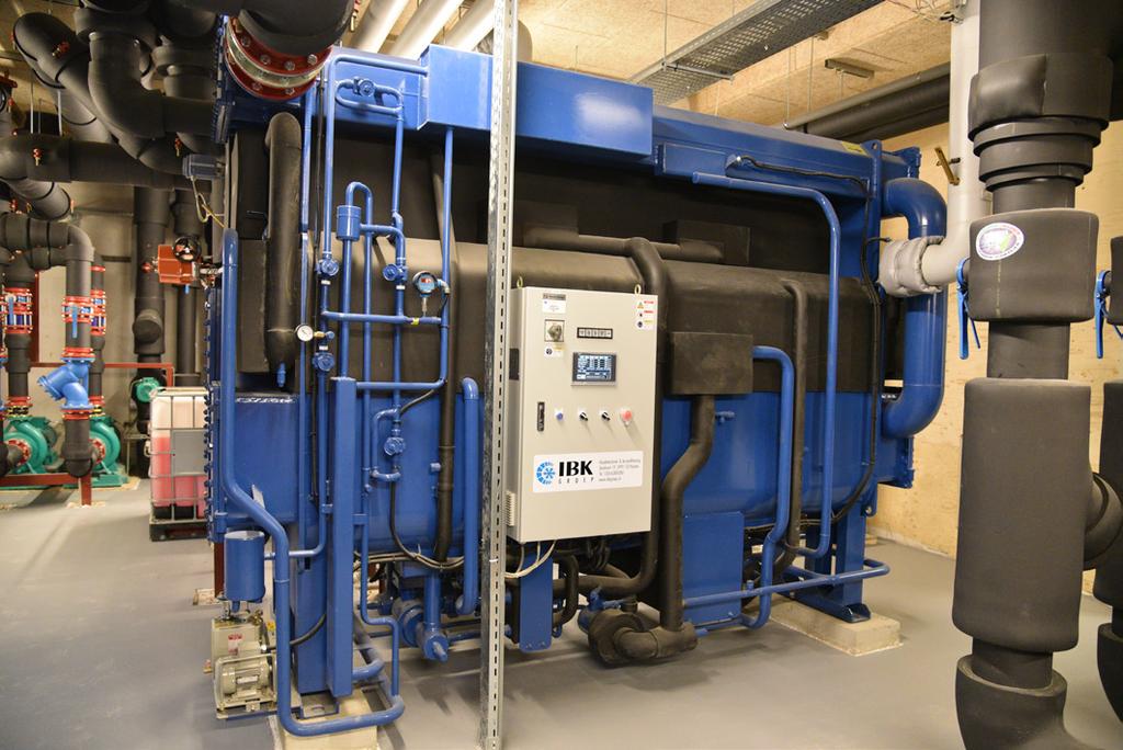
58 Installation Records 56 Single Effect Double Lift water Driven Type 2AB470, 2AB420, Total 2023 usrt Location : Korea Single Effect Double Lift water Driven Type 2AB470, Total 910 usrt Location : Korea Single Effect Double Lift water Driven Type 2AB135, Total 260 usrt Location : Korea Single Single Effect Effect Double Lift waterdriven DrivenType Type IBK HWAR-L300H 2AB75, 75 usrt Location Location : Korea The Netherlands Single Effect Driven Type HWAR-L110, 110 usrt Location : U.S.A. Single Effect Double Lift water Driven Type 2AB155, 156 usrt Location : Germany Double Effect Direct Fired Type 28 units of DWH210, 210 usrt Location : Iran Single Effect Double Lift Heat Exchanger for Fuel Cell Driven Type IBK 2ABH180 HEX920, Capacity 400 The Netherlands Location : U.S.A.

 Location : Korea")
")


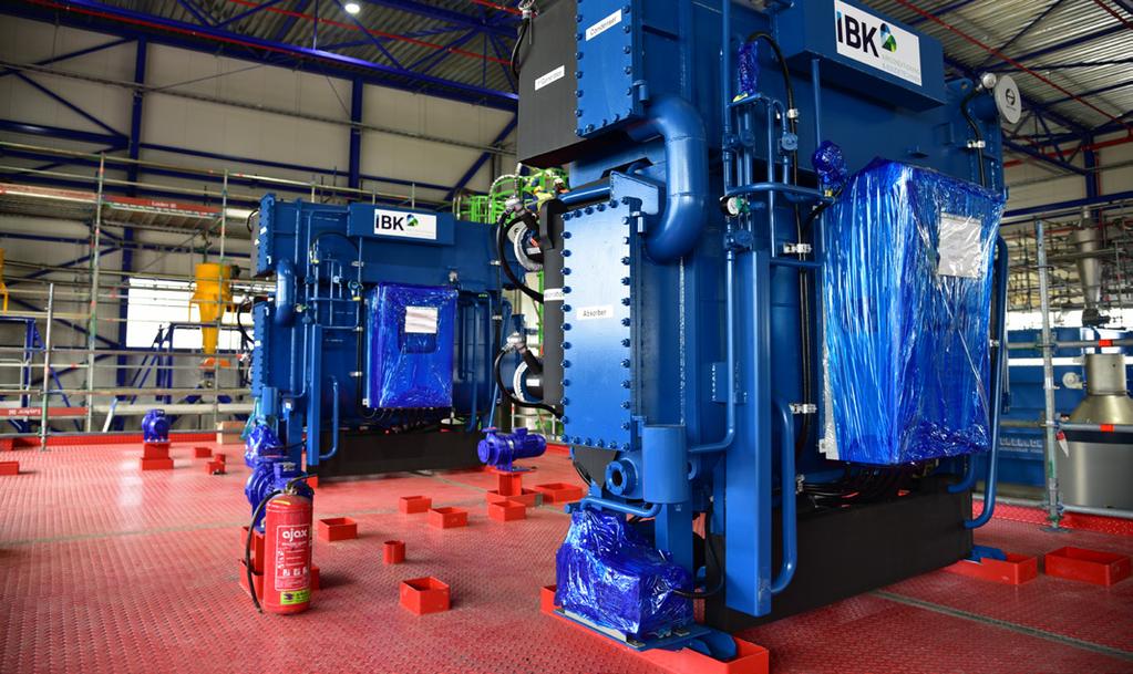
59 WORLD ENERGY Absorption Chiller Heat Pump Single Effect Steam Fired Absorption Chiller S1300, S560, L750, Total 7,800 usrt (Explotion Protection) Location : Korea Single Effect Condenser for MVR Evaporating (Mecanical VaporType Recompression System) Driven Steam Generating IBK HWAR-L 135 HHCapacity 5 ton/h Location :: Belgium Korea Location Single Single Effect Effect Steam Fired Absorption DrivenChiller Type S500, 500 usrt IBK HWAR-L180H (Explotion Protection) Location : The Netherlands Location : Korea Single Effect Double Lift water Driven Type 2AB, 240, 220 usrt Location : Korea Single Effect Driven Type HWAR-L1125, 1422 usrt (Explotion Protection) Location : Korea Single Effect Double Lift water Driven Type 2AB975, 2AB240, Total 1,036 usrt Location : Taiwan Single Effect Effect Double Lift Single waterdriven DrivenType Type 2IBK units of 2AB825, 995 usrt HWAR-L90HH Location Russia Location :: The Netherlands Single Effect Double Lift water Driven Type 2AB240, 240 usrt Location : Korea 57