chapter-3- treatment processes
|
|
|
- Griselda Horn
- 5 years ago
- Views:
Transcription
1 chapter-3- Prof. Dr. Samir Afifi Conventional wastewater Conventional wastewater treatment processes
2 Main goals of WW Treatment 1. Prevention of pollution to: p Ground water Soil marine life (aquatic life) Water bodies air
3 cont== Main goals 2. Protection of the public health 3. Solving asocial problems caused by the acumen of wastewater 4. Saving of water for reuse purpose such as: Agriculture Recharge Industrial recycle
4 Technical goals of wastewater 1. Separation of solids from liquid 2. Solid stabilization 3. Proper reuse and or disposal of liquid and solids 4. Destroy pathogenic microorganism


5 How to a chive the technical goals? How to a chive the technical Goals?
6 How to achieve the technical goals? Preliminary treatment Primary treatment Secondary treatment Physical- chemical treatment Advanced wastewater treatment Des-infection Effluent discharge
7 Municipal Wastewater Treatment Systems Pretreatment removes materials that can cause operational problems, equalization optional Primary treatment remove ~60% of solids and ~35% ofbod Secondary treatment remove ~85% of BOD and solids Advanced treatment varies: 95+ % of BOD and solids, N, P
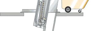
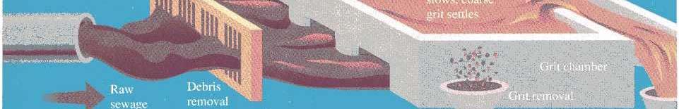
8 Preliminary treatment Remove solids by screening and settling The sewage is passed through h a screen to remove large pieces of debris (e.g. sticks, stones, rags, and plastic bags). Next, the sewage enters a grit chamber, where the water flow is slowed just enough to allow coarse sand and gravel to settle out on the bottom.
9 Preliminary treatment Screening: Manual bar screen Mechanical bar screen comminutors
10 Aim To remove floating materials To prevent damage to mechanical equipment such as pumps& aerators To prevent blockage of pipes
11 Channel width ( W ): mm W= (Q/VD) * mm mm
12 Manual bar screen


13 Mechanical bar screen
14 Mechanical bar screen
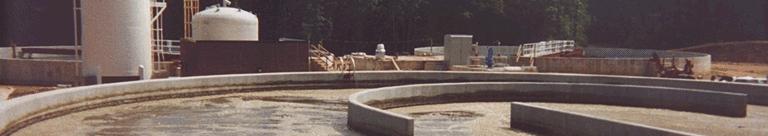
15 Grit removal Aim To prevent abrasion & wear of mechanical equipment To prevent deposition of grit in pipes / channels ((It is important to remove particle with diameter >0.2 mm and to prevent organic material sedimentation))
16 Grit Basin
17 Removal grit 1. Grit channel: Channel width = 1.5A/H Velocity of 0.03m/s 03m/s is needed for grit settling. Channel length = 20 * channel depth
18 Grit removal
19 Grit Chambers: Velocity Controlled
20 2.Aerated grit chambers
21 2.Aerated grit chambers
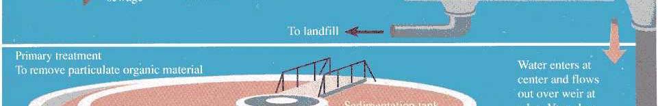
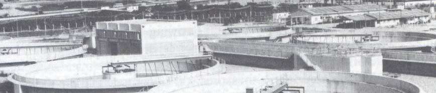
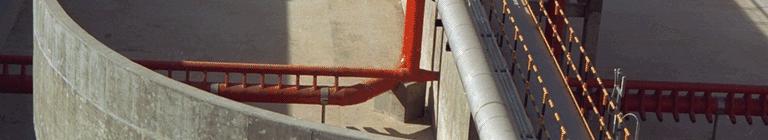
22 Primary (Treatment) sedimentation Aim: Removal of settable solids. Removal of 40% of BOD5:

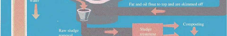
23 Primary (Treatment) sedimentation
24 Proper Primary Treatment t will reduce reactor size (construction cost) and Reduce power consumption (operational cost)
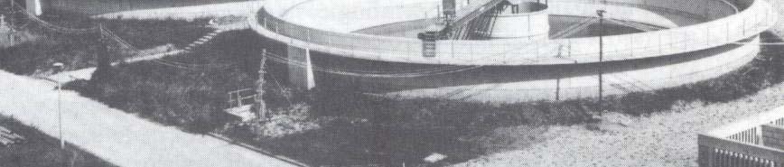
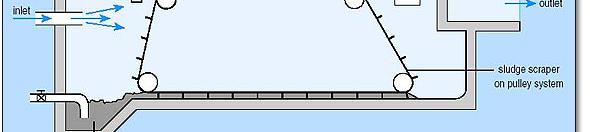
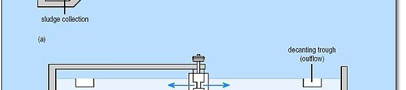
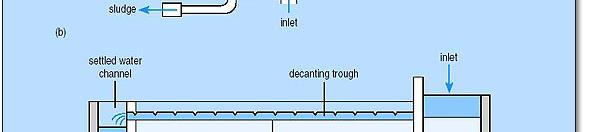
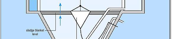
25 Sedimentation tank consist of four zones: 1. Inlet zone: reduce the sewage velocity in a minimum space
26 2. Outlet weir : Collect and withdraw the settled sewage Prevent floating material to pass over outlet weir.
27 3. Settlement zone: Area for settling Should free from: Short-circuiting Stagnant areas
28 4.Storage, collection and withdraw of sediment solids (desludging): Manual mechanical
29 Primary Settling
30 ST type 1. Horizontal flow tanks: Rectangular Length / Breadth ratio 4:1
31 Horizontal flow tanks
32 ST type 2. Radial flow tanks: circular with slope down floor. Inlet of the center and flows up and out Outlet is around the tank.
33 2. Radial flow tanks:
34 ST type 3. Upward-flow tanks: Circular or square. Inlet at tank center and flow initially downwards. Outlet is around the tank.


35 Upward-flow tanks

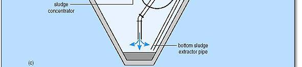
36 Typical sedimentation tanks: (a) rectangular horizontal flow tank (b) circular, radial- flow tank ( )h b tt d (c) hopper-bottomed, upward flow tank
37 Primary Settling Tank Design Size rectangular: 3-24 m wide x m long circular: 3-90 m diameter Detention time: hours Overflow rate: m 3 /m 2 day Typical removal efficiencies solids: 50-60% BOD 5 : 30-35% 5
38 Secondary Treatment Secondary Treatment
39 Secondary Treatment The main Aim of Conventional Secondary Treatment t (Biological i l Unit) is to: Reduce the Biological Oxygen Demand (BOD) through Aerobic Oxidation.
40 The process needs: organisms o s s oxygen

41 How is this accomplished? Create a very rich environment for growth of a diverse microbial community
42 Secondary Treatment Provide BOD removal beyond what is achieved in primary treatment removal of soluble BOD additional removal of suspended solids Basic approach is to use aerobic biological degradation: organic carbon + O 2 CO 2 Objective is to allow the BOD to be exerted in the treatment plant rather than in the stream
43 Basic Ingredients High density of microorganisms (keep organisms in system) Good contact between organisms and wastes (provide mixing) Provide high levels of oxygen (aeration) Favorable temperature, ph, nutrients (design and operation) No toxic chemicals present (control industrial i inputs)


44 Process Classification based on form of microbial population: fixed film processes (Microorganisms i are attached) dispersed growth processes (Microorganisms are immobilized)
45 Dispersed growth vs Fixed Growth Dispersed Growth suspended organisms Activated sludge Oxidation ditches/ponds Aerated lagoons, stabilization ponds Fixed Growth attached organisms Trickling filters Rotating Biological Contactors (RBCs)
46 Fixed film processes: Fixed film processes represent the oldest form of wastewater treatment system and includes :
47 cont==fixed film processes: Land application of sewage Trickling or Percolating filter Rotating Biological Contractor (RRC)
48 Trickling filter Trickling filter Bio-filter, bacteria bed or percolating filter
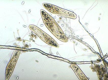
49 Trickling Filters
50 Trickling Filter Plant Layout
51 Trickling filter: Form: Rectangular or Circular Plan Inside: A permeable Media (crushed rock or blast-furnace slag of diameter mm) Depth: 3.0m to12m (depends of the filter media)
52 Trickling Filters
53 Trickling filter: Wastewater distributed ib t d mechanically over the media Effluent collected at the filter base
54 Trickling Filters
55 Treatment Process: Influent entering at the center of the bed and passing into radial distributor arms above the bed surface


56 cont== Treatment Process A microbial film develops over the surface of the media and this is responsible for removal of BOD during passage of sewage through the bed.


57 cont== Treatment Process medium aerobic O 2 CO 2 anaerobic
58 cont== Treatment Process The distribution of air through a filter occurs by circulation through h void spaces in the filter media.
59 cont== Treatment Process Filtration, in the traditional sense of straining out of large particles, does not occur and the process is solely a biological one
60 The efficiency of the system depends upon: - Distribution of settled sewage over the surface of the filter - Circulation of air throughout the filter media
61 Factors Effected Filters Loading Rates: 1. Effluent quality required 2. Media employed 3. Type of wastewater ater (Influent quality)
62 PONDED Problem: Over Loading cause excessive growth of the slime layer resulting in the voids between the media and it becoming blocked.
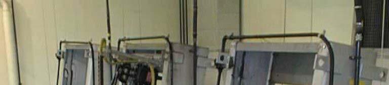
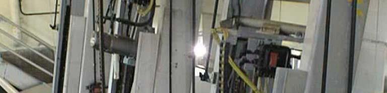
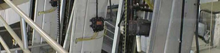
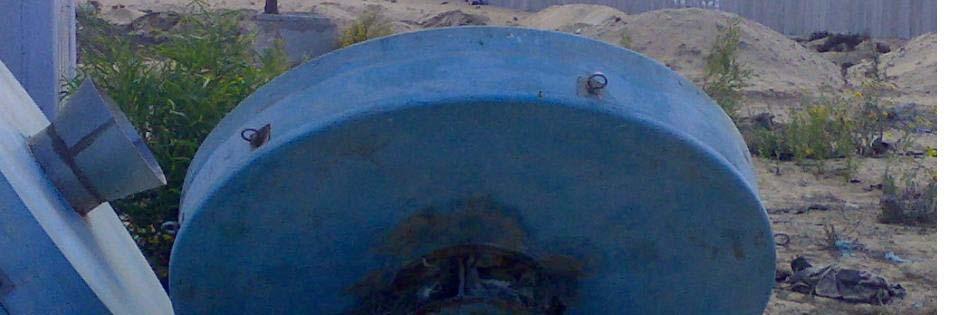
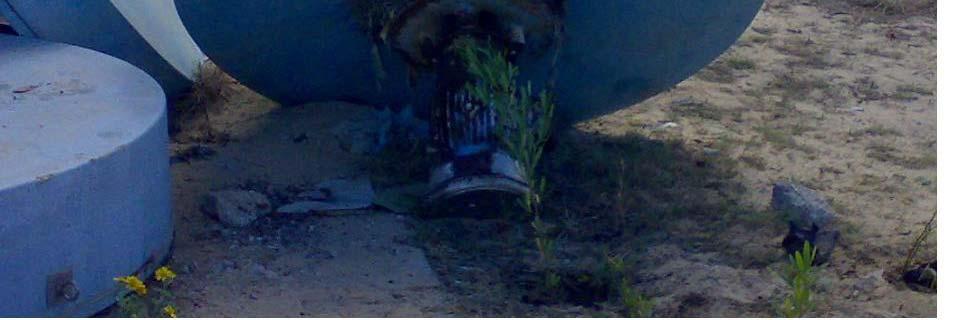
63 PONDED Problem: This prevents sewage percolating through the filter and thus it collects on the surface of the media Ponded Cause
64
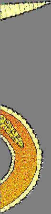
65 Sloughing off : In a well operated filter there is a continual cycle of film growth followedbydeathand death and detachment from the media. This is known as Sloughing Off.
66 Cont==Sloughing off : The resultant sludge is carried away with the filter effluent. Periodic sloughing off the slime layer is a feature of filter operation (change of seasons). During this period treatment will be severely reduced.
67 Trickling Filters Not a true filtering or sieving process Material only provides surface on which bacteria to grow Can use plastic media lighter - can get deeper beds (up to 12 m) reduced space requirement larger surface area for growth greater void ratios (better air flow) less prone to plugging by accumulating slime
68 Advantage of trickling filters: Simple technique to design and operate Have very low running costs Tolerate shock and toxic loads (short contact time)
69 Disadvantages: Land requirements high Provide a limited treatment efficiency Associated with odorous and fly nuisance (In hot countries)
70 Rotating biological contactor (RBC) (Biodisc): A rotating disc (bed) has attached bacteria The disc immersed in awastewater tank

71 Rotating Biological Contactors
72 Rotating Biological Contactors Called RBCs Consists of series of closely spaced discs mounted on a horizontal shaft and rotated while ~40% of each disc is submerged in wastewater Discs: light-weight plastic Slime is 1-3 mm in thickness on disc
73 Rotating Biological Contactors Primary Settling Sludge Treatment Secondary Settling Sludge Treatment
74 Cont==Rotating biological contactor (RBC),(Biodisc): Rotation of disk will permitting the aeration as disc expose to the atmosphere
75 Cont==Rotating biological contactor (RBC),(Biodisc): A microbial community will be developed at the disk ( from of biofilm = 3mm ) which is responsible for BOD removal
76 Rotating biological contactor (RBC), (Biodisc) Aeration Film mixes with wastewater Shearing of excess microorganisms Attached microorganisms pick up organics
77 Rotating Biological Contactors
78 Advantages: Ease to operate Low land requirement Application in rural areas Can be marketed as package Reduced power and maintenance cost Elimination of pounding and clogging
79 Disadvantages: New process Breaking and craking of discs Shaft bearing failure Rain and wind protection faultily

80 Rotating Biological Contactors
81 Dispersed Growth Processes Activated Sludge Process: The process is a suspended growth system comprising a mass of microorganisms constantly supplied with organic matter and oxygen.
82 Cont==Activated Sludge Process: The microorganisms grow in flocs, and dthese flocs are responsible for the transformation of the organic material into new bacteria, carbon dioxide and water.
83 Cont==Activated Sludge Process: Process in which a mixture of wastewater t and microorganisms i (biological sludge) is agitated and aerated Leads to oxidation of dissolved organics After oxidation, separate sludge from wastewater
84 Activated Sludge w/w Return Activated Sludge (RAS) Mixed Liquor Air Waste Activated Sludge (WAS) Secondary clarifier Treated w/w Discharge to River or Land Application
85 Dispersed Growth Processes Activated Sludge Process:
86 Dispersed Growth Processes Activated Sludge Process:

87 Activated Sludge Process


88 Actieved Sludge Process Organic Mater (BOD) + Oxygen + Microorganism Growth (Flocs)


89 Sludge floc aerobic anaerobic
90 Cont==Activated Sludge Process 2.Flocs washing out to the secondary sedimentation ti tank 3.Settling of flocs (SLUDGE)

 5.")
91 Cont==Activated Sludge Process 4.A fraction of settled sludge recycled back to the aeration tank (Returned Sludge) 5.Remainder sludge will be wasted
92 Activated Sludge w/w Return Activated Sludge (RAS) Mixed Liquor Air Waste Activated Sludge (WAS) Secondary clarifier Treated w/w Discharge to River or Land Application
93 Activated Sludge Process
94 Sludge Age The average time, which A microorganism (fraction of the solids, which are wasted) will spend in the reactor is known sludge age
95 Sludge Age and is defined as: Sludge age (d) = Total solids in reactor (Kg) Total solids wasted (Kg/d)
96 Variation principals of activated sludge process 1. The method of oxygen supply 2. Aeration tank configuration 3. Loading rate
97 Methods of oxygen supply for activated sludge: 1. Mechanical surface aeration. 2. Diffused air aeration.
98 Methods of oxygen supply for activated sludge: Diffused air aeration. Mechanical surface aeration.
99 Mechanical surface aeration: 1. Transfer O2 from atmosphere to the MIXED LIQUOR by agitation ti of the liquid surface
100 cont==mechanical surface aeration: 2. Agitation helps to keep the sludge (flocs) in suspension and prevents it settling: Vertical A Horizontal A
101 Cont==Mechanical surface aeration: The immersion depth of the aerator is very important and affect the oxygenation capacity


102 Vertical A
103 Mechanical Aerators Fixed aerator Floating aerator Turbine aerator 103
104 Diffused air aeration: 1. Located at the floor of the reactor and release air stream into mixed liquor in form of bubbles As bubbles rise to tank surface 2. As bubbles rise to tank surface, this will keep the mixed liquor solids in suspension form
105 Diffused air aeration: Ceramic Disc Air Diffuser
106 Diffusers 106
107 Type of air diffusers
108 1.Fine bubble diffused air: Tiles made of ceramic Bubbles diameter up to 2mm Provide large air/liquid interface with high oxygen transfer efficiency


109 Blockage problem attached biomass particles in air
110 2. Coarse bubble diffused air Bubbles diameter in range 3-5 mm Reduced d oxygen transfer
111 Loading rate The parameter describe the rate of applying of sewage in the AS reactor 1. Volumetric loading 2. Organic loading 3. Food: microorganism i ratio (f/mratio) 4. Floc loading
112 1.Volumetric loading: Determined the time,which the sewage will undergo aeration in reactor
113 Retention Time (d) [Hydraulic RT] = Reactor volume (m3)/total daily flow (m3/d) In cause of absence of sludge Recycle RT= sludge age Contact time (6-10)hs Aeration Tank magnitude
114 2.Organic loading: The amount of organic (BOD) applied per The amount of organic (BOD) applied per unit volume of aeration tank
115 2.Organic loading: Organic Loading (Kg BOD/m3.d)= { influent flow (m3/d) * BOD (kg/m3)} { influent flow (m3/d) BOD (kg/m3)} Reactor volume(m3)
116 3.Food-Microorganism Ratio (F/M- Ratio): Sludge loading F/M-Ratio= BOD of sewage (Kg/m3) * influent flow (m3/d) Reactor volume (m3) * Reactor Sludge (Kg/m3)
117 F/M Parameter Low F/M (low rate of wasting) starved organisms more complete degradation larger, more costly aeration tanks more O 2 required higher power costs (to supply O 2 ) less sludge to handle High F/M (high rate of wasting) organisms are saturated with food low treatment efficiency
118 4.Floc Loading: Give an indication about BOD concentration available to sludge microorganism at a given time
119 Floc loading (kg BOD/kg MLSS)= Mass of BOD at time of mixing Mass of MLSS at time of mixing Used where sludge settlement t in secondary sedimentation tank is poor FL >100 kg BOD/ kg MLSS results improvement in sludge settling
120 Effluent of loading rate on plant performance: BOD loading in influent will have the following effluent Effluent Quality sludge settling properties Efficiency of plant performance
121 1/ = Yq - ka :Sludge age Y: Sludge Yield (kg/kg BOD) Q: organic loading rate (kg BOD/kg MLSS)
122 Aeration tank configuration: The configuration of selected Activated t Sludge reactors (aeration Tank) will have effects on many aspects of plant performance and economy y( (running and construction costs)
123 Secondary Treatment Aeration Tank "Reactor"
124 Batch Reactor ( BR): Activated sludge known as the fill and draw process: A reactor filled with settled sewage Aeration for sufficient time (generally 8-12 hours) Settling the reactor contents
125 Cont==Batch Reactor ( BR): Discharge the treated supernatant to a watercourse Portion of the settled sludge will be wasted The process repeated again
126 Cont==Batch Reactor ( BR): The process (BR) Lost fervor because of the amount of operator control required
127 Sequencing Batch Reactor (SBR): A recent modification of BR process know as a sequencing batch reactor (SBR) is gaining increased popularity.
128 Cont==Sequencing Batch Reactor (SBR): SBR allows different removal processes to be performed in the same reactor : Carbonaceous oxidation Nitrification, Denitrification Phosphate removal
129 Sequencing Batch Reactor (SBR) Suspended growth system Completely mixed mode; batch mode with discontinuous flow Typical F/M = 0.05~0.1 (comparable to an extended aeration type process) Influent Fill React Settle 4 5 Effluent Draw Idle
130 Causes suitable to apply RBC technology: Highly variable hydraulic and organic loads Small communities Vacation resorts and institutional facilities
131 Complete Mix Reactors (CMR): 1. Rapidly distributed of settled sewage and return activated t sludge 2. MLSS, BOD and O2 concentration should have the same values in any point in the reactor
132 Cont==Complete Mix Reactors (CMR): Advantage: Large dilution of influent provides a buffer against any toxic substances Uniform distribution of load ensure an efficient use of aerators
133 Cont==Complete Mix Reactors (CMR): Disadvantages: Short-circuiting, leads to not adequate treatment. Low floc loading, leads to sludge settlement problems.
134 Completely-Mixed Activated Sludge (CMAS) Objective is to mix aeration basin completely. l CMAS is inflexible (one basin); also CMAS systems tend to bulk more than conventional systems at low F/M; CMAS is useful to disperse toxic or shock loads and even out DO demand for high strength wastewater. Raw or settled wastewater Aeration tank Final clarifier Effluent Return activated sludge (RAS) WAS
135 Oxidation Ditches: Originally designed as: Inexpensive treatment system for small rural communities Shallow (1m) continuous oval ditches Excavated directly or with simple lining for certain soil types
136 Cont==Oxidation Ditches: Operated at very low loading rates No need for primary sedimentation A horizontal paddle aerator provided mixing and aeration
137 Cont==Oxidation Ditches: Mixed liquor keep in circulation around the ditch After a suitable period of aeration, the aerator turned off and the ditch served as secondary sedimentation tank
138 Cont==Oxidation Ditches: Low loading rates sludge ages result: 1. Low sludge production (as result of endogenous respiration) 2. Effluent completely nitrified
139 Oxidation Ditches:
140 Low Rate Activated Sludge Oxidation Ditch Low rate, suspended growth system Can be operated intermittently or continuously. Continuous operation requires secondary clarifiers. Loading rates = 10~15 lb BOD 5 /1000 ft 3 day Useful for small communities; but large space required. RAS WAS Rotor Influent Oxidation ditch Final clarifier Effluent
141 Modified oxidation ditches: Represent high wastewater treatment technology Separation secondary settlement tanks The ditch is invariably constructed using concrete
142 Cont==Modified oxidation ditches: Vertical shaft cone aerators employed Carrousel process types for large populations


143 Oxidation Ditch
144 Plug-Flow Reactors: 1. Tanks with a high length to breadth ratio 2. The reactor consists of a number of tanks or pockets in series, each equipped with its own aerator (pocket behaves a complete mix reactor)
145 Cont==Plug-Flow Reactors: 3) Settled sewage and return sludge introduced at one end and remove at the other 4) Samples along the tank show a gradient of decreasing BOD, increasing MLSS and decreasing oxygen demand
146 Cont==Plug-Flow Reactors: 5) As load and oxygen demand not evenly distributed ib t d along, step aeration is apply ) This modification of air supply 6) This modification of air supply matches the BOD demand and is utilized more efficiently
147 Plug-Flow RAS and sewage are fed at one and the same point in aeration basin. The basin configuration will determine degree of mixing. Raw wastewater Final clarifier Effluent Primary sedimentation tank (optional) Sludge Return activated sludge (RAS) Waste activated sludge (WAS)
148 Cont==Plug-Flow Reactors: 7) Advantages : reducing total plant running costs up to 50% 8) Floc loading problem of sludge settlement traditionally reduced
149 Step Feeding: 1) The technique is employed only on plug-flow reactors with the aim of : Distributing the load more evenly Avoiding oxygen deficiency at the inlet
150 Cont==Step Feeding: 2) All return sludge recycled to the reactor inlet 3) The flow of the incoming settled sewage spilt and fed to a number of pockets

151 Cont==Step Feeding: 4) If too many increments of feed are employed, reactor will resemble in CMR
152 Step Aeration Tank size for aeration may be reduced to about the half the size of CAS. More efficient use of oxygen. Can have some part of aeration basin devoted to RAS reaeration alone. Raw wastewater Primary sedimentation ti tank Final clarifier Effluent Sludge RAS WAS
153 Modifications of conventional sludge process: Variations are possible, based on : Differing reactor configuration modes of aeration Modification haves generally a specific function
154 Cont==Modifications tmodifications of conventional C sludge process: Reduce construction and operation costs Modification to existing conventional plants

155 Completely new plant {Understanding the philosophy behind the modification is important}


156 (A/B) process: The absorption-bio-oxidation (A/B) process
157 Cont==(A/B) process: Two stage process in series The aim to maximize the production of sludge in two reactor


158 Cont==(A/B) process: Oxygen is required for oxidative process which produced energy and carbon dioxide
159 Cont==(A/B) process: The process operates without primary sedimentation A separation of the first-stage sludge from that of the second stage
160 Cont==(A/B) process: Two secondary clarifiers are required A The first has a very high sludge A. The first has a very high sludge loading rate:
161 Cont==(A/B) process: 3-7 kg BOD/kg MLSS d. (operating in facultative ti anaerobic mode ) 50% ofthe influent BOD is achieved
162 Cont==(A/B) process: Reducing energy required to remove 1 kg of BOD from 0.3 kwh to 0.15 kwh. Exploiting the gut microorganism in raw sewage.
163 Cont==(A/B) process: B. The B stage completes the oxidation of the sewage : Loading rate 0.5kg BOD/kg MLSS g g g d.
164 Cont==(A/B) process: Operates aerobically with high solids retention time, with nitrification of ammonia Efflent ammonia concentration 5-10mg/1.
165 Cont==(A/B) process: A/B process can have a loading rate 50% more than conventional single stage activated sludge plant with the same effluent quality
166 Contact stabilization : Process to solve the sludge settlement in CMR The process provides zone with The process provides zone with high floc loading in a small tank
167 Cont==Contact stabilization : Screened sewage + return sludge 30 min in AT ( contact zone)
168 Cont==Contact stabilization : Settling effluent to wc sludge transfer to stabilization zone (aeration up to 12 hours )
169 Cont==Contact stabilization : Sludge returned to contact zone Sludge absorbed BOD to floc
170 Cont==Contact stabilization :
171 Cont==Contact stabilization : Advantages : large reduction of AT Sludge for a package plant for small communities
172 The absorption-bio-oxidation oxidation (A/B) process: The aim is to maximize sludge production Has two stage AS The process operates without primary sedimentation
173 tthe Cont==The absorption-bio-oxidation (A/B) process: Two secondary clarifiers are required First stage (A-stage): Has very high sludge loading rate (3-7kg BOD/kg MLSS/d) Facultative anaerobic
174 tthe Cont==The absorption-bio-oxidation (A/B) process: Treatment efficiency is low Rabid BOD removed (50%) Energy required low (0.15kwh/1kg BOD) BOD removed mechanism is absorption
175 tthe Cont==The absorption-bio-oxidation (A/B) process: B-stage: Has low sludge loading (0.3kgBOD/kg MLSS) Aerobic with high solids R.T Nitrification is occur
176 tthe Cont==The absorption-bio-oxidation (A/B) process: This system save in aeration cost Sludge (organic mater ) used CH4 produced (anaerobic Digestion)


177
178 True or false: 1. The aim of primary treatment To prevent blockage of pipes 2. The aim of Grit removal is to prevent organic material sedimentation 3. 40% of BOD5 remove in primary sedimentation
179 True or false: 4. Settlement zone Should free from Short-circuiting 5. Fixed film processes represent the oldest form of wastewater t treatment t t system 6. trickling filters Simple technique to design,operate and high running costs
180 True or false: 7. RBC elimination of pounding and clogging 8. The average time, which a microorganism will spend in the reactor is known sludge age 9. Coarse bubble diffused air Reduced oxygen transfer
181 True or false: 10. CMR rapidly distributed of settled sewage and return activated sludge
182