Nuts and Bolts Design, Construction and Operation of LFGTE Projects
|
|
|
- Dorcas Sharp
- 5 years ago
- Views:
Transcription


1 Nuts and Bolts Design, Construction and Operation of LFGTE Projects Mississippi LFG Energy Workshop U. S. EPA Landfill Methane Outreach Program April 25, 2002
2 Regulatory Framework
3 LFG Regulatory Framework RCRA Subtitle D NSPS Title V Other Clean Air Act Provisions State Rules Local Air District Rules
4 Landfills Applicable under NSPS MSW Landfills Received Waste on or after 11/08/87 Waste Design Capacity >= 2.5 million Mg Annual NMOC Emissions >= 50 Mg
5 Title V Permits Major Sources require permit. Facilities subject to NSPS/EG require permit (despite being a minor source based on estimated emissions). Permit Components: Emissions inventory Review of applicable regulations Application Certification of compliance Monitoring, reporting, and record keeping
6 Design
7 Landfill Gas Collection Systems Landfill gas extraction wells Horizontal Vertical Landfill gas blower stations Landfill gas condensate management Landfill gas safety issues
8 Vertical Extraction Wells Design Criteria Extraction Wells Layout Spacing Borehole Depth Borehole Diameter Drilling Method Presence of Water Dual Extraction with Leachate Pipe Material Pipe Depth Well Screen Backfill
9 Vertical Extraction Wells Design Criteria (cont.) Well Head / Lateral Material Above vs. Below Grade Cover Valve Access for Monitoring
10 Vertical Extraction Wells Design Criteria (cont.) Header Lines General Layout Depth Material Bedding / Backfill Slope Diameter Protection
11 Vertical Extraction Wells Design Criteria (cont.) Condensate Management Vacuum Trap / Seal Re-injection Collection Number / Location Construction Access Maintenance
12 Horizontal Collectors Design Criteria Layout Bedding / Backfill Spacing Temporary / Depth Sacrificial Material / Permanent / final Construction Cap Condensate Management
13
14
15
16 LFG Extraction Well
17 Horizontal Collector
18 Condensate Sump

19 Condensate Trap
20 Aboveground LFG Collection Pipes
21 Aboveground LFG Pipe Support Detail
22 Underground LFG Pipe Trench Detail
23 LFG Header Profile
24 Blower Station
25 DISPOSAL AND UTILIZATION
26 Other Blower /Flare Design Elements Secured Area Aboveground Piping Valving Condensate Management Monitoring System / Access
27 Other Blower /Flare Design Elements (cont.) Security / Alarm / Control Systems Flame Arrestors Explosion Proofing Structure
28 LFG Blower Systems Design Elements Centrifugal Exhauster Explosion Proofed Condensate Management Electric Supply Electric Motor Number / Layout Material
29 LFG Treatment / Disposal Design Alternatives Atmospheric Vent GAC (Carbon) Treatment Open / Candle Flare Enclosed / Ground Flare Incinerator End Use
30
31
32 Energy Recovery Electric generation Medium Btu High Btu Vehicle fuel Carbon dioxide recovery Fuel cells Chemical feedstocks
33 CONSTRUCTION


34 Boring activity for installation of LFG well Perforated and solid piping for LFG wells

35 Installation of LFG header piping LFG wellhead near completion


36 Completed LFG wellhead Installation of LFG header piping

37 HDPE header pipe and condensate piping in trench LFG lateral connection to header pipe


38 LFG header piping and isolation valves Trench compaction and backfill


39 Geosynthetic liner over trench LFG header roadway crossings


40 Condensate sump Condensate sump with air regulator

41 Condensate sump Candle flare


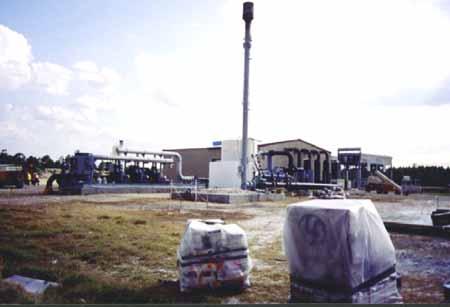
42 Flare and blower station Dual flame arrestors


43 Construction of ground flare Ground flare condensate knock-out and instrumentation

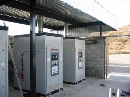
44 Typical blower shelter Microturbine Facility

45 Microturbine Facility Blower and Compressor Skid

46 Direct Use in a Boiler

47 Reciprocating Engine Generators Using LFG
48 MONITORING, OPERATIONS, AND MAINTENANCE
49 What to Expect Full-time or part-time personnel dependent on complexity of system. Coordination of the LFG developers monitoring needs with that of regulatory needs. Maintenance of wellfield Maintenance of energy recovery unit
50 Surface Emission Monitoring Ensure Gas System Performance with Surface Emissions < 500 ppm CH4 Use Portable CH4 Device : OVA, FID, SEM Walk over LF Surface in Serpentine Fashion, Lines Spaced 30 m on Center Test 5 to 10 cm Above LF Surface U.S. EPA Method 21 as Modified Quarterly monitoring
51 Title V Suggestions Carefully read draft permit. Make sure PTE allows for growth. See big picture - recognize potential secondary impacts to permit conditions. Evaluate all facility modifications w/r to impact on Title V permit. Take enforcement seriously. Budget for Title V annual fees.