Pump Performance Curves and Matching a Pump to a Piping System
|
|
|
- Christiana McKinney
- 5 years ago
- Views:
Transcription
1 Pump Performance Curves and Matching a Pump to a Piping System
2 Fundamental Parameters Some fundamental parameters are used to analyze the performance of a pump Mass flow rate (Volumetric Flow rate in case of compressible fluids) In the turbomachinery industry, volume flow rate is called capacity and is simply mass flow rate divided by fluid density Net head H The dimension of net head is length, and it is often listed as an equivalent column height of water, even for a pump that is not pumping water. Special case with D out = D in and Z out = Z in we will have
3 By dimensional reasoning, we must multiply the net head from previous equation by mass flow rate and gravitational acceleration to obtain dimensions of power. Thus, In pump terminology, the external power supplied to the pump is called the brake horsepower, which we abbreviate as bhp. For the typical case of a rotating shaft supplying the brake horsepower, We define pump efficiency as the ratio of useful power to supplied power,
4 Performance Curve Free Delivery The maximum volume flow rate through a pump occurs when its net head is zero, H = 0; this flow rate is called the pump s free delivery. The free delivery condition is achieved when there is no flow restriction at the pump inlet or outlet in other words when there is no load on the pump. Volumetric flow rate is large Head is zero pump s efficiency is zero because the pump is doing no useful work, as is clear from previous equation Shutoff head The net head that occurs when the volume flow rate is zero, V = 0, and is achieved when the outlet port of the pump is blocked off. H is large Volumetric flow rate is zero pump s efficiency is again zero, because the pump is doing no useful work. Best efficiency point (BEP) The pump s efficiency reaches its maximum value somewhere between the shutoff condition and the free delivery condition; this operating point of maximum efficiency is appropriately called the best efficiency point (BEP)

5 The Plots of Actual Head, Total power consumption, and efficiency versus volumetric flowrate are called Characteristic curves The steady operating point of a piping system is established at the volume flow rate where H required = H available.
6 For a given piping system with its major and minor losses, elevation changes, etc., the required net head increases with volume flow rate. On the other hand, the available net head of most pumps decreases with flow rate, as in Figure, at least over the majority of its recommended operating range. Hence, the system curve and the pump performance curve intersect as sketched in following Figure and this establishes the operating point. If efficiency is of major concern, the pump should be carefully selected I. A new pump should be designed such that theoperating point is as close to the BEP point as possible II. may be possible to change the shaft rotation speed so that an existing pump can operate much closer to its design point (best efficiency point).
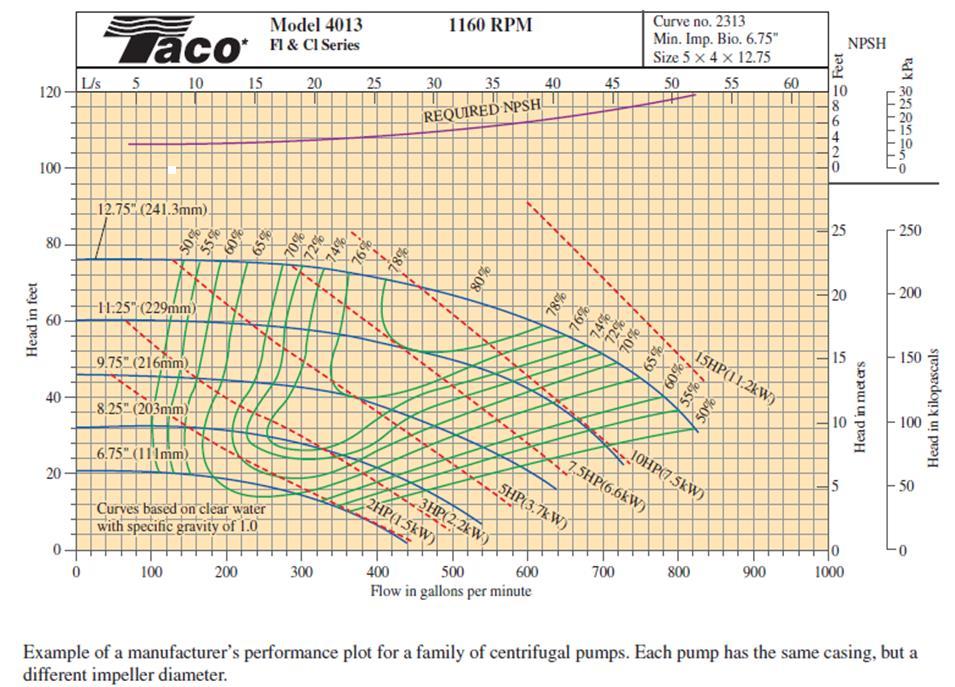
7 Pump Manufacturer Performance Curves It is common practice in the pump industry to offer several choices of impeller diameter for a single pump casing. There are several reasons for this to: I. save manufacturing costs, II. enable capacity increase by simple impeller replacement, III. standardize installation mountings, IV. enable reuse of equipment for a different application.

8 combine performance curves of an entire family of pumps of different impeller diameters onto a single plot Specifically, they plot a curve of H as a function of V. for each impeller diameter in the same way as in Figure. but create contour lines of constant efficiency, by drawing smooth curves through points that have the same value of pump efficiency for the various choices of impeller diameter.
9
10 Conclusion It is clear from the performance plot that for a given pump casing, the larger the impeller, the higher the maximum achievable efficiency. Why then would anyone buy the smaller impeller pump? To answer this question, we must recognize that the customer s application requires a certain combination of flow rate and net head. If the requirements match a particular impeller diameter, it may be more cost effective to sacrifice pump efficiency in order to satisfy these requirements.
11 Pump Cavitation and Net Positive Suction Head When pumping liquids, it is possible for the local pressure inside the pump to fall below the vapor pressure of the liquid, P v. (P v is also called the saturation pressure P sat When P, Pv, vapor-filled bubbles called cavitation bubbles appear. In other words, the liquid boils locally, typically on the suction side of the rotating impeller blades where the pressure is lowest. After the cavitation bubbles are formed, they are transported through the pump to regions where the pressure is higher, causing rapid collapse of the bubbles. It is this collapse of the bubbles that is undesirable, since it causes noise, vibration, reduced efficiency, and most importantly, damage to the impeller blades. Repeated bubble collapse near a blade surface leads to pitting or erosion of the blade and eventually catastrophic blade failure. It is useful to employ a flow parameter called net positive suction head (NPSH), defined as the difference between the pump s inlet stagnation pressure head and the vapor pressure head,

12 Pump manufacturers test their pumps for cavitation in a pump test facility by varying the volume flow rate and inlet pressure in a controlled manner. Specifically, at a given flow rate and liquid temperature, the pressure at the pump inlet is slowly lowered until cavitation occurs somewhere inside the pump. The value of NPSH is calculated using equation and is recorded at this operating condition. The process is repeated at several other flow rates, and the pump manufacturer then publishes a performance parameter called the required net positive suction head (NPSH required ), defined as the minimum NPSH necessary to avoid cavitation in the pump.
13 Pumps in Series and Parallel When faced with the need to increase volume flow rate or pressure rise by a small amount, you might consider adding an additional smaller pump in series or in parallel with the original pump. Arranging dissimilar pumps in series or in parallel may lead to problems, especially if one pump is much larger than the other. A better course of action is to increase the original pump s speed and/or input power (larger electric motor), replace the impeller with a larger one, or replace the entire pump with a larger one. Arranging dissimilar pumps in series may create problems because the volume flow rate through each pump must be the same, but the overall pressure rise is equal to the pressure rise of one pump plus that of the other. If the pumps have widely different performance curves, the smaller pump may be forced to operate beyond its free delivery flow rate, whereupon it acts like a head loss, reducing the total volume flow rate. Arranging dissimilar pumps in parallel may create problems because the overall pressure rise must be the same, but the net volume flow rate is the sum of that through each branch. If the pumps are not sized properly, the smaller pump may not be able to handle the large head imposed on it, and the flow in its branch could actually be reversed; this would inadvertently reduce the overall pressure rise. In either case, the power supplied to the smaller pump would be wasted.

14 Series Combination When operated in series, the combined net head is simply the sum of the net heads of each pump (at a given volume flow rate).
 are")
15 Parallel Combination When two or more identical (or similar) pumps are operated in parallel, their individual volume flow rates (rather than net heads) are summed
16 Affinity Laws Dimensionless groups those are useful for relating any two pumps that are both geometrically and dynamically similar. It is convenient to summarize the similarity relationships as ratios. Some authors call these relationships similarity rules, while others call them affinity laws. For any two homologous states A and B The pump affinity laws are quite useful as a design tool. In particular, suppose the performance curves of an existing pump are known, and the pump operates with reasonable efficiency and reliability. The pump manufacturer decides to design a new, larger pump for other applications, e.g., to pump a much heavier fluid or to deliver a substantially greater net head. Rather than starting from scratch, engineers often simply scale up an existing design. The pump affinity laws enable such scaling to be accomplished with a minimal amount of effort.
17 Centrifugal Pumps Centrifugal pumps and blowers can be easily identified by their snail-shaped casing, called the scroll They are used in cars the water pump in the engine, the air blower in the heater/air conditioner unit, etc. Centrifugal pumps are ubiquitous in industry as well; they are used in building ventilation systems, washing operations, cooling ponds and cooling towers, and in numerous other industrial operations in which fluids are pumped There are three types of centrifugal pump that warrant discussion, based on impeller blade geometry backward-inclined blades (most common) radial blades, forward-inclined blades.
18 Backward-inclined blades most common yield the highest efficiency of the three because fluid flows into and out of the blade passages with the least amount of turning. Sometimes the blades are airfoil shaped, yielding similar performance but even higher efficiency. The pressure rise is intermediate between the other two types of centrifugal pumps Radial blades (also called straight blades) Have the simplest geometry Produce the largest pressure rise of the three for a wide range of volume flow rates The pressure rise decreases rapidly after the point of maximum efficiency Forward-inclined blades Produce a pressure rise that is nearly constant, albeit lower than that of radial or backward-inclined blades over a wide range of volume flow rates. Forward-inclined centrifugal pumps generally have more blades, but the blades are smaller Centrifugal pumps with forward-inclined blades generally have a lower maximum efficiency than do straight-bladed pumps
.")

19 Radial and backward-inclined centrifugal pumps are preferred for applications where one needs to provide volume flow rate and pressure rise within a narrow range of values. These types of pumps are less forgiving (less robust). The performance of forward-inclined pumps is more forgiving and accommodates a wider variation, at the cost of lower efficiency and less pressure rise per unit of input power. If a pump is needed to produce large pressure rise over a wide range of volume flow rates, the forward-inclined centrifugal pump is attractive.

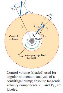
20 Velocity Distribution from Centrifugal Pumps


21 Velocity Distribution from Centrifugal Pumps (cont.)
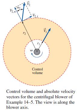
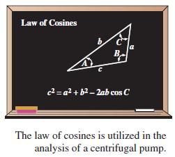
22 Velocity Distribution from Centrifugal Pumps (cont.)

23 Velocity Distribution from Centrifugal Pumps (cont.)