RMIT University. Presentation at IIT Madras
|
|
|
- Tyler Arnold
- 5 years ago
- Views:
Transcription


1 RMIT University RMIT is a global university of technology and design and Australia's largest tertiary institution. The University enjoys an international reputation for excellence in practical education and outcome-oriented research. RMIT is a leader in technology, design, global business, communication, global communities, health solutions and urban sustainable futures. RMIT has three campuses in Melbourne, Australia, and two in Vietnam. We offer programs through partners in Singapore, Hong Kong, mainland China, Malaysia, India and Europe. We enjoy research and industry partnerships on every continent. The University's student population of 74,000 includes 30,000 international students, of whom more than 17,000 are taught offshore (almost 6,000 at RMIT Vietnam). 1

2 Renewable Energy Open Lab RMIT University 2


 School")

3 Demand for fresh water and electricity: Combined Desalination and Power generation system Presenter: Abhijit Date Energy Conservation And Renewable Energy Group (Energy CARE Group) School of Aerospace Mechanical and Manufacturing Engineering abhijit.date@rmit.edu.au

4 Energy demand 4

5 Fresh water availability Glaciers and Icecaps 5

6 Land Salinity Issue In many areas around Australia the aquifer is getting salty. Picture from salt effect area in northern Victoria 6

7 Land Salinity Issue Many areas of formerly productive land are suffering from rising salinity levels around the world. Picture of a Salt lake in the northern Victoria 7
8 8
9 Desalination / Distillation methods Distillation Multi-stage flash distillation (MSF) Multiple-effect distillation (MED) Vapor-compression (VC) Membrane processes Reverse osmosis (RO) Membrane distillation (MD) Freezing desalination Single stage humidification-dehumidification (HDH) Multiple-effect humidification (MEH) Seawater greenhouse 9
 Adapted from Lubna K.")
10 Multi-stage flash distillation plants produce 85% Multiple-effect distillation (MED ME) Adapted from Lubna K. Hamdan (2008) 10


11 Reverse Osmosis Pressure Membrane Saline water Fresh water Salt 11
12 Low temperature heat engines Organic Rankine Cycle heat engines are most commonly used for power generation from low temperature heat source. Expander / Turbine m hot _ water 10kg/ Q Utilised Hot water s In (95) º C Hot water out (90) º C 2 Heat Exchanger 1 Saturated Vapour at (90) º C 2 Organic working fluid (Binary) Sub cooled Liquid 3 Pump Saturated Mixture at (35) º C Pump Condenser 3 4 Saturated or sub cooled Liquid at (35) º C Cold water Out Cold water In (30-20) º C T T kw m hot _ water cp water In exit
13 Combined Desalination and Power generation system (Direct Trilateral cycle) Vacuum tank Cooling water Vacuum Non condensable gas Condenser Electric Generator Water Vapour (35 C) Reaction Turbine Fresh Water Q Utilised Hot saline water (95 C, 3% salt) m hot _ water 10kg/ s Brine (35 C) T T kw m hot _ water cp water In exit


14 Hero's - Simple reaction steam turbine Barkers water turbine 14

15 Trilateral cycle: Two phase simple reaction turbine V a V r T h exit exit, P, v exit exit, Diverging section of the nozzle Throat of the nozzle A throat R A exit Inlet U,T shaft Hot saline water enters the turbine T, P in in m in h, v, in High velocity mixture Exit U R; V V U; T mv R; V r A W exit shaft v o. mv. m o a 2 2 R 2( h 2 2 R 2( h. mv r exit in in h h exit exit ) ) shaft a 2 2 R 2( h 2 2 T mr R 2( h h ) R shaft. in exit in h exit ) overall W Q shaft Extractable Turbine. m R nozzle. W mc 2 2 R 2( h p. shaft mc ( T p ( T in Va m 2 in T in T 2 exit ) h exit exit ) ) R 15
16 Theoretical Predictions Tin 95 C ; Texit 35 C ; m 4kg/ s; isentropic 50%; Q Supplied / utilised 1MW 16
17 Shaft Power (kw) Theoretical Predictions Tin 95 C ; Texit 35 C ; m 4kg/ s; isentropic 50%; Q Supplied / utilised 1MW Rotational Speed (rpm) 17


18 Investigation of the optimum length of diverging section of the two phase flow stationary nozzle Computational analysis Experimental analysis 18

")
19 Pressure (kpa) Investigation of the optimum length of diverging section of the two phase flow stationary nozzle 500 Ohta Nozzle B Pressure (kpa) Throat Nozzle Length (mm) 19


20 Combined Desalination and Power generation system (Stage 1: Design) Flashing tank Brine tank Custom made coil condenser 25mm tube diameter 12 branches Each branch about 10 m length Fresh water tank Total cooling capacity of about cooling water flow rate and 12C T 20

21 Stage 1: CDP system in operation Hot water supplied at 98 C, 35 C turbine outlet and 0.3kg/s inlet mass flow. Produced 400W peak electrical power at rpm and 0.03kg/s fresh water 21
22 Combined Desalination and Power generation system Stage 2: Design Vacuum vessel Vacuum Non condensable gas Flashing Tank Reaction Turbine Brine Condenser Electric generator Hot saline water (65 C +, 3% salt) Fresh Water Cooling water 22

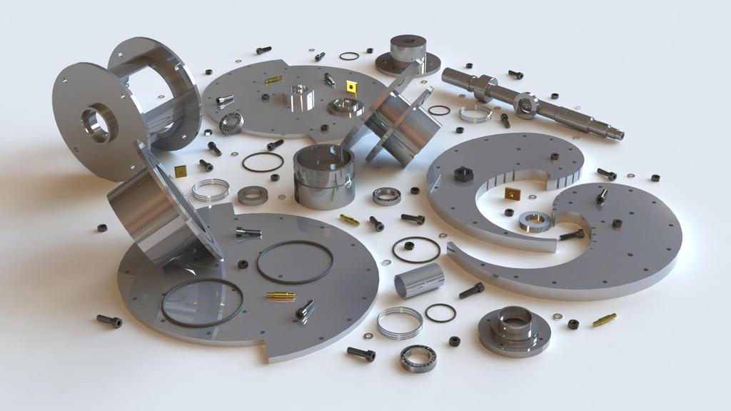
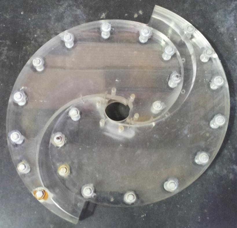
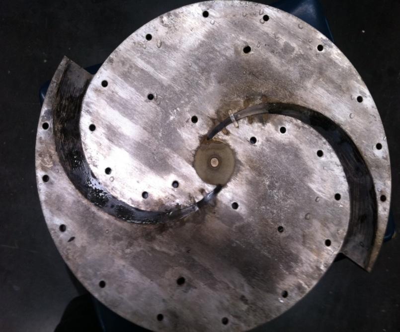
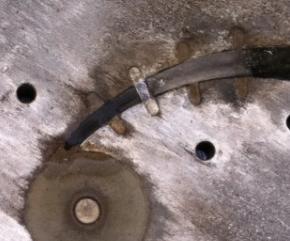
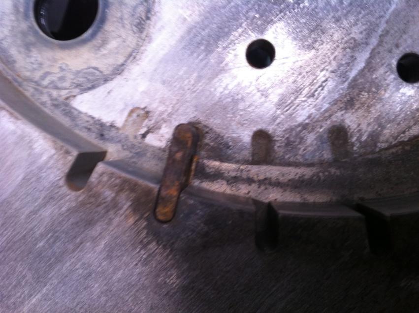
23 Combined Desalination and Power generation system Stage 2: Design 23


24 Combined Desalination and Power generation system Stage 2: Design 24

25 Combined Desalination and Power generation system Stage 2: Design 25

26 Vacuum (5kPa, Abs) Atmospheric pressure Hot saline water 26
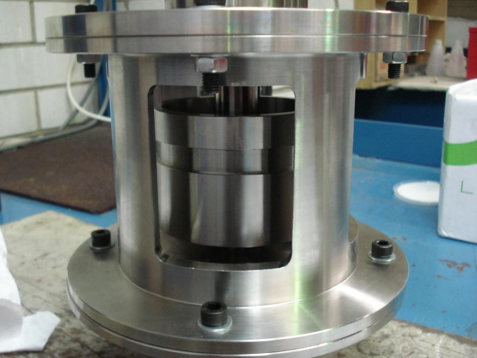
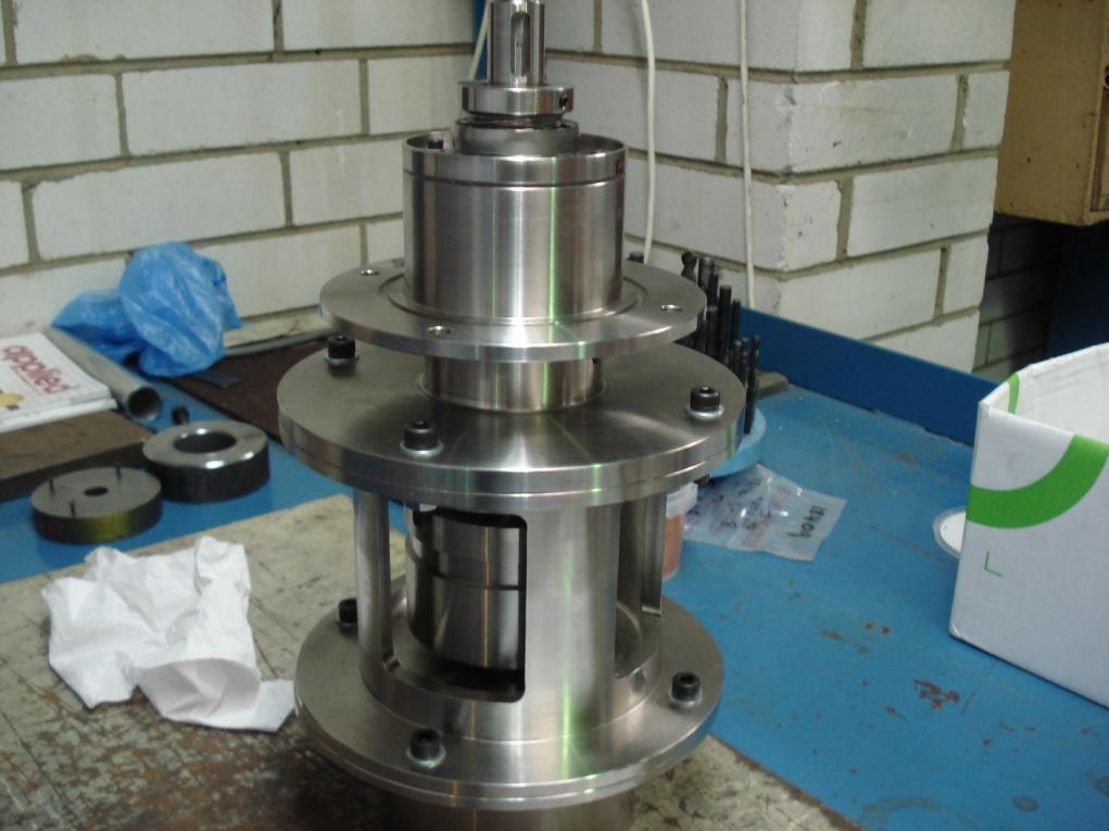
27 Rotary mechanical seal Vacuum (5kPa, Abs) Atmospheric pressure Braking pulley Hot saline water Rotary mechanical seal 27

28 Vacuum (5kPa Abs) Rotary mechanical seal Atmospheric pressure 28
29 29
30 30

31 31


32 Turbine 1 Turbine 2 32


33 33
34 Experimental technique and results T 95 C ; T 35 C ; m 0.4kg s in exit / Dynamic _ frictional _ torque _ T Shaft _ Power _ W shaft Useful o _ Mechanical _ d I dt Acceleration Power I mass _ moment _ of _ inertia T O Frictional _ power _ loss d dt Deceleration 34
35 Experimental results Tin 95 C ; Texit 35 C ; m 0.4kg/ s 35
36 Experimental results Tin 95 C ; Texit 35 C ; m 0.4kg/ s Turbine _1 Turbine _ 2 max_ isentropic max_ isentropic 9% 17% 36

37 Turbine 3: 300 mm diameter turbine with circular cross-section nozzle and throat diameter 2mm 37

38 2 u R 2 w Optimum shape of the curved nozzle at different rotational speeds with Computational minimum Fluid fluid Dynamics separation Analysis 2 2 w u 2uw cos 0 R R R u w the the is inside is of local is is is local local rotating local rotor local angle the of rotor direction centripetal centripetal radius radius tan gential relative the nozzle between rotating and of of of fluid the normal the the accleration accleration 2uw acceleration due to R dw acceleration of the dt curvature velocity rotor velocity nozzle local nozzle in coriolis fluid to of of radius relative effect streamwise motion Diverging section of the nozzle u - Local tangential velocity of rotor Centripetal acceleration Throat of the nozzle Coriolis acceleration Hot saline water enters the turbine Centripetal acceleration in relative motion High velocity mixture 38 Acceleration of fluid stream
39 Gross Shaft Power (Watts) Experimental results: 300 mm diameter turbine with circular cross-section nozzle and throat diameter 2mm Temperature ( C) or Flow rate of feed water (lit/min) Gross shaft power T3-WP Nozzle exit temperature - T3-WP Supply Temp - T3-WP Feed water flow rate Angular speed (rad/s) 39
40 Isentropic efficiency (%) Shaft Power (W) Experimental results 300 mm diamter turbine with circular cross-section nozzle and throat diameter 2mm 60% Isentropic efficiency Shaft Power 1,500 50% 1,250 40% 1,000 30% % % 250 0% Angular speed (rad/s) 40
41 Desalination / Distillation method Energy Type Specific energy Multi-stage flash distillation (MSF) Mainly thermal 55-80kWh/m³ fresh water Distillation Multiple-effect distillation (MED) Mainly thermal 50-70kWh/m³ fresh water Vapor-compression (VC) Electrical 8-12 kwh/m³ fresh water Membrane Reverse osmosis (RO) (without ER) 4% salt Electrical 6-8 kwh/m³ fresh water Membrane distillation (MD) 0.5% salt Electrical 5-6 kwh/m³ fresh water Freezing desalination Electrical kwh/m³ fresh water Single stage humidification-dehumidification (HDH) (Low capital cost) Multiple-effect humidification (MEH) Seawater greenhouse (main produce food) Combined desalination and power generation (CDP) produces electricity + fresh water kwh of electrical energy produced / m³ fresh water Mainly thermal Mainly thermal Mainly thermal Mainly thermal kWh/m³ fresh water kWh/m³ fresh water kwh/m³ fresh water kwh /m³ fresh water Part reference: Akili D. Khawajia, Advances in seawater desalination technologies Desalination 221 (2008)
42 Potential thermal energy sources Waste heat below 100 C Boiler bleed off Furnace exhaust Solar thermal Concentrating type collectors Evacuated tube solar collectors Solar ponds Geothermal Hydro thermals Hot dry rock 42

43 CDP with Solar Pond concept and performance Heat exchanger 43

44 44
45 Thank you Questions 45