FMECA Analysis for Photovoltaic Inverters. Presented by: Eng. Khalid Al Mujadami Electrical Engineer EWA
|
|
|
- Roger Williamson
- 5 years ago
- Views:
Transcription

1 FMECA Analysis for Photovoltaic Inverters Author: Eng. Abdulla Al Abbasi Sr. Electrical Engineer EWA Presented by: Eng. Khalid Al Mujadami Electrical Engineer EWA
2 Contents Introduction Issue Aim Different failure modes of PVI FMECA concept FMECA analysis of PVI Conclusion
3 Introduction In a grid-connected PV plant, inverter represents an expensive and complex key component, and PV inverter (PVI) is the considered most mature compared to inverters of other renewable sources (Maish et al.1997) carried out an investigation on 126 system that provided 190 failure events, and results shows that PVI dominates the outage causes of PV plants by 76%. (Golnas, A. 2003) carried out a survey, which stated that PVIs are the leading cause of PV systems failures. (Dhere, N.G. 2005) stated that 65 % of outages of 213 events for 103 PV systems were assigned to PVI. A study conducted by (FOES. 2003) has depicted that the mean time to first failure of the PVI is five years. According to (Navigant Consulting. 2006), the Mean Time Between Failures (MTBF) is reported to be between 5-10 years.

4 Issue PVIs fauilers are due to:- Their operation in inhospitable environments Extreme temperatures and frequent thermal cycling load stress. (R Brock et al. 2012) stated that the reasons behind the high failure rates can be traced into manufacturing quality, inadequate design, and defective components.
5 Aim This work aims to identify all the possible PVI failure modes of greatest concern, list the causes of these failure modes, consider the consequences of each failure modes, and finally determine the recommended actions to limit these failures.

6 Components failure causes

7 IGBT Power module
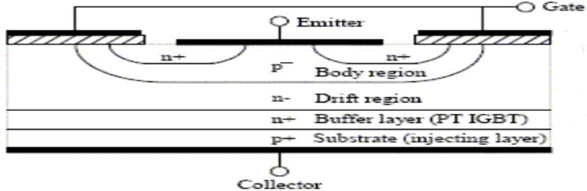
8 IGBT
9 IGBT failure causes Thermal runway Ceramic substrate to base plate solder fatigue, Emitter wire bond fatigue Partial discharge in insulating gel


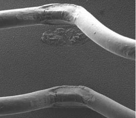
10 Wire bond fatigue


11 Cooling fans failure causes

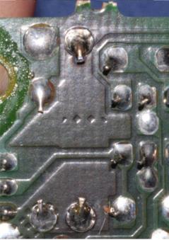
12 PCB failures
13 Failure Mode and Effects Analysis (FMEA) FMECA is composed of two separate analyses, the Failure Mode and Effects Analysis (FMEA) and the Criticality Analysis (CA). IEC defines FMEA as a systematic procedure for the analysis of a system which target is the identification of the potential failure modes, their causes and effects on system performance. CA is necessary to plan and focus the efforts according to set of priorities in order to reduce the risk of failures and give to failures with the highest risk the highest priority. Risk Priority Number (RPN) to each failure mode: RPN=S O D, Where S (Severity) represents the severity on the base of the assessment of the worst potential consequences resulting from an item failure, O (Occurrence) denotes the probability of failure mode occurrence and D (Detection) represents the chance to identify and eliminate the failure before the system or customer is affected.

14 Schematic Diagram of FMECA
15 IEC evaluation criteria for occurrence, severity and detection Occurrence (O) Severity (S) Detection (D) Ranking Failure is unlikely No discernible effect Almost certain 1 Low: Relatively few failures Very minor Very high 2 Minor High 3 Moderate: Occasional failures Very low Moderately high 4 Low Moderate 5 Moderate Low 6 High: Repeated Failures High Very low 7 Very high Remote 8 Very high: Failure is almost unavoidable Hazardous with warning Very remote 9 Hazardous without warning Absolutely uncertain 10
16 PVI FMECA analysis Considering CA, quantitative CA approach is followed up in this paper based on a survey carried out by SunEdison Company that operates more than 600 PV systems in four continents with 1500 in-service inverters from 16 vendors and more than 2.2 million PV modules from 35 manufacturers
17 Frequency of tickets and associated energy loss for each PVI failure mode Specific failure Area Percentage of tickets Percentage of KWh lost Control software 28% 15% PCB board 13% 22% AC contactors 12% 13% DC contactor 4% 1% Fans 6% 5% IGBT modules 6% 5% Capacitors 3% 7%
18 Component failure S O D RPN outage mode IGBT Power Module Possible outage cause Thermal runway High operating Temperature Local effect Cracks formation and delamination formation in solder layers. Final effect Damage of IGBT power module and power interruption Compensating provision against failure Lowering thermal resistance between IGBT and heat sink, DC link Capacitor Capacitor open circuit. Capacitor open circuit. Moisture absorption. -Replacing DC link capacitor & PVI power interruption A proper overload protection scheme. AC/DC contactors Fails to open or open late. Bad system configuration During ON-state: high power losses & degradation of contactor. Overheating, arcs, and fire Periodic visual inspection Cooling fans Mechanical mode Cage damage. Reversed Air flow. Excessive heat. A careful design. PCB Delaminated layers Overheating & moisture between wafer layers Board integrity is reduced Inverter Replacement & interruption of power Proper board design Control software Poor PVI Improper setting parameters. Unreliable MPPT scheme Inefficient operation of inverter Improving inverter data acquisition level.
19 Conclusion Reliability of inverters is still inadequate, but improvements are being in progress. A 5-year warranty has currently become a norm in the industry, whereas 2-year warranties were most common just a few years ago. Unfortunately, these longer warranties are still controversial. The main objective of this work is to provide the manufacturers and decisionmakers in utilities a guide, through FMEA, for the reason and impact of feasible hazards that could interrupt PVI operation and result in losses of power in addition to the prioritizing of these hazards, through CA, for a better maintenance strategies.
20 For further questions: THANK YOU Eng. Abdulla Al Abbasi Sr. Electrical Engineer EWA
21 References Maish, A.B.; Atcitty, C.; Hester, S.; Greenberg, D.; Osborn, D.; Collier, D.; Brine, M., "Photovoltaic system reliability," Photovoltaic Specialists Conference, Conference Record of the Twenty-Sixth IEEE, pp , A review of PV inverter technology cost and performance projections, Navigant Consulting, Burlington, MA, NREL subcontract Rep. NREL/SR , Jan Golnas, A., "PV System Reliability: An Operator's Perspective," IEEE Journal of Photovoltaics, vol.3, no.1, pp , Jan Dhere, N.G., "Reliability of PV modules and balance-of-system components," Photovoltaic Specialists Conference, Conference Record of the Thirty-first IEEE, pp , 3-7 Jan Flicker, Jack; Kaplar, Robert; Marinella, Matthew; Granata, Jennifer, "PV inverter performance and reliability: What is the role of the bus capacitor?," 38th IEEE on Photovoltaic Specialists Conference (PVSC), Volume 2,pp.1-3, 3-8 June 2012.
22 References Federal Office for Education and Science, Mean Time Before Failure of Photovoltaic modules, Final report BBW , June Kaplar, R.; Brock, Reinhard; DasGupta, Sandeepan; Marinella, M.; Starbuck, A.; Fresquez, A.; Gonzalez, S.; Granata, J.; Quintana, M.; Smith, Mark; Atcitty, S., "PV inverter performance and reliability: What is the role of the IGBT?," 37th IEEE Photovoltaic Specialists Conference (PVSC), pp , June 2011.