Manual for Erosion and Sediment Control Updates
|
|
|
- Claud Heath
- 5 years ago
- Views:
Transcription


1 Manual for Erosion and Sediment Control Updates

2 Chapter 1 - The Erosion and Sedimentation Act of 1975 Minor revisions were made to content Existing pictures were replaced with new ones Chapter 2 Sediment and Erosion Control Processes, Principles and Practices Minor revisions were made to content Updated to include new Best Management Practices Existing pictures were replaced with new ones
3 Chapter 3- Planning and Plans Minor revisions were made to existing content Added two new sections: Coordination of Erosion and Sediment Control with Post-Construction Stormwater Management Low Impact Development The Erosion and Sedimentation and Pollution Control Plan has been updated to reflect requirements of O.C.G.A and NPDES Permits
4 Chapter 4 - Local Programs: Principles and Processes Minor revisions were made to existing content Chapter 5 Sources of Assistance and Resource Contact information and maps have been updated
5 Set performance criteria benchmark standards using American Society for Testing and Materials (ASTM) derived testing methods Revised existing BMPs This allows BMPS to be tested and used equally in the same application Updated technical details Redrawn in the 2010 version of auto cad And updated to new coding symbols Added 7 new BMPs
6 Added seven new BMPs Flocculants/Coagulants (Fl-Co)- (Vegetative) Slope Stabilization (Ss) -(Vegetative) Filter Surface Skimmer (Sk)- (Structural) Seep Berm (SpB)- (Structural) Temporary Sediment Trap (Sd4) -(Structural) Turbidity Curtain (Tc)- (Structural) Tree Protection (Tr) - (Structural)
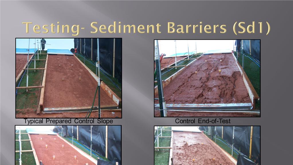
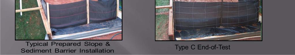
 Tackifiers (Tac) Sediment Barriers (Sd1) Inlet Sediment Traps")
7 Added performance criteria to: Check Dams (Cd) Channel Stabilization (Ch) Slope Stabilization (Ss) Tackifiers (Tac) Sediment Barriers (Sd1) Inlet Sediment Traps (Sd2)
 Rolled erosion control products")
8 Matting and Blanket (Mb) No longer a stand alone BMP, it is now called Slope Stabilization (Ss) This BMP now incorporates: Hydraulic erosion control products (HECP) Rolled erosion control products (RECP)
 using")
9 To be used as a RECP or HECP under the (Ss) category the manufacturer must submit independent research data from rainfall simulated slope tests conducted through the National Transportation Product Evaluation Program (NTPEP) using ASTM D6459.

10 Products wanting to be used on slopes 3:1 or greater shall meet a C-factor (Cover) of.080 or better. The cover factor was determined by the testing of plain straw tacked to the slope. From the original test the c-factor of.087 was recalculated to incorporate terminal velocity.

11 Tackifiers and Binders (Tb), changed to Tackifiers (Tac). Tackifiers are used as a tie-down for soil, compost, seed, straw, hay or mulch. Tackifiers hydrate in water and readily blend with other slurry materials to form a homogenous slurry.

12 There are five types of Tackifiers These blends take into account different blends of synethetic and/or organic polymers. For general use, the tackifier must meet the specifications in Manual. To be used in other BMP applications such as Slope Stabilization or Channel Stabilization please refer to that BMP testing specification.

13 Sediment Barriers (Sd1) There will no longer be Type, A,B,C silt fences. Sediment barriers are categorized as Type Sensitive (Sd1- S) and Type Non-Sensitive (Sd1-NS). Sd1-S is used along state waters and other sensitive areas. The traditionally known silt fence types A,B,C have the potential to now fall into the type-s category depending on testing results.

14 Two rows of type S sediment barrier is still to be used along all state water and sensitive areas but it should be placed at least 36 inches apart. Information is given about the static slicing and the traditional trenching method. This information came directly from EPA. Sediment barriers shall be replaced whenever they have deteriorated to such an extent that the effectiveness of the product is reduced (approximately six months) or the height of the product is not maintaining 80% of its properly installed height.
15 Sediment Barriers (Sd1) incorporate bmps other than silt fence for perimeter control. When a Sediment Barrier is used, the product height in inches for each barrier being used must be shown on the plans. Sediment Barriers must be maintained at half their height regardless of size.
16 Testing- Sediment Barriers (Sd1) Sediment Barriers were tested in accordance with ASTM s WK11340 (as of Feb 2012) except the slope of the test plots was modified to be 3:1, had a 40 ft slope length, and index tests were run on each material. The rainfall sequence for sediment barriers was run according to ASTM D in/hr, 4 in/hr, and 6 in/hr each for 20 minutes. The rain water was tested for turbidity


17 The P-Factor was calculated and reported in accordance with ASTM WK The test soil was classified as a Sandy Clay as shown on the USDA soil triangle. (This is also the same soil that is used in check dam testing and inlet protection testing)
18

19 P-Factor is part of the RUSLE equation.
20 Products seeking approval must meet a P- factor of for sensitive area applications and a P-factor of for non sensitive area applications. Sensitive areas can be defined as any area that needs additional protection, these areas include but are not limited to, state waters, wetlands, or any area the design professional designates as sensitive.
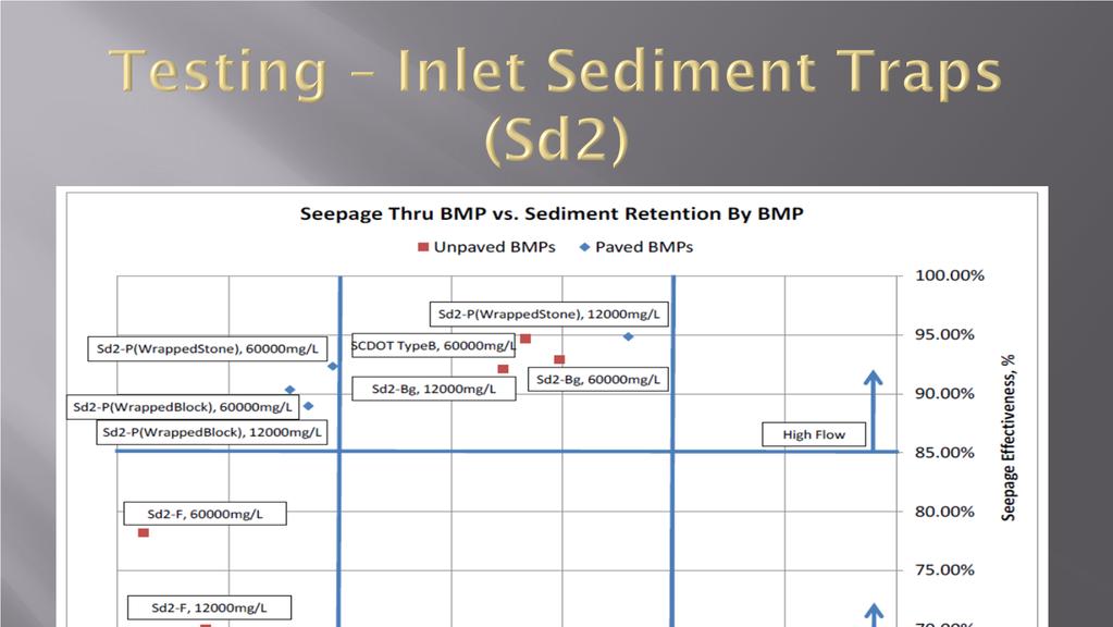
21 Testing Inlet Sediment Traps (Sd2) The large-scale testing reported herein was performed in general accordance with ASTM D 7351 modified to present the flow to an area inlet. For this testing, a simulated area inlet installation comprised of an approximate 24-inch x 24-inch opening simulating a manhole inlet positioned at the center of a containment area was used. The BMP was installed around the opening and exposed to simulated runoff. Sediment-laden water was piped and discharged into the fully contained area around the inlet opening and allowed to run up to and seep through, over, and/or under an installed inlet sediment trap BMP protecting the inlet. The amount (via water and soil weight) of sediment-laden flow was measured both upstream and downstream of the BMP.

22 The measurement of sediment that passes through, over, and/or under the BMP compared to the amount in the upstream flow is used to quantify the effectiveness of the BMP in retaining sediments while allowing continued seepage. The measurement of water that passes through, over, and/or under the BMP compared to the amount of the upstream flow is used to quantify the effectiveness of the BMP in allowing continued seepage. A complete test on each installed BMP with each type of runoff included 3 repeat flows, or events, separated by not less than 4 hours.


23 Testing was done for both paved and unpaved applications.

24 Inlet sediment traps shall meet : 90% soil retention efficiency with a minimum seepage efficiency of 65% for unpaved areas 75% soil retention efficiency with a minimum seepage of 85% for paved areas.

25

26 Through testing there are two different categories (high retention and high flow) supported. In areas where BMPs are being used on paved surfaces, or safety is a concern, the potentially negative effects of ponding should be taken into account. In such cases, a high flow BMP is preferred.
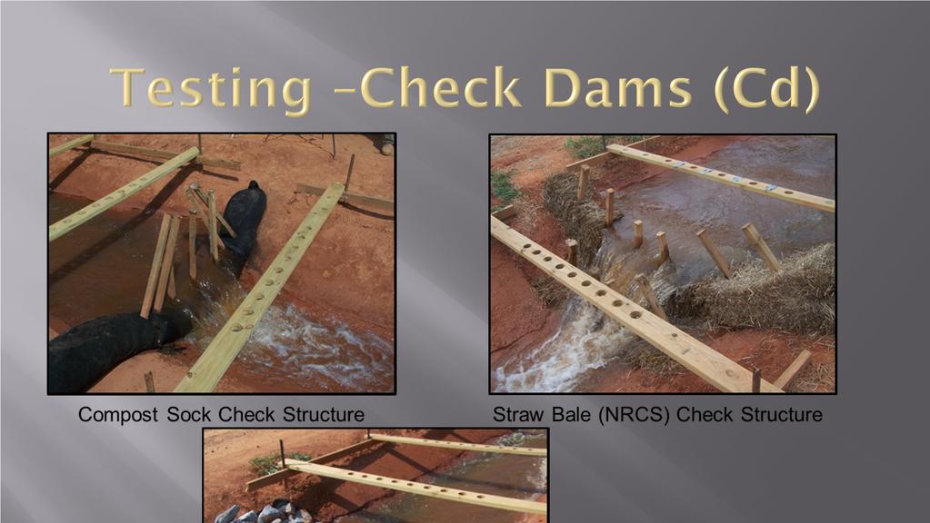
27 Check Dams (Cd) Most notable change in check dams is the installation of the straw bale check dam.


28 ASTM D7208, Determination of Temporary Ditch Check Performance in Protecting Earthen Channels from Stormwater-Induced Erosion (Modified)
29 Trapezoidal shaped flume with a 2 ft wide bottom and 2:1 side slopes and a 5% bed slope. The test channel is 60 ft long: 40 ft test section + 10ft upstream and a 10 ft downstream transition sections. Concentrated flow produced by opening a valve to allow gravity flow from an adjacent pond. Each test is run at a single predetermined flow rate for 30 minutes.
30 Flow is metered into the channel via a calibrated sharp-crested weir. 9 evenly spaced cross-sections within the test section and 9 evenly spaced measurement points at each cross-section to enable pre and post measurements of the soil surface.

31
32 The check dam must perform better than the unchecked channel 20% of control (i.e. 80% reduction in soil loss), and withstand a flow rate of 2.0cfs.
 Vegetated Lining with TRM or Rip Rap Lining Category 3 (> 10 ft/sec) Concrete Lining *equivalent shear stress can also be")
33 Channel Stabilization (Ch) Products will be categorized as followed: Category 1 (0-5 ft/sec) Vegetated Lining with Blankets Category 2 (5-10 ft/sec) Vegetated Lining with TRM or Rip Rap Lining Category 3 (> 10 ft/sec) Concrete Lining *equivalent shear stress can also be used.
 Performance in Protecting Earthen Channels from Stormwater-Induced")
34 Products seeking use for channel stabilization applications must be tested according to ASTM D Standard Test Method for Determination of Rolled Erosion Control Product (RECP) Performance in Protecting Earthen Channels from Stormwater-Induced Erosion.

35 Floating Surface Skimmer (Sk): A skimmer drains the water from the top allowing cleaner less turbid water to discharge from the ponding area. Emergency spillway is required when using a skimmer. Can replace the riser pipe as the principal spillway. If a skimmer can not be used a rationale/justification must be given.
 width in feet (top and bottom) and depth Time to Drain (hrs) Skimmer Dimensions (orifice and head size in")
36 Floating Surface Skimmers require the following to be shown on the erosion control plan: Pond, trap or basin size, length in feet (top and bottom) width in feet (top and bottom) and depth Time to Drain (hrs) Skimmer Dimensions (orifice and head size in inches)

37 Seep Berm (SpB) A seep berm is a linear control device constructed as a diversion perpendicular to the direction of the runoff to enhance dissipation and infiltration of runoff, while creating multiple sedimentation chambers with the employment of intermediate dikes. To allow the 2 year storm event, 24 hour design storm to seep out while allowing larger flows to be diverted to a sediment storage area
 H.")
38 Seep Berm require the following to be shown on the erosion and sediment control plan: A. Top of Berm Elevation in feet* B. Bottom of Berm Elevation* C. Top of Berm Width * D. Height of the Berm* E. Seep Hole Diameter* F. Distance from the top of the berm to the seep to be placed in accordance with the 2yr- 24hr storm* G. Type of Seep PVC Metal Other(specify) H. Spacing of Seep Along the Berm* * shown in feet

39 Temporary Sediment Trap (Sd4) BMP added to provide sediment storage options for smaller sites All sd4 s to be cleaned out at 1/3rd full Provides three options: 1. Temporary Sediment Trap Overflow 2. Temporary Sediment Trap Combination Outlet 3. Temporary Sediment Trap Rock Outlet
40 1. Temporary Sediment Trap - Overflow (Sd4-A) An overflow temporary sediment trap is limited to small areas less than 1 acre, The maximum life span of an overflow trap is 6 months. Silt fence, straw bale barriers or grass filter strips are used to polish the overflow water as it leaves the sediment trap.
41 2. Temporary Sediment Trap Combination outlet (Sd4-B) The combination outlet uses straw bales and silt fence to dewater the sediment trap. Proper installation and staking of the straw bales, and wire backing on the silt fence are required for the materials to resist 1 foot or more of ponded water. The combination straw bale and silt fence outlet is limited to 1 acre total drainage area, and has a life span of less than 1 year.
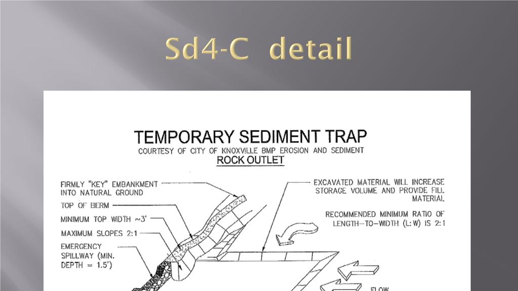
42 3. Temporary Sediment Trap Rock outlet (Sd4-C) The rock outlet relies on filtering through layers of aggregate, rock or riprap material to dewater the sediment trap. It is the most sturdy of the sediment trap designs and generally requires less maintenance. It can be used for drainage area up to 5 acres and has a life span of 1 year.

43

44 Turbidity Curtain (Tc) A floating or staked barrier installed within the water. (It may also be referred to as a floating boom, silt barrier or silt curtain). Not to be used as sediment storage. Turbidity Curtain is installed to minimize turbidity and silt migration from work occurring within the water or as a supplement to perimeter control BMPs at the water s edge. Silt or turbidity is confined to the area within the boundary created by the installation, such that suspended particles drop out of the water column over time.

45 Staked Turbidity Curtains Tc-S Floating Turbidity Curtains Tc-F

46 Tree Protection (Tr) To protect desirable trees from injury during construction activity. Tree Protection Zones: 1. Measure the diameter of the tree trunk in inches at 4.5 feet from the ground. This is called the Diameter Breast Height or DBH. 2. Multiply this value by 1.5. This result is the diameter of the root protection zone in feet. This is also considered the critical rooting distance.


47 BMPs are used in series to provide a defense against erosion on land disturbance sites using both vegetative and structural measures