PRELIMINARY DRAINAGE STUDY
|
|
|
- Prosper Johnson
- 5 years ago
- Views:
Transcription


1 PRELIMINARY DRAINAGE STUDY FOR BIG ROCK CLUSTER SOLAR FARMS PREPARED FOR: Daniel Kolta 90FI 8me LLC & 92JT 8me LLC 211 Sutter Street, Fl. 6 San Francisco, CA Prepared Revised Revised Revised Revised
2 Table of Contents 1 INTRODUCTION Purpose 3 2 LOCATION 3 3 SITE CONDITIONS AND PROPOSED DEVELOPMENT 5 4 FEMA FLOODPLAIN CLASSIFICATION 7 5 STORMWATER MANAGEMENT Existing Drainage Conditions Proposed Drainage Conditions Retention Basin Calculation Parameters Retention Basin Sizing 9 6 CONCLUSIONS 11 7 REFERENCES 11 List of Figures Figure 1: Project Vicinity Map 4 Figure 2: Project Site Map 5 List of Tables Table 1: Laurel Project Parcels 6 Table 2: Big Rock Project Parcels 6 Table 3: Retention Basins 10 Exhibits Exhibit A FEMA FIRM Panel Exhibit B FEMA FIRM Panel Exhibit C Onsite Drainage Map Big Rock 1 Site Exhibit D Onsite Drainage Map Laurel 1 and Por. of Laurel 2 Sites Exhibit E Onsite Drainage Map Por. of Laurel 2 and Por. of Laurel 3 Sites Exhibit F Onsite Drainage Map Por. of Laurel 3 Site Exhibit F Onsite Drainage Map Por. of Laurel 3 Site 2
3 1 INTRODUCTION 1.1 PURPOSE The purpose of this drainage report is to present the drainage criteria, methodology and analysis of on-site drainage conditions, in support of the Big Rock Cluster Solar Farms, and to provide recommendations for drainage and grading concepts for the proposed site development. This report addresses the recommended on-site drainage facilities by: Establishing drainage design criteria and concepts. Describing the existing and proposed drainage patterns. It is established in this drainage study that each field will act as its own retention basin and supported by the hydrology and hydraulic calculation it is determined that each field has the capacity to retain the volume resulting from calculating a laminar flow of 3 inches of rain over the entire tributary area to each agricultural field. The drainage design will be conducted in accordance with the County of Imperial s design criteria, which establishes that 100% of the 100-year storm (3 inches of rain) will be stored on-site and released into the IID drainage system using existing drainage connections. Calculations were performed according to the methodology and procedures outlined in the County of Imperial Department of Public Works Engineering Design Guidelines Manual for the Preparation and Checking of Street Improvements, Drainage and Grading Plans with Imperial County, Included in the appendices are the on-site drainage maps and retention calculations. 2 LOCATION The Big Rock Cluster Solar Farms consist of four Solar Sites; Big Rock Site, Laurel 1, Laurel 2 and Laurel 3 Sites. The Project Sites are located south of Interstate 8, west of Drew Road and Vogel Road, north of Mandrapa Road and east of Hyde Road in the Imperial Irrigation District Area. The Project Sites are approximately eight miles southwest of the City of El Centro, three miles south of 3

4 Seeley and fourteen miles west of Calexico, in the unincorporated area of the Imperial County, in the State of California. The project lies within Sections 21, 22, 26, 27, 28, 34, and 35 of Township 16 South, Range 12 East, San Bernardino Meridian. The Project Vicinity Map, and the Project Site Map are graphically shown in figure 1 and Figure 2. Figure 1: Project Vicinity Map 4

5 Figure 2: Project Site Map 3 SITE CONDITIONS AND PROPOSED DEVELOPMENT The project area consists of eighteen (18) agricultural parcels, encompassing approximately 1380 gross acres (see table 1). The topography of the Project Sites is relatively flat The Project Sites have been historically used as farmland. On the high side of each farm field are concrete lined or earthen irrigation canals used to flood irrigate the farm fields. Tailwater ditches generally flow north or south to convey the excess irrigation water and storm water runoff to existing concrete drain boxes and 12 concrete discharge pipes that drain into Imperial Irrigation District (IID) drains. Elevated dirt field access roads run along the perimeter of the farm fields. There are existing houses/buildings in the vicinity of the project area, and one existing abandoned farm homestead is located just outside the southwesterly corner of the Big Rock Site project boundary that is not part of the project. 5
6 Table 1 LAUREL PROJECT PARCELS (1,038 acres) OWNER APNs AREA (ACRES) PROJECT ZONING Pearl Evans, LLC Laurel 1 A-2-R Nancy and JC Nale Laurel 1 A-2-R Kuhn Laurel 2 A-2-R (portion) Kuhn Laurel 2 A-3 Kuhn Laurel 2 A-2-R Kuhn Laurel 2 A-2-R Preece Laurel 3 A-2-R (portion) Preece Laurel 3 A-2-R Preece Laurel 3 A-2-R Preece Laurel 3 A-2-R Preece Laurel 3 A-2-R (portion) Preece Laurel 3 A-2-R Childers Laurel 3 A-3 Table 2 BIG ROCK PROJECT PARCELS (342 acres) OWNER APNs AREA (ACRES) PROJECT ZONING Carolyn Childers Big Rock 1 A Carroll Childers Big Rock 1 A-3 Norma Hampton Big Rock 1 A-3 And Carroll Childers Scopesi Big Rock 1 A-2-R The project is being developed as four photovoltaic energy solar farms. Proposed improvements to the sites will include construction of approximately 325 MW-AC photovoltaic energy facility, step up transformers, and perimeter and interior roads for operations and maintenance. The power generated by the project will be delivered from the project sites via up to 230 KV overhead and/or underground electrical transmission line(s) originating from an on-site substation(s) switchyard(s), and terminating at the proposed Imperial Irrigation District (IID) Fern Substation. In the alternative, power may be delivered to the San Diego Gas & Electric (SDG&E) Imperial Valley Substation, Drew Switchyard, or Imperial Solar Energy Center West Substation. There are three IID delivery canals in the vicinity of the project site. The Westside Main Canal runs east/west along the south side of the Big Rock 1 Site and along the south side of Laurel 3 Site. The Fern Canal runs north/south along the west side of the Big Rock 1 Site and Laurel 2 Site and along the eastside of Laurel 3 6
7 Site. The Fig Canal runs west/east along the north side of the Big Rock 1 Site and then turning north along the west side of the Laurel 1 Site. There are six IID drains along/near the project limits that collect excess irrigation and storm water. The Fig Drain runs north along the east side of the Big Rock 1 and Laurel 1 Sites. The Diehl Drain runs north along the west side of the Laurel 1 Site and along the east side of the Laurel 2 Site, then turns east along the north side of the Laurel 1 Site. The Wixom Drain that runs north along the west side of the easterly portion of Laurel 2 Site and along the east side of the westerly portion of the Laurel 2 Site, and along the west side of the Big Rock 1 Site. The Dixie Drain that bisects the Laurel 3 Site. The Dixie Drain No. 3C that service the easterly portion of Laurel 3 Site and runs north along the west side of the westerly portion of Laurel 2 site. The Dixie Drain 3-D runs west/east along the south side of Laurel 3 Site. It is established in this drainage study that each field will act as its own retention basin and supported by the hydrology and hydraulic calculation it is determined that each field has the capacity to retain the volume resulting from a laminar flow of 3 inches of rain over the entire tributary area to each agricultural field. 4 FEMA FLOODPLAIN CLASSIFICATION The project site is located on the FEMA FIRM Panel 2050 of 2300 Map Number 06025C2050C and on the FEMA FIRM Panel 1700 of 2300 Map Number 06025C1700C effective September 26, 2008 in Zone X. The FEMA un-shaded Zone X designation is an area determined to be outside the 0.2% annual chance floodplain. The FIRM panels are included in Exhibit A and Exhibit B. 5 STORM WATER MANAGEMENT 5.1 Existing Drainage Conditions The existing farm fields are graded to compounded planar slopes. Generally, the fields slope from east to west at slope percentage rates between 0.10% to 0.20% and north or south at slope percentage rates between 0.10% to 0.20%. The very flat topography allows for the irrigation water to move slowly over the field and promote absorption in the existing clay soils. Irrigation tailwater outlet boxes and 12 diameter concrete pipes drain the excess irrigation tailwater and storm event runoff water to the IID drains at all low areas for each farm field. Elevated field roads or drain bank maintenance roads that 7
8 are graded to about one foot above the adjacent farm field, are located at the low ends of each field. Based upon review of the existing topography, it is determined that off-site run off does not enter the project development areas due to the presence of physical features presenting barriers to the off-site flow (County Roads, IID Canal and Drains and private field roads). Off-site storm water may pond up against these facilities and since the off-site flow patterns will be maintained it has been determined (based on existing topography) that the off-site drainage has no impacts on the project site, therefore analysis of off-site drainage run off is not part of this study. On-site retention will be provided to maintain the existing drainage conditions to handle the 100-year storm water flows to exit the site by means of the existing IID outlet discharge structures. In most of the farm fields there is an existing subsurface tile drain system used to remove salts accumulating from agricultural irrigation and crop production. The existing tile drain pipes are located approximately 5 to 8 below existing grade. The tile drain system is not used in the agricultural fields of the projects. The existing site tile drain systems will remained in place and will only be removed from the site if they are in conflict with permanent structures (such as transmission power poles, collection systems, substation equipment etc.) 5.2 Proposed Drainage Conditions In proposed conditions, the site will be developed with solar arrays, fencing, access road and O&M Buildings. The private irrigation delivery ditches within the project sites may be removed for the installation of the solar arrays, but the farm fields will generally remain at their existing grades and flow patterns will remain unchanged. The ground below the solar panels will not be an impermeable surface; rainwater will run off of the panels and fall to the earthen surface. Within and around the arrays 20 wide fire access roads will be constructed. The drainage analysis is based on on-site volumes and will include the amount of storm water generated by the 100-year storm (3 inches of rain) and it is assumed that 100% of the 100-year storm (a C factor of 1) will be retained on site. Each field was analyzed separately based on the volume of runoff generated from 100-year storm (3 inches of rain). The division of each field is presented on Exhibits C to G, of the On-site Drainage Maps. The existing IID drain connections and existing 12 diameter concrete discharge pipes will be utilized to drain out the fields. Based on the calculated retention 8
9 volumes required, the existing perimeter roads and berms will be maintained (some berms will need to be raised during the grading activities to provide sufficient detention in the sub-sites where the existing perimeter roads and berms are not high enough). This design maintains the existing drainage patterns for each field and the raised roads and berms will retain the runoff volume resulting from 100-year storm (3 inches of rain). Retention basin calculations have been provided in Exhibits C to G and in Table 3. All on-site storm water contributions will be handled individually by every parcel that comprises the project. No storm water contributions will be disposed on to any County Public Right of Way. The field after a 100 year storm event should empty within 72 hours in order to provide mosquito abatement. If this is not possible then the owner should provide a mosquito abatement plan to the satisfaction of the Environmental Health Services Department (EHS). All existing outlet discharge pipes will be upgraded (if required) in accordance with IID Standards to satisfy the requirements of the Hydrology/Hydraulic analysis preformed by IID for the agricultural base flow conditions and the modeling scenario for the 100yr-24hr rainfall event contributions to the existing drain systems within the project area. 5.3 Retention Basin Calculation Parameters Hydrologic calculations are made in accordance with the following parameters: 1. The total volume retained will be 100% of the 100 year storm (3 inches of rain). 2. Retention will be provided in ponding areas within the project under the proposed solar panel arrays, next to the existing IID drain connection for each field. 5.4 Retention Basin Sizing The retention basins are sized according to the County of Imperial Public Works Department Drainage Design Criteria: The volume is calculated using the following equation: 9
10 V=A x P x C Where V= Required storage volume in Cubic Feet A= Area of the basin in Acres P= Precipitation depth in inches C= Runoff coefficient reduction factor (1) Table 3 - Retention Basin Sizing Basin Drainage Area (AC) Storage Required (AC-FT) Storage Provided (AC-FT) Big Rock Site B B B B B B Laurel Site L L L L L L L L L L L L L L L * L
11 6 CONCLUSIONS This drainage study report was prepared in accordance with the County of Imperial s design criteria that establishes that 100% of the 100-year storm (3 inches of rain) will be stored on-site and drainage be released into the IID drainage system using an existing drainage connection. Additionally the following facts were considered in the preparation of the drainage report: Each Sub-Site basins will retain its own drainage and the field will act as a retention basin. The drainage stored in the parcel will be released in less than 72 hours or else a mosquito abatement plan shall be implemented. Earthen berms will be provided to ensure the drainage is retained on-site. Connections to existing IID drainage facilities will be done according to the Imperial Irrigation District standards and according to the encroachment document conditions. It has been determined that off-site drainage from existing roads and adjacent fields have minimal or no impacts on the on-site drainage retention capacity. 7 REFERENCES County of Imperial Department of Public Works, Engineering Design Guidelines Manual for the Preparation and Checking of Street Improvements, Drainage and Grading Plans within Imperial County, September
12 Exhibits


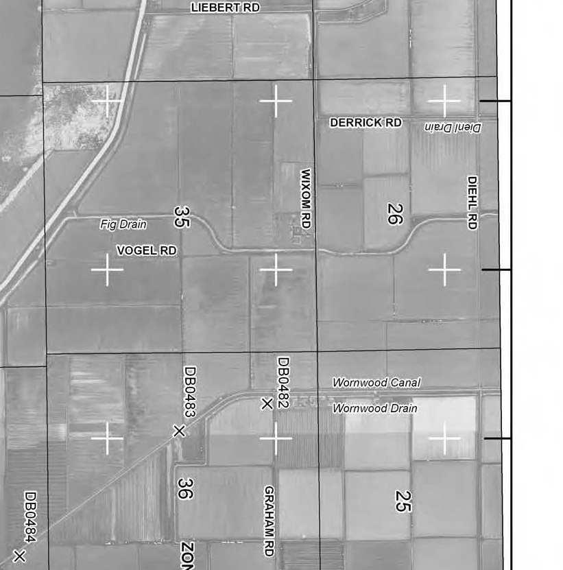

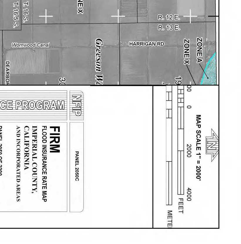
13 BIG ROCK 1 LAUREL 1 LAUREL 2 LAUREL 3 EXHIBIT A FEMA FIRM PANEL


14 LAUREL 1 LAUREL 2 LAUREL 3 EXHIBIT B FEMA FIRM PANEL


15 WEST SIDE MAIN CANAL LIEBERT ROAD DC2 DC3 B6 B2 B3 DC1 B5 B1 FIG DRAIN B4 DC5 DC4


16 DC2-1 L2-1 DERRICK RD DC1-1 JESSUP RD DC2-2 L2-2 DIEHL DRAIN L1-1 DIEHL RD DIEHL RD DC1-2 DIEHL DRAIN L1-2 DC1-3 L1-3 L1-4


17 DC2-3 DC2-4 L2-4 L2-3 JESSUP RD VAUGHN RD DC3-2 DC3-1 L3-2 L3-1 DC3-3 L3-3 DIXIE DR JESSUP RD


18 DC3-5 L3-4 WESTSIDE RD L3-5 DC3-4 VAUGHN RD DC3-6


19 WEST SIDE MAIN CANAL DC4 VAUGHN RD DC3-7 L3-7 DIXIE DR L3-8 L3-6 DC3-6 WESTSIDE RD