Fuel Cell Technology
|
|
|
- Roberta Morrison
- 5 years ago
- Views:
Transcription
1 Fuel Cell Technology TFRF05 Docent Jinliang Yuan October 30, 2008 Department of Energy Sciences, Lund University, Sweden
2 Lectures: Docent Jinliang Yuan Home Works/Design Tasks: Dr. Jinliang Yuan s: Division of Heat Transfer, Department of Energy Sciences, Faculty of Engineering (LTH), Lund University Home Page:
3 Course Objectives to provide deeper knowledge, a wider scope and improved understanding of theory, analysis, performance, design and the operational principles of various fuel cell components, systems, fuel processing and hydrogen infrastructure; To understand the current state of technology of stationary, automotive and portable fuel cell systems and components, and the challenges the industry faces today. The design and analysis emphasis will be on the thermodynamics, heat transfer and some heat exchanger design for all thermal systems and subsystems.
4 Course Contents Various fuel cells, including SOFC, PEMFC, AFC, DMFC, etc; Various levels: from cell components, unit cells and stacks, further to fuel cell systems; Other components to balance fuel cell systems, such as HEX, reformers, thermal, gas and water management, etc.
5 Course Literature Compendium: Complementary Course Stuff for Fuel Cell Technology; Book chapters selected from various books on specific topics; Free of charge for this year participants.
6 Course Organization The course is given in form of lectures, home assignments and a small project. The home assignments aim to give proficiency in applying the fundamental theories on fuel cell engineering problems. The project aims to provide a further improved understanding by a short literature survey on a relevant topics, analysis and calculations. The project shall be presented in form of a report 8-10 pages (Appendices excluded).
7 Home Assignment and Project Work Each student will be assigned a paper for a critical summary and a discussion. All students will be expected to have read the paper and participate in the discussion. A mark will be assigned for the critical summary as well as for participation. Project Work: to analyse or design a fuel cell related process, system or component by a short literature survey on a relevant topic, analysis and calculations.
8 Examination and Grading The exam will be a 30 minute individual oral examination on the topics of the course subjects. Assignment (paper discussion) Project progress Report Project Final Report Project Oral Presentation Oral Examination Total 10p 10p 45p 15p 20p 100p To pass the course, you need at least 50p. Grade 3: 50p, grade 4: 70p and grade 5: 90p..
9 Date Day Time Activity Topics to be Covered Room Thursday 8-10 Lecture Friday 8-10 Lecture Introduction of the Course, Course Outline and Basic Information on Fuel Cell Technology Efficiency and Open Circuit Voltage I M4128 M Tuesday 8-10 Lecture 6.11 Thursday 8-10 Lecture Efficiency and Open Circuit Voltage II Operational Fuel Cell Voltages Friday 8-10 Home Study AFC+ DMFC M4128 M Tuesday 8-10 Discussion Discussion Papers M Thursday 8-10 Lecture PEM Fuel Cells I M Friday 8-10 Home Study MCFC
10 18.11 Tuesday 8-10 Lecture PEM Fuel Cells II M Thursday 8-10 Lecture Solid Oxide Fuel Cells M Friday 8-10 Home Study Fuel Cell Modeling I Tuesday Submission Project Progress Report Thursday 8-10 Lecture Fuels and Fuel Reforming M Friday 8-10 Home Study Fuel Cell Modeling II 2.12 Tuesday 8-10 Lecture Thermal Management and Heat Exchangers 4.12 Thursday Submission Project Final Report M Tuesday 8-10 Lecture Balance of Plant M Thursday 8-10 Presentation Project Oral Presentation M Monday 8-12 Exam Oral Exam M5113
11 Fuel Cell Technology Why we need and what is fuel cell? How does fuel cell work? To make it work, what are required? Better than other energy systems? Why not available everywhere? Problems and major limitations?

12 Evolution of Land Transportation Land Transportation Horses Hay Agriculture Sunlight Land Transportation Steam Locomotive Coal Coal Mine Coal Land Transportation Gasoline Vehicles Gasoline Oil Refinery Oil Land Transportation Fuel Cell Vehicles Hydrogen Steam Methane Reforming Natural Gas Hydro Electrolysis Wind Sunlight Uranium
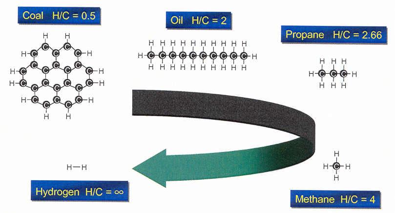
13 Decarbonization of Fuels
14 Electrochemical Power Systems There are two types of Electrochemical power systems, namely, secondary (or rechargeable) storage battery and fuel cells: A storage battery consists of an assemblage of secondary cells which are chemically reversible to a degree that permits electrical recharging; A fuel cell consists of two electrodes (usually porous) which can catalyze the conversion of a particular fuel (hydrogen, methanol, hydrazine) and an oxidant to electricity. Power can be drawn from the cell as long as fuels are supplied and the reaction products are removed.
15 Battery Vs. Fuel Cell Batteries store electricity and require a plentiful supply of outside electricity to function; Fuel cells make electricity and require a plentiful supply of fuel. Fuel cells can be refuelled in minutes in much the same way as an internal combustion engine. It is the major advantage over batteries. There are problems in finding cheap organic fuels, and more especially in discovering an inexpensive and efficient catalyst to replace noble metals for the oxidation of low-grade hydrocarbon fuels; longer starting time. Lots of efforts put on battery-fuel cell hybrid power system, particularly for vehicles.
16 Batteries There are over 30 battery systems proposed and developed for electric vehicles, and they are classified by the nature of electrolyte used: Aqueous solution (acidic or alkaline). Such as lead-acid, nickel-based (Ni-Zn, Ni-Fe, Ni-H2, Ni-Cd), metal-air (Fe-air, Zn-air, Pb-air, Cd-air, Li-air, etc.), and zinc-halogen (Zn-Cl2, Zn-Br2) systems. Molten salt. The sodium-sulphur and lithium-sulphur systems are the most technologically developed. Organic liquid. These systems are based on the use of lithium as the high energy negative electrode. Solid compound. For the purpose to avoid the problems encountered with liquid constituents, e.g., corrosion, structure changes on cycling, seal failure, need of careful maintenance, etc.

17 General architecture of a battery system
18 Various Processes in Batteries There are various electrochemical and physical processes occurring inside battery to affect the charge and discharge performance of batteries. including electrochemical kinetics, mass transport in porous electrodes and free electrolyte, fluid flow and thermal effects. Various developed models provide the detailed information of concentration and current distributions, and charge and discharge curves. The simulation results yield significant insight into responses of battery to various charge and discharge modes, and thus help to design optimal charge algorithms.

19 Example: Detailed Structure of a Li-ion Battery


20 History First demonstration in 1839 by Sir William Grove SOFC began with Nernst s discovery of solid-state ionic conductor in First PEFC developed by General Electric in the 1960 s for NASA s Gemini Space program. William Grove First demonstration in 1839 by separate platinum electrodes in oxygen and hydrogen submerged in a dilute sulfuric acid electrolyte solution

21 Dr. Harry Karl Ihrig tilling hard dry earth with a plow and fuel cell-driven tractor in the fall of 1959.
22 Fuel Cell System Source: Presentation from Fuel Monash Cell Technoloogy University, Australia, 2001
23 Fuel including sulphur Automotive PEM-System Operated On Gasoline Exhaust Water (For Cooling) GT Air DeS Fuel + H2S Steam and air ~ 0.1 kg/kw (including H2S-trap) Mixing chamber ATR HTS H2S-trap LTS PrOx/Selox 400 C 800 C 400 C 350 C 200 C 150 C Condenser Superheater Evaporator ~ 0.2 kg/kw ~ 0.2 kg/kw Cat.- Bypass at high CO Burner A Preheater ~ 0.3 kg/kw ~ 0.2 kg/kw 650 C Air Adapted from Volkswagen presentation, 2002 C 80 C PEM-FC CP Water Air

24 Industrial coproducts Pathways to Hydrogen Source: Presentation from Monash University, Australia, 2001
25 How a Fuel Cell Works Air Fuel Cell + Hydrogen - Electricity Simplified Version

26 Various Power Technologies

27 Typical Early Ballard Fuel Cell Stack


28 Fuel Cell Stack Assembly Hydrogen Hydrogen Flow Plate Proton Exchange Membrane Air Flow Plate Air
29 An 90 kw Fuel Cell System
30 G o and o V for hydrogen fuel cells o V Form of product Tem. ( o C) G o (V) Liquid Gas Gas Gas Gas Gas V oc o = V + RT nf ln P P H2 O2 P H2O 1/2 o o o o ΔG ΔH TΔS V = = nf nf V oc -Open Circult Voltage
31 Voltage/Power Density vs. Current Density
32 What happens when a fuel cell is applied a load? Polarisation curve 1,2 1 Activation over potential region V Potential [V] 0,8 0,6 0,4 Ohmic over potential region Cocentration over potential region 0, ,2 0,4 0,6 0,8 1 1,2 i [A /c m 2 ] Dependant mainly upon temperature, pressure and concentration of species.
33 Fuel Cell Types The most common classification of fuel cells is by the type of electrolyte used in the cells. The choice of electrolyte dictates the operating temperature range of the fuel cell, determining the physicochemical and thermomechanical properties of materials used in the cell components The operating temperature also plays an important role in dictating the degree of fuel processing required. In low-temperature fuel cells, all the fuel must be converted to hydrogen prior to entering the fuel cell. In addition, the anode catalyst in lowtemperature fuel cells is strongly poisoned by CO. In high-temperature fuel cells, CO and even CH 4 can be internally converted to hydrogen (internal reforming) or even directly oxidized electrochemically.
34
35 PEMFC-Proton Exchange Membrane Fuel Cell Anode Input e - or PEFC-Polymer Electrolyte Fuel Cell Cathode Input AFC H 2 H 2 O OH - O 2 (+H 2 O) T=80 o C PEMFC PAFC H 2 H + O 2 H 2 O T=80 o C T=200 o C MCFC H 2 CO 2 H 2 O CO 3 2- O 2 CO 2 T=650 o C SOFC Anode Output H 2 H 2 O O 2- O 2 T>700 o C Cathode Output SOFC- Solid Oxide Fuel Cell Anode Electrolyte Cathode

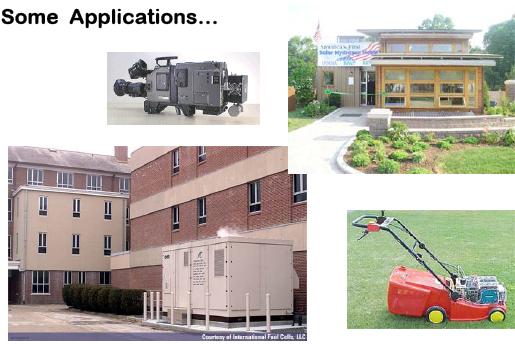
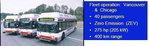
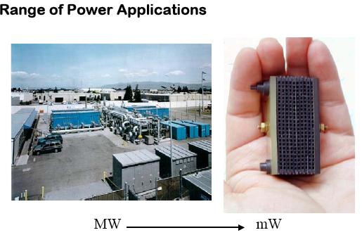
36 Potential Applications Source: Arthur D. Little Presentation, 2000
37

38


39 Fuel Cells in the Ocean & in Space
40
41

")
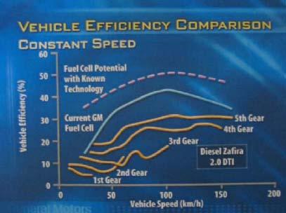
42 Example: Automotive Fuel Cell Source: P. Pei et al., Int. J. Hyd. Eng., 2004 (29)
, typically given in W/cm 2. Another key figure is power density, i.e., power/volume or power/mass.")
43 Key Parameters to Compare Fuel Cell Performance The key figure is the current per unit area, always known as the current density, in A/cm 2 based on a specific operating voltage, typically about 0.6 or 0.7 V. These two numbers can then be multiplied to give the power per unit area (or specific power), typically given in W/cm 2. Another key figure is power density, i.e., power/volume or power/mass. The most common units are kw/m 3 and W/kg, respectively. The cost is in US dollars per kilowatt. The lifetime is given as the percentage deterioration per hour. The gradual decline in voltage is also sometimes given in units of millivolts per 1000 hours. Fuel cell efficiency is not at all a straightforward figure.
44 Other Parameters The cost per kilowatt and the power density. Current internal combustion engine technology is about 1 kw/l and $10 per kw. Such a system should work for about 4000 h (about 1 hour use each day for over 10 years). For combined heat and power systems the cost is still important, but a much higher figure of $1000 per kw is the target. The cost is raised by the extra heat exchanger and grid connection systems, and because the system must withstand much more constant usage 40,000 hours use is a minimum.

45 SOFC Working Principles
 0.5O 2 +2e - -- O 2- (exothermic) Steam reforming is 42 times faster than electrochemical reaction @900 o C; 7.")
46 Various Reactions: CH 4 +H 2 O -- CO+3H 2 (endothermic) CO+H 2 O -- CO 2 +H 2 (exothermic) Various Reactions (conventional SOFC) H 2 +O H 2 O+2e - (exothermic) 2CO+O CO 2 +4e - (exothermic) 0.5O 2 +2e - -- O 2- (exothermic) Steam reforming is 42 times faster than electrochemical o C; 7.2 times o C.

47 PEMFC Working Principles
48 PEMFC Schematic Electrical Current Flow Vehicle Loads 2e - 2e - Active Catalyst Layer Membrane Electrode Assembly Water, nitrogen, excess air Out Flow Field Plate Section H 2 In H 2 2H + Gas Diffusion Backing Layer Proton Exchange Membrane 2e - 2e - 2e - 2H + Proton Exchange Membrane H 2 O O -- 1/2O 2 Flow Field Plate Section Air In
 H 2 -- 2H + + 2e - (exothermic) In Overall: H 2 +0.")
49 Various Reactions (PEMFC) Various Reactions: 4H + +O 2 +4e H 2 O (exothermic) H H + + 2e - (exothermic) In Overall: H O 2 -- H 2 O

50 The construction of anode/cathode assemblies with edge seals. These prevent the gases to leak in or out through the edges of the porous electrodes. The electrolyte is larger than one or both of the electrodes and fits a Fuel sealing Cell Technoloogy gasket around each electrode.

51 The electrodes are made flat, and the structure is porous so that both the electrolyte from one side and the gas from the other can penetrate it to give the maximum possible contact between the electrode, the electrolyte, and the gas. In above figure, the electrons are flowing from the anode to the cathode. The cathode is thus the electrically positive terminal, since electrons flow from to +. Often the cathode is defined as the negative electrode in an electrolyte cell or electron valve or tube, and the positive terminal of a primary cell such as a battery.
52 Activation Energy and Reaction At the anode, hydrogen reacts to release energy with limited rate. It is so because the activation energy must be supplied to get over the energy hill. If the probability of a molecule having enough energy is low, then the reaction occur slowly. There are three ways to increase reaction rates: the use of catalysts, raising the temperature, increasing the electrode area.
53 Tranport Processes in a Cathode Proton Catalyst Electrical Fibers Membrane Catalyst Layer Porous Layer

54 Carbon Paper Porous Layer

55 Fluid Transport Path in a Porous Electrode
56 Effective Surface Area The reaction is sometimes called the three phase contact between electrode/electrolyte/gas The rate will be proportional to the area of the electrode, and the performance is often evaluated by the current per cm 2. The straightforward area (length width) is not valid due to its highly porous, instead the effective surface area. Modern fuel cell electrodes with microstructure have surface areas hundreds or even thousands of times bigger. In addition the electrodes may have to incorporate a catalyst.
57 Importance of Three-phase Interfaces Three-phase interfaces are microscopic regions for actual electrochemical reactions. For a interface to be active, it must be exposed to the reactant, be in electrical contact with the electrode, be in ionic contact with the electrolyte. It contains sufficient electro-catalyst for the reaction to proceed at the desired rate. The density and the nature of these interfaces play a critical role in the electrochemical performance of fuel cells.
58 High Performance Interface In solid electrolyte fuel cells, the challenge is to engineer a large number of catalyst sites into the interface Catalyst sites are electrically and ionically connected to the electrode and the electrolyte, respectively, and that is efficiently exposed to the reactant gases. In most successful solid electrolyte fuel cells, a highperformance interface requires the use of an electrode having mixed conductivity (i.e., it conducts both electrons and ions).
59 Electrolyte Functions The electrolyte transports dissolved reactants to the electrode, and conducts ionic charge between the electrodes to complete the cell electric circuit. It also provides a physical barrier to prevent the fuel and oxidant gas streams from directly mixing.
60 Electrode Functions to conduct electrons away from or into the three-phase interface once they are formed (materials having good electrical conductance), to provide current collection and connection with either other cells or the load, to ensure that reactant gases are equally distributed over the cell, to ensure reaction products being efficiently led away to the bulk gas phase.
61
62 Interconnect functions The most common fuel cell stack design is the so-called planar-bipolar arrangement. The interconnect becomes a separator plate with two functions: 1. to provide an electrical series connection between adjacent cells, 2. to provide a gas barrier that separates the fuel and oxidant of adjacent cells. In many planar designs, the interconnect includes channels that distribute the gas flow over the cells. The planar-bipolar design is electrically simple and leads to short electronic current paths (compared to tubular design).

63 Stack Manifolds The manifolding of gas streams to the cells in bipolar stacks can be achieved in various ways: Internal: the manifolds run through the unit cells, Integrated: the manifolds do not penetrate the unit cells but are integrated in the interconnects, External: the manifold is completely external to the cell, much like a wind-box.

64 Internal manifold

65 The External Manifolds for the Stack

66 SOFC Stack with tubular cell design