TECHNICAL WORKSHOP ON PERFORMANCE OF TWO ROLLER MILLS ORGANISED BY PSST JUNE 08, 2013, AT AVARI HOTEL LAHORE
|
|
|
- Erica Robinson
- 5 years ago
- Views:
Transcription

1 1
2 TECHNICAL WORKSHOP ON PERFORMANCE OF TWO ROLLER MILLS ORGANISED BY PSST JUNE 08, 2013, AT AVARI HOTEL LAHORE PAPER PRESENTED BY: NADEEM MEHDI (DGM DESIGN) HMC TAXILA 2

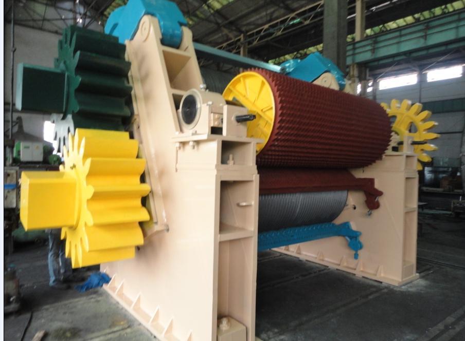
3 HYMECH-2 ROLLER MILL 3

4 HYMECH DESIGN AND MANUFACTURED BY HMC TAXILA 4
5 ABSTRACT Hy Mech is a 02 roller cane crushing mill, indigenously developed by HMC, Taxila, Pakistan, to extract more juice with reduced power consumption and maintenance cost/time. Initially HMC has developed three models, 42 /45 X /50 X /55 X 106 5
6 Performance of these mills are much better than conventional 03 roller mills and is comparable to any internationally developed 02 roller mill, its features are unique, different then other 02 roller mills available in market. Main features are following, It is two roller mills w/o trash plate. Re absorbtion is controlled by decompression chute Top roller is hydraulically loaded. Top roller has lotus arrangement. 6
7 Bottom roller has more surface and drainage area than top roller. Mill is driven by bottom roller. 7
8 OUTLINES In the workshop I will talk more about conceptual and design aspects of Hy-Mech. Following are topics to be discussed, 1- Comparison of 2 and 3 roller mills. Reabsorption of juice. Power consumption. More wear tear in three roller mills. Mill setting. 8
9 2- Special features of Hy-Mech. In Pakistan Importance of hydraulically loaded top roller. Juice drainage from top roller through lotus arrangement v/s Macherate grooves. Unique concept of bigger bottom roller. Mill driven by bottom roller 3- Technical requirements to install Hy-Mech. 4- Performance 5- Problems faced and improvements. 9
10 1) COMPARISON OF 2 AND 3 ROLLER MILLS: A. REABSORPTION OF JUICE The extraction of juice in 2 roller mill is better than 3 roller mill; it is mainly due to better control on re absorption of juice. In the 3 roller mill when cane blanket travels over a trash plate it is subjected to a heavy pressure, it reaches to peak value just before discharge work opening and after that pressure again releases. 10
11 The huge pressure difference before and after discharge opening causes juice particles to jump at a high speed from high pressure zone to low pressure zone, this juice is again absorbed in bagasse at discharge side and is called re absorption. It is not possible in 3 roller mill to fully control it due to geometry of these mills. 11
12 REABSORPTION OF JUICE IN 4-ROLLER MILL 12
13 In 2 roller mills re absorption is controlled by creating a pressure zone after discharge work opening. This pressure is gradually released in a device called gradual decompression chute. No pressure difference is created, juice cannot jump into pressure zone and ultimately it is drained from no pressure areas, i.e. bottom roller, top roller, under feeder, mecharte grooves, and lotus arrangement. 13
14 14
15 Power consumption in 2 roller mills is about 30% less than in 3 roller mills, it is due to less moving parts and no trash plate. ( trash plate consume about 25% of total load). 15
16 3- ROLLER MILL 2- ROLLER MILL No. OF ROLLERS No. OF CROWN PINIONS TRASH PLATE YES NO No. OF BEARINGS UNDER LOAD TAIL BAR LIFT YES NO 16
17 Good mill settings are essential to take good performance from conventional mills, however it is a difficult job; it is always based on detail calculations and experience of operational staff. Unfortunately, a general operational staff has not enough knowledge to calculate it and usually we face problems like poor performance, feeding/choking, more wear and tear problems etc. 17
18 In conventional mills there are at least 6 openings (feed, discharge, tip, center, heel and juice gape) which are calculated and in addition trash plate profile is also drawn. 18
19 MILL SETTING IN 3 ROLLER MILLS 19
20 In comparison to this there are only three opening to be calculated for 2-roller mills (rollers opening, decompression chute inlet & outlet openings). 20
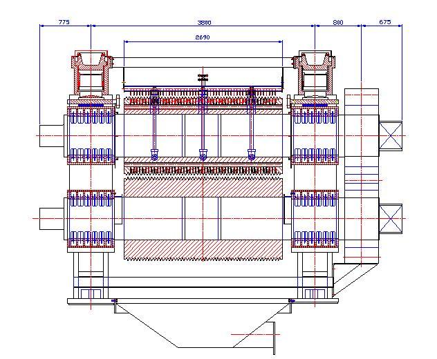
21 MILL SETTING IN HYMECH 21

22 22
23 TOP ROLLER HYDRAULICALLY LOADED Top roller of HYMECH is hydraulically loaded; it keeps constant pressure on cane blanket, irrespective of cane flow, top roller take lift freely under hydraulic load. This arrangement also safeguard mill against any foreign metal piece. 23
24 In Pakistan this system is essential due to following reasons. i. Lot of variation in cane crushing due to cane supply. ii. Variation in cane feeding due to manual loading and no automation on cane feeding. iii. There is frequent variation in donnely chute level, causing variation in performance. iv. If there is no flexible arrangement of inserting pressure on top roller, the extraction will drop with low crushing rate and at higher crushing rate wear/tear, power 24 consumption and re absorption will increase.
25 iv. Because of poor metallurgy used by some vendors usually broken pieces of leveler, cutter knives, shredder hammer, nut and bolts reaches mill they will damage rollers more seriously even a major accident may take place if there is no hydraulic system on top roller. 25
26 26
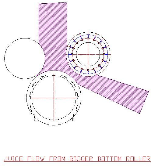
27 BIGGER BOTTOM ROLLER: We have already discussed decompression chute, kindly note that this chute only control the reabsorption of juice it does not eliminate the root causes of re absorption. The root causes of re absorption are more extraction of juice with less juice drainage area and time. We have focused on these phenomena and provided more surfaces and drainage area in the Hy Mech, then the same capacity 02 roller mills available in the market. The cane blanket thickness and linear speeds are reduced automatically. 27
28 So we are able to put double check on re absorption. It is controlled at start of pipe as well as at end of pipe. Specially we increased the surface and drainage area of bottom roller and adapted a unique concept that bottom roller is bigger than top roller. It is based on the idea that juice flows by gravity downward, more surface and drainage area at bottom roller drains juice more quickly. 28
29 29


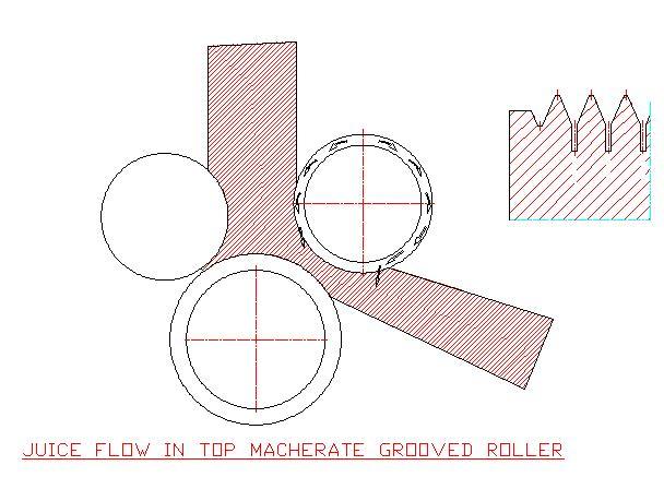
30 Juice drainage area is increased by cutting deep macherate grooves 85 mm deep, in conventional mills it is about 35 mm deep only. CONVENTIONAL MECHARATE GROOVE HYMECH MECHARATE GROOVE 30
31 TOP ROLLER LOTUS TYPE There are two techniques to drain juice from top roller. Lotus roller Macherate grooves The advantages of macherate grooves in top roller are very debatable as there are chances of re absorption of juice through macherate grooves more over they also reduce the compaction areas of top roller. 31
32 32

33 Juice drainage from top lotus roller is very effective and no chances of re absorption. 33
34 BOTTOM DRIVE In three roller mills, drive is from top roller as it drives other two rollers through pinions; there is no alternate of it as far as 3-roller mills are concerned. However, it has some problems. Top roller takes lift, while gearing output shaft only rotates on its axis. Top roller lift is accommodated in box coupling, however sometime this lift is abnormal and there is excessive wear, tear and breakages in box coupling, tail bars, bearing bolts, foundation bolts, mill bearing etc. 34

35 WEAR TEAR DUE TO TOP ROLLER DRIVE IN 3-ROLLER MILL 35
36 In HYMECH, we drive the mill from bottom roller, so that top roller takes lift freely w/o any lift effect on other components, chances of wear tears are reduced. 36
37 Hy Mech driven by bottom roller 37

38 38
39 CANE PREPARATION INDEX TRASHES % CANE +90 % 3-5 % For mill 45/42 x m For mill 50/46 x m For mill 55/52 x m 39
40 4-5 m above the axis of top roller. Auto level control on Donnelly chute to keep it fill by 2/3 height. 40
41 41
42 42
43 43
44 44
45 45

46 46
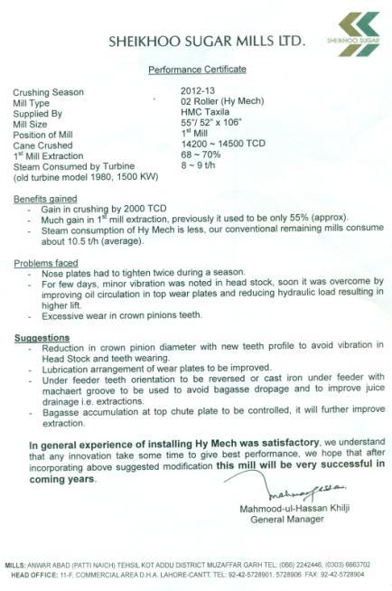
47 It was the 1st experience of HMC to put into operation a newly developed 2 roller mill, it was expected that in 1st go some problems will be faced, however our problems were not of permanent nature, they are minor, can be rectify/improve. We are very confident that in coming years after removing these problems, HYMECH will be very reliable mill both from mechanical and performance point of view. 47
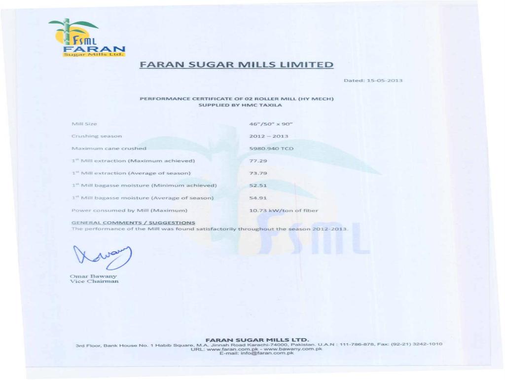
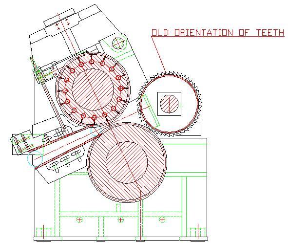
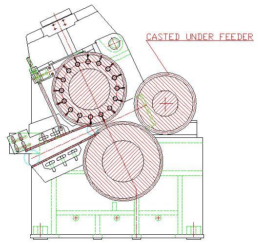
48 1) FABRICATED TOOTH TYPE UNDER FEEDER: It was overlooked by us, while fitting fabricated under feed roller on shaft, that direction of teeth were opposite than the requirements. It started to drop excessive bagasse. We managed it to run by reducing the depth and sharp edges of teeth. For the next crushing seasons we are reversing the teeth direction and also installing cast iron under feed rollers, which we have already tried in Faran sugar mills and it is giving good result. 48

49 49
50 50
51 we are modified pinions for closer mill setting and to take into account wear effect of rollers. In HYMECH adjustment in performance and crushing rate is accomplish by variation in speed and hydraulic load, however there is also provision for rollers opening readjustment due to some special reasons. Our previous arrangement was little difficult, we are modifying it for easy and quick readjustment. 51
52 Bagasse come out through the gape between teeth of roller and noze plate, it is accumulated at top chute pate, from where it is removed by water spray or manually. We are improving it by reducing depth and quantity of chevron grooves on top rollers. Grooving of noze plate will also be modified. we are also doing lot of minor modification for further improvement in performance and working. 52
53 53
54 54