Joint ICTP/IAEA School on Physics and Technology of Fast Reactors Systems 9-20 November 2009 Reprocessing and recycling of fast reactor fuel
|
|
|
- Thomasine Atkinson
- 5 years ago
- Views:
Transcription
1 Joint ICTP/IAEA School on Physics and Technology of Fast Reactors Systems 9-20 November 2009 Reprocessing and recycling of fast reactor fuel Dominique Warin CEA/Nuclear Energy Division Radiochemistry and Processes Department Marcoule France
2 IAEA/ICTP School on Physics and Technology of Fast Reactor Systems Reprocessing and recycling of fast reactor fuel Dominique Warin Radiochemistry and Processes Department Marcoule, France


3 The nuclear fuel cycle REACTOR Spent Fuel Fuel Fabrication Enrichissement Uranium de de Enrichment l'uranium UF 6 Mining and Milling


4 Spent fuel management : what options? - Interim storage - Direct disposal YUCCA MOUNTAIN, NEVADA - Process and recycle MOX fuel
5 The nuclear fuel cycle REACTOR Spent Fuel Fuel Fabrication Enrichissement Uranium de de Enrichment l'uranium UF 6 Mining and Milling a dangerous waste, & an asset
6 About risks Source: IRSN barometer 2006 Level of risk Confidence into government for telling the truth Confidence into the government for solving the issue Nuclear waste

7 Nuclear acceptance : credibility and competence


8 The French Act of December 1991, for 15 years Waste management in France: which goals? Goal 1 research : to reduce the overall radwaste quantity by solutions that would allow partitioning and transmutation of long lived radionuclides present in HL LL nuclear waste Goal 2 research : to study the feasibility of reversible or irreversible repository in deep geological formations Positive results of Underground Laboratory: Dossier Argile 2005 : clay in Meuse/Haute Marne site Galerie Goal 3 research : to study conditioning processes and feasibility of long term storage, above-grade or below-grade Sub surface long term storage demonstration gallery constructed at CEA-Marcoule ; long term storage demonstration containers (scale 1) Deadline set in law : 2006
9 The main results of P and T research programs New possibilities, continuous progress : Extraction molecules have been developed at lab scale, and pre industrial demonstrations have proved successful : industrial partitioning is feasible Transmutation of Fission Products (I, Cs, Tc) is either not feasible or unrealistic MAs transmutation is unrealistic in PWR Transmutation experiments, at pin scale, have been carried out for americium and neptunium in a power reactor, such as Phénix, which demonstrates the feasibility of their transmutation in SFR Feasibility of transmutation in ADS is not obtained today, and research must going on Realistic scenario : Transmutation can be carried out only with the new generation of fast neutron reactors, as a contribution to sustainable nuclear energy by homogeneous or heterogeneous mode
 and to ease the conditions of a deep geological repository Natural uranium ore Time Main radiotoxicity contributors : 1) Pu 2) MA 3) LLFPs")
10 Relative radiotoxicity Recycling strategy Aim of recycling : to minimize the quantity and radiotoxicity of long lived nuclear waste Potential gain : to reduce at hundreds years the life time of future waste (compared to the level of initial U nat ) and to ease the conditions of a deep geological repository Natural uranium ore Time Main radiotoxicity contributors : 1) Pu 2) MA 3) LLFPs (years) Fundamental hypothesis : closed cycle, GEN IV fast neutron reactor implemented at mid or long term (whatever the cooling : Na, gaz, ) Reference strategy : PWRs: Pu management by multi recycling GEN IV SFR or GFR: full actinides recycling, beginning 2040 Option of the «double strata» PWRs Accelerator Driven Systems Demonstrations of scientific and technical feasibilities, FP MA + FP Spent fuel (Pu + MA + FP) before pre industrial development of recycling
11 Recycling strategy : systems evolution (Fuel cycle) The new requirements : Save resource Minimize environment impact (waste nocivity) Increase resistance vs proliferation risks New purposes, other than electricity (heat, H2, dessalinization) And obviously : safety, costs (Reactors)

12 Save resource : Uranium ore Ore: kg U/ ton 235 U : 0.7 % 238 U : 99.3 % Average earth crout :few grams U/ ton Seawater: few mg U / ton water

13 Save resource : Uranium resources

14 Uranium world production and consumption 2005 records : tons produced tons needed


15 The Evolution of Nuclear Power to fast systems First Reactors Current Reactors Advanced Reactors Future Systems Generation I UNGG CHOOZ Generation II REP 900 REP 1300 N4 Generation III EPR? Generation IV
16 Transition scenarios between generations in France Major role of LWRs in the 21 st century Current PWRs (Gen II ): life time extension (> 40 years) Gen III/III+ PWRs : current PWRs replacement around 2015 (EPR) Operation during 21 st century A transition scenario between LWRs and Fast Neutrons Systems Reactors Current Fleet Life time extension EPR Gen IV Source : EDF, ENC 2002 Cycle U (U dep, URT) Pu (MOX recycling) Cycle Gen IV Recycling Gen IV M.A. + F.P. ---> glasses Disposal M.A. ---> glasses or recycling F.P. ---> glasses
17 Nuclear acceptance and a responsible management of spent fuel and waste A responsible management of nuclear spent fuel : Recycles 96% of spent fuel materials Saves 30% of natural resources Costs less than 6% of the kwh total cost Reduces by 5% the amount of wastes Reduces by 10% the waste radio toxicity Adapted technologies allow a safe conditioning of wastes to guarantee their long term confinement and stability, during dozens of thousands of years Recycling, such as implemented today in France, GB or Japan, gives time and opens a large range of options for the satisfactory management of nuclear wastes. more sustainable policy better public acceptance
 Fission Products (4%) Plutonium (1%).")
18 The spent nuclear fuel 235U=0.9% Uranium (95%) Fission Products (4%) Plutonium (1%). Minor Actinides (0.1%) Average Content Fissile isotopes = 75%
19 UOX Nuclear spent fuel 1 3 H Li 11 Na ORIGINE DES ELEMENTS CHIMIQUES DANS LE COMBUSTIBLE IRRADIE 4 Be 12 Mg (UOX : 3,5 % 235 U ; 33 GWj.t -1 ) U : 955 kg.t -1 Pu : 9,6 kg.t -1 AM : 0,8 kg.t -1 PF : 34 kg.t -1 5 B 13 Al 6 C 14 Si 7 N 15 P 8 O 16 S 9 F 17 Cl 2 He 10 Ne 18 A 19 K 20 Ca 21 Sc 22 Ti 23 V 24 Cr 25 Mn 26 Fe 27 Co 28 Ni 29 Cu 30 Zn 31 Ga 32 Ge 33 As 34 Se 35 Br 36 Kr 37 Rb 38 Sr 39 Y 40 Zr 41 Nb 42 Mo 43 Tc 44 Ru 45 Rh 46 Pd 47 Ag 48 Cd 49 In 50 Sn 51 Sb 52 Te 53 I 54 Xe 55 Cs 56 Ba Ln 72 Hf 73 Ta 74 W 75 Re 76 Os 77 Ir 78 Pt 79 Au 80 Hg 81 Tl 82 Pb 83 Bi 84 Po 85 At 86 Rn 87 Fr 88 Ra An 104 Rf 105 Db 106 Sg 107 Bh 108 Hs 109 Mt 110 Uun LANTHANIDES 57 La 58 Ce 59 Pr 60 Nd 61 Pm 62 Sm 63 Eu 64 Gd 65 Tb 66 Dy 67 Ho 68 Er 69 Tm 70 Yb 71 Lu ACTINIDES 89 Ac 90 Th 91 Pa 92 U 93 Np 94 Pu 95 Am 96 Cm 97 Bk 98 Cf 99 Es 100 Fm 101 Md 102 No 103 Lr NOYAUX LOURDS PRODUITS DE FISSION PRODUITS D ACTIVATION PRODUITS DE FISSION ET D ACTIVATION
20 UOX and MOX spent fuels : typical content UOX (45 GW/t) MOX (45 GWj/t) URANIUM 940 kg 890 kg PLUTONIUM 11 kg 56 kg FISSION PRODUCTS 48 kg 48 kg MINOR ACTINIDES 1 kg 6 kg (for 1 tonne initial HM)
21 Spent fuel : radioactive content AVERAGE BU ~ MWd/t 6 months after unloading : assembly : TBq (18 kw) 3 years after : TBq ( 3 kw) FISSION PRODUCTS β - mainly very diverse radioactive periods CAPTURE PRODUCTS Actinides (Pu 1 %, Minor Actinides ~ 0.4 %) α and long radioactive periods ACTIVATION PRODUCTS structure metallic materials (Zr isotops) or fuel initial contaminants ( 14 C from 13 N or 17 O traces in initial oxide) (36Cl from 35Cl traces in initial oxide)
22 Radiotoxicity of LWR-UOX Spent Fuel Radiotoxicity Inventory (Sv/TWhe) Total UOX Fuel Pu Minor Actinides Fission Products U Activation Products Time (years) Ingestion Doses Coefficients from ICRP72
23 Reprocessing : the principle URANIUM PLUTONIUM SPENT FUEL REPROCESSING FISSION PRODUCTS & MINOR ACTINIDES
24 Recycling Uranium and Plutonium (UOX) (MOX) REACTORS Spent fuel Fuel Manufacturing Plutonium Reprocessing Uranium Enrichment Uranium Mining & Milling Uranium WASTE (FPs & MAs)

25 Closing the Fuel cycle an industrial reality The exemple of the french situation : Mines Natural Uranium Chemistry Enrichment 58 PWRs 400 TWh annually ~ 78 % of french electric production Ultimate Wasre Disposal Uranium recyclable Plutonium Recycling : MOX Fuel fabrication Enriched Uranium Fuel Fabric. Fuel processing : more than 25 years of experience 1100 t HM /yr of spent fuel discharged from the French PWRs 850 t HM /yr of domestic spent fuel reprocessed + foreign Spent Fuel Reprocessing Reactors & Services Until now: ~ t HM spent fuel reprocessed and more than 1500 t HM MOX fuel recycled Front-End Sector Reactors & Services Sector Back-End Sector

26 Fuel Reprocessing and recycling LA HAGUE UP2-UP3 PLANT >21000 t processed MARCOULE MELOX PLANT >1000t manufactured
27 La Hague Repocessing plants History : UP2, 400t/y, UNGG Fuel : UP2/HAO, 400 t/y LWR Fuel , : UP3, 800 t/y, LWR Fuel , : UP2/800, 800 t/y, LWR Fuel


28 La Hague plants production (treated fuels)
29 UP2/HAO Feedback Many difficulties at the beginning of the operation Bad estimation of hard-linked to the reprocessing of LWR fuel Technological gap from the UNGG to the LWR spent fuel French decision to launch a major R & D plan for the UP3 process From the head end process to the waste conditionning Clean Plant Continuous dissolution The increasing of the Burn Up of the LWR fuel The LWR MOX Spent Fuel Treatment

30 Closing the Fuel cycle an industrial reality

31 Closing the Fuel cycle an industrial reality
32 Exemple of La Hague cooling pool Dimensions : -L: 50 m - l : 16 m -P: 9 m (about 7200 m 3 water) Storage capacity : baskets, each bearing :. 9 PWR assemblies. or 16 BWR assemblies ( 4000 t, 200 reactor.years)

33 UP3 Dissolution Line Mock-Up Iodine desorber Shearing machine Nozzles rinsing vessels -Nitricacid -Water Wheel dissolver Hulls rinsing vessel Filling drums hulls and tips
 Cladding shear ram Shearing chamber Deflectors Nozzles shear")
34 Mechanical shearing machine Operating mock-up of UP3 shearing tools Compactor rams Shear Pack Hopper for Nozzles Shear pack Hopper for pieces of fuel (dissolver charge chute) Cladding shear ram Shearing chamber Deflectors Nozzles shear pack


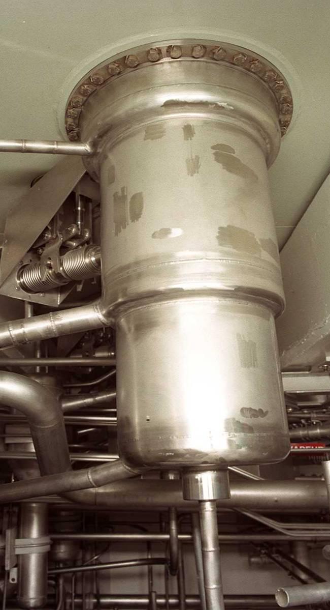
35 Continuous Wheel Dissolver UP3 Dissolver vessels

36 UP3 and UP2-800/R4 : Pulsed columns

37 UP2-800/R4 : Centrifugal contactors


38 La Hague Vitrification line CSDV
39 Feedback of UP3 and UP2-800 operation At the Beginning : UOX from 10 to 30 GWd/tHM Today : UOX 45 GWd/tHM Tomorrow : 60 GWd/tHM And also : 72,6 t of LWR MOX irradiated from 30 to 53 MWd/HM in industrial conditions (Demonstration Campaigns) Feedback after 20 years of UP3 and UP2-800 operation (more than tons of LWR fuels reprocessed) - Robust PUREX Process, large capacity, safety, - Flexible Plants


40 Pu Recycling with MOX fuels : the MELOX plant


41 Key advantages of the advanced MELOX high-throughput process UO 2 Recycling PuO 2 material UO 2 Primary blend Scrap UO 2 PuO 2 UO 2 Primary blend Primary blend Secondary blend 1 Preparation of primary blend 2 Preparation of secondary blend Powder blending is the key to the MELOX process. The MELOX process allows an on-line recycling of almost all scrap. More than 35 years of PWR and BWR operating experience have demonstrated the high quality of MOX fuel fabricated by the AREVA group. MOX fuel behavior in the reactor is similar to UO 2 fuel in normal and off-normal conditions. The performance and reliability of the MELOX process are recognized worldwide

42 MELOX Fuel fabrication process One MOX fuel assembly contains enough energy to supply a city of 100,000 with electricity for an entire year
 Triple certification ISO 9001 / 14001 (Quality / Environnement) OHSAS 18001 (Health and Safety) ISO 9001 / 14001 (Quality / Environnement) French Quality")
43 Total Quality Management at MELOX Continuous improvement to achieve customer satisfaction Constant attention to successful environmental integration French Quality Award in ISO (Security and information system) Triple certification ISO 9001 / (Quality / Environnement) OHSAS (Health and Safety) ISO 9001 / (Quality / Environnement) French Quality Award Regional Quality Award ISO (Environment) ISO 9002 (Quality)


44 MELOX Plant safety Prevention and control of nuclear materials dispersion and external exposure are based on: A confinement system using three barriers and dynamic containment (negative air pressure) Second barrier: The workshop Third barrier: The building First barrier: The glove box The static containment High level of plant automation


45 MELOX Plant design Seismic support Major risk prevention has been integrated into facility design Fire Criticality Seismic measurements Thermal risks Thermocouple Fire door Neutron radiation detector CO 2 fire extinguisher
46 MELOX: a continuous and effective system of safeguards National and international organizations (Euratom, IAEA) monitor nuclear materials at AREVA MOX fabrication plants. Euratom worked with the French regulatory authorities and the plant operator during the MELOX design phase to develop the system of safeguards with the objective of Continuous Inventory Verification This system is specific to the plant characteristics: Control of inputs/outputs Independent, automatic measurements Control of the annual inventory of nuclear materials Sample analysis This system complies with IAEA requirements
 MELOX impact 0.000014 msv Dose from a lung X-ray 0.3 msv Dose from a Paris / New York flight 0.")
47 Radiological impact of the MELOX plant In year 2008, the impact of liquids and gaseous radioactive effluents of MELOX plant is about msv Background radiation In France 2.4 msv Old regulatory limit 5 msv Dose to the public new regulatory limit 1 msv (since April 2002) MELOX impact msv Dose from a lung X-ray 0.3 msv Dose from a Paris / New York flight 0.02 msv Maximum effluents impact allowed by the decree: msv per year


48 Reprocessing of SFR MOX FUEL : French experience RAPSODIE Reactor 40 MWTh PHENIX Reactor 600 MWth / 250 MWe
 : - Capacity : 1 kg/d - Burn Up : 40 to 120 GWd/t mixed oxide - Cooling time : from 6 months to 2 years - ~1 t of MOX SFR spent fuel")
49 Reprocessing of SFR MOX FUEL : French experience AT1 La Hague Facility ( ) First French facility for the reprocessing of SFR MOX FUEL (from Rapsodie and Phénix reactors) : - Capacity : 1 kg/d - Burn Up : 40 to 120 GWd/t mixed oxide - Cooling time : from 6 months to 2 years - ~1 t of MOX SFR spent fuel treated
50 Reprocessing of SFR MOX FUEL : French experience UP2-400 La Hague Facility ( ) Reprocessing of ~11 t of PHENIX Fuel - Burn Up : 20 to 90 GWd/t mixed oxide - Cooling time : from 16 months to 4 years Batch dissolution and extraction of U and Pu by dilution in UNGG fuel dissolution
 KNK and PHENIX Spent fuel - ~ 7 t of MOX SFR Spent fuel - Burn Up : 60 to 103 GWd/t mixed oxide - Cooling time : from 3 to 10")
51 Reprocessing of SFR MOX fuel : French experience Marcoule Pilot Facility - TOP Facility ( ) RAPSODIE, KNK and PHENIX Spent fuel - ~ 8 t of MOX SFR Spent fuel - Burn Up : 35 to 105 GWd/t mixed oxide - Cooling time : from 10 to 50 months - TOR Facility ( ) KNK and PHENIX Spent fuel - ~ 7 t of MOX SFR Spent fuel - Burn Up : 60 to 103 GWd/t mixed oxide - Cooling time : from 3 to 10 years
O2 (U,Pu)O2 235 U: 3-4,5% Pu: 3-8,5% Pu: 13-20% Metallic Materials Assembly 270 pins 200-300 pins Cladding Zircaloy Zircaloy Stainless steel Solubility Criticality Corrosion Fe, Cr,.")
52 What characterize the SFR MOX Fuel at the reprocessing Fuel Characteristics LWR MOX RNR UOX MOX Composition before. irr. UO2 enrichi (U,Pu)O2 (U,Pu)O2 235 U: 3-4,5% Pu: 3-8,5% Pu: 13-20% Metallic Materials Assembly 270 pins pins Cladding Zircaloy Zircaloy Stainless steel Solubility Criticality Corrosion Fe, Cr,... Others materials Nozzles, grids, SNP, nozzles, wrapper, spacewire, Technology Ø pins (mm) 11 à à 12 6 à 8 LWR SFR Irradiation BU (MWd/t) 33000/ / / Average temperature ( C) C) C 1700 Thermal power Cooling 1 year (KW) Composition after irr. Plutonium Minors Act. 0,03-0,1 0,55 0,5 FP 3, Nobles metals 0,4 0,9 2-3 Pu-PF compounds Glasses Incorporation
53 The french Act of June 2006, up to 2015 and 2020 Key-points for waste management, and future R and D : A national plan on radioactive materials and radioactive waste management (up-grading by Parliament every three years) A program on R & D with a time schedule to implement this plan A secured financing of radioactive waste management and R & D (dedicated fund) A step by step program of HLLL waste management, including the 3 complementary solutions : Geological disposal for the final HL waste (dossier and Parliament decision in 2015, operation in 2025) ; existing wastes will be disposed Intermediate storage for industrial flexibility MA Recycling : - R & D in the framework of Gen IV Systems; international framework - interest (as consequences on the geological repository) to be proved with a cost/benefit detailed analysis by decision : demo by 2020 ; industrialization by 2040