Japanese Strategy for CO Reduction
|
|
|
- Alexander Garrett
- 5 years ago
- Views:
Transcription
1
2 Contents Japanese Strategy for CO 2 Reduction Oxy-firing Studies in Japan Study of 1000MW Oxy-firing Super-Critical Unit Japan-Australia Oxy-firing Project Conclusion
3 Contents Japanese Strategy for CO 2 Reduction Oxy-firing Studies in Japan Study of 1000MW Oxy-firing Super-Critical Unit Japan-Australia Oxy-firing Project Conclusion
4 Trend of World CO2 Emission CO2 emission 100 million ton LNG Oil Coal For power plant For primary material For transportation device For power plant For iron-making process CO 2 emission in the world CO 2 reduction is prime task for global warming and is not depend on the place to recover CO 2. By IEA/World Energy Outlook 2000

5 Japanese Coal Import From METI Home Page
6 KYOTO Protocol Japan must reduce GHG at 6% From METI Home Page
7 Use of Coal
8 New Coal Policy in Japan Japan s new coal policy towards 2030 called Clean Coal Cycle (C3) Initiative is presented and launched. To promote the development of innovative CCT towards the realization of zero-emission utilization is described in C3 Initiative.
9 From METI Home Page
10 Field : : Promote the development/demonstration/dissemination of CCT CH4 CO2 H2 Hydrogen Power From METI Home Page FC FC FC FC Chemicals FC
11 Field CCT 1. Promote the development of innovative CCT *F/S of Advanced Gasification *Oxy-fuel to existing boiler with Australia *IGCC, IGFC, HyPr-RING 2. Demonstrate diversified CCT models *F/S of co-production with gasification *F/S of CTL/H 2 from coal/biomass/plastics gasification
12 From METI Home Page CCT Spreading Energy Sector in Japan(2030) FC Vehicle FC Biomass Waste Coal Gasification STEEL Hydrogen Station CHEMICAL, etc Co-production SCOPE21 HyPr-RING FC Power Station POWER Iron Works USC IGCC IGFC FC CO2 Capture CO2 Sequestration Coal UBC(Upgrading Brown Coal)
13 Contents Japanese Strategy for CO 2 Reduction Oxy-firing Studies in Japan Study of 1000MW Oxy-firing Super-Critical Unit Japan-Australia Oxy-firing Project Conclusion
14 . Oxy-firing Studies in Japan
15 CO 2 Reduction Technology from Coal Fired Power Plant Newly-installed plant High efficiency IGCC 700 class USC Existing plant High efficiency Switching fuel Positive CO 2 recovery Oxy-firing Chemical absorption
16 Oxy-fuel Combustion System Air P.C. Boiler ASU Flue gas recycle
17 Coal Combustion under CO 2 Atmosphere Item Combustion with air Combustion with oxygen Windbox O2 N2 CO2 % H2O Small Others NOx SO2 Flue gas O2 N2 CO2 H2O Others NOx SO2 NOx SO2 Wet base
18 Calendar of Japanese Oxy-firing Study Ignition and lame propagation under zero gravity Combustion characteristics In furnace desulfurization test Combustion simulation Boiler system study 1000MW design study Operation characteristics Dynamic simulation Callide A project
19 Ignition Characteristics Small gravity test Device Free drop chamber Gravity g 10seconds Gas sampling cylinder Band pass filter High speed camera (temperature observation) Time Sequence Combustion chamber Capsule drop A/D converter Computer 8mm VTR Pressure transducer Coal dispersion gas Solenoid valve Pulverized coal particle Device Battery Timer Relay +7sec. Ignition Observation +10sec. Test procedure

20 Ignition Characteristics 20msec 40msec 60msec CO 2
21 Experimental system to simulate O2/CO2 coal combustion School of Engineering Tokyo Institute of Technology
22 Summary of CR * values for O 2 /CO 2 coal combustion λ (oxygen-fuel stoichiometric ratio) From Prof. Okazaki Drastic NOx Reduction (NOx: mainly due to Fuel-NOx) (Drastic decrease of Conversion Ratio from Fuel-N to NOx) NO concentration in exhaust gas 1130 ppm 1710 ppm 1490 ppm CR * Ratio of CR * to that of air combustion 17 % 25 % 26 % (1/6) 1/4 1/4 CR *: conversion ratio from fuel-n to exhausted NO Ratio of CR * to that of air combustion = CR * in O 2 /CO 2 coal combustion CR * in conventional coal combustion in air School of Engineering Tokyo Institute of Technology
23 Drastic Reduction of CR* (Fuel-N to NOx) by Oxy-firing Base case Conventional O2 : 21% H.R.: 0% From Prof. Okazaki Oxy-fuel O2 : 30% H.R.: 0% Oxy-fuel O2 : 21% H.R.: 0% Oxy-fuel O2 : 15% H.R.: 40% School of Engineering Tokyo Institute of Technology
24 Mechanism of In-furnace Desulfurization From Prof. Okazaki What is in-furnace desulfurization? SO 2 SO 2 A very economical method of SO 2 removal through sorbent (CaCO 3 ) injection into the furnace Desulfurization reaction: CaCO 3 CaO + CO 2 CaO + SO 2 + 1/2O 2 CaSO 4 Coal CaO CaSO 4 decomposition: CaSO 4 CaO + SO 2 + 1/2O 2 CaSO 4 The cause of decrease in desulfurization efficiency at high temperature School of Engineering Tokyo Institute of Technology
25 Local desulfurization efficiency 0.35 Gas recirculation ratio: 0.84 From Prof. Okazaki Removed-S (CaSO 4 ): 0.77 (mol/s) Fuel-S (SO 2 ): 1.0 (mol/s) SO (mol/s) 1.43 (mol/s) Exhausted-S: 0.23 (mol/s) Recycled-S: 1.2 (mol/s) System desulfurization efficiency: h = 77 % Coal property (wt. %, dry) C: 71.1 O: 8.86 H: 4.23 N: 1.76 S: 2.00 Calculation conditions Oxygen-fuel ratio = 1.2, Temperature = 1400 K one pass residence time = 8 s,ca/s = 5, CaCO 3 (10 mm) School of Engineering Tokyo Institute of Technology
26 Enrichment of heat and mass in combustion field From Prof. Okazaki Combustion field Recirculation of heat (enrichment of heat) Recirculation of mass (enrichment of mass) CO 2 Easy and efficient CO 2 separation?recovery NOx Extremely low NOx emission SOx High in -situ desulfurization efficiency Combination of heat and mass recirculation New combustion technology (PCC, AFBC, CFBC, PFBC, IGCC c) Protection of global environment School of Engineering Tokyo Institute of Technology

27 Combustion Test and CO 2 Compression Test Combustion Test Facility Capacity 1.2Mwt Coal 150kg/h Furnace 1.3m 7.5m IHI Test Facility - AIOI
28 Oxy-firing Test Facility Primary Gas Fan Electrical heater LPG Desulfurizing agent bin CO 2 Pulverized coal bin Furnace Gas cooler Pre gas Gas heater cooler Bag filter Stack O 2 tank Induced draft fan Desulfurizing agent bin Steam gas heater O 2 evaporator Gas recirculation fan Water spray cooler Air intake Flow diagram of industrial-scale combustion test facilities


29 Flue Gas (CO 2 ) Liquefied Test Transporting gas for P. C. Furnace Combustion gas GRF Water spray Steam heater Gas cooler Flue gas compressor GAH, G/C Bag filter IDF Stack ( ) Pressure 7 MPa vessel 0 Cooling unit Compressor Flue gas compressor unit Pressure vessel


30 Results of Oxy-firing Test Ignition/combustion characteristics Flame of test facilities Flame temperature Radiation thermometer)
31 Result of Oxy-firing Test Combustion condition Coal : Coal A Coal feed rate : 100 kg/h Flue gas oxygen : 3.5% Wind box oxygen : 30% (O 2 /RFG combustion) Pure oxygen flow rate : 20 Nm 3 /h (O 2 /RFG combustion) Burner type (O 2 /RFG combustion) TYPE- : Pure oxygen supply from the center of the burner TYPE- : Pure oxygen swirly supply from the center of the burner Unburned carbon in fly ash (%) O2/RFG, TYPE- burner O2/RFG, TYPE- burner Air combustion NOx conversion ratio (%) O2/RFG, TYPE- burner O2/RFG, TYPE- burner" Air combustion Excess oxygen ratio at the burner ( ) Excess oxygen ratio at the burner ( )
32 Result of Desulfurization Test Combustion conditions Coal : Coal A, B Flue gas Oxygen : 3.5% Coal feed rate : 100 kg/h Wind box oxygen : 30% Pure oxygen flow rate : 20Nm 3 /h Desulfurizing agent: CaCO Air combustion ; Coal A O2/RFG combustion ; Coal A O2/RFG combustion ; Coal B 100 Others Deposit on f urnace Fly ash O2/RFG Combustion Desulfurization rate (%) Desulfurization rate (%) Air Combustion Ca/S mol ratio ( ) Comparison of desulfurization rate Ca/S (-) Sulfur captured in the system
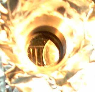
33 Ignition/Combustion Characteristics
34 Contents Japanese Strategy for CO 2 Reduction Oxy-firing Studies in Japan Study of 1000MW Class Oxy-firing Super-Critical Unit Japan-Australia Oxy-firing Project Conclusion
35 Basic Design of 1,000MWe Class Power Plant
36 Boiler Configuration
37 Optimum System Flow
 Oxy-case WB O2 conc.")
38 Furnace Heat Absorption Air-case (21%) Oxy-case WB O2 conc. 25% 30% 35%
39 ASU and Compressors
40 Dynamic Plant Simulation
41 Dynamic Plant Simulation (Note) :Light off :Combustion mode change :Turbine roll :30%L to 60%L :Synchronization :Furnace draft control :Turbine master auto
42 Dynamic Plant Simulation (Note) :Light off :Combustion mode change :Turbine roll :30%L to 60%L :Synchronization :Furnace draft control :Turbine master auto

43 Basic Design
44 Contents Japanese Strategy for CO 2 Reduction Oxy-firing Studies in Japan Study of 1000MW Oxy-firing Super-Critical Unit Japan-Australia Oxy-firing Project Conclusion

45 Japan/Australia Oxy-firing Project Power plant site Site : Queensland, Australia Plant : CS Energy Callide-A No.4 unit Output : 30MWe
46 Japan/Australia Oxy-firing Project Overall Schedule Items FS of Aus./Japan Project Design, conversion, operation of demonstration plant Commercial plant
47 Contents Japanese Strategy for CO 2 Reduction Oxy-firing Studies in Japan Study of 1000MW Oxy-firing Super-Critical Unit Japan-Australia Oxy-firing Project Conclusion
48 Conclusion Oxy-firing one of the simplest ways to reduced CO 2 Many Oxy-firing projects in many places go together hand in hand Acknowledgement: All the tests except done in TIT were funded by NEDO.
49 From Prof. Okazaki FutureGen CO + H2 gasification Fossil Fuel (Coal, Oil..) O2/CO2 Combustion Renewable Energy (Wind, PV..) shift reaction (Future) steam reforming CO2 + HH22 exergy enhancement of low quality waste heat Air-blown Combustion Electricity H2 + O2 H2O Hydrogen Energy System with Exergy Regeneretion (Fuel Cell ) CO2 Recovery CO2 Separation and Recovery (MEA, KS-1..) CO2 Sequestration (Ocean, Geological..) Integration of Coal, Hydrogen and CO2 Sequestration School of Engineering Tokyo Institute of Technology