Concurrent Session B: LID Design Specifications (Chapter 4 in Draft Manual)
|
|
|
- Ernest Miles
- 5 years ago
- Views:
Transcription


1 Concurrent Session B: LID Design Specifications (Chapter 4 in Draft Manual)
2 Should vs. Must In Chapter 4, should means should, and must means must.
3 Poorly Drained Soils Well-Drained Soils Flat Terrain High Groundwater Site Conditions Tidally Influenced Drainage Systems Pollutants of Concern: sediment, phosphorus, nitrogen, and bacteria
4 Treatment Capability Coastal Zone (1/2 mile from receiving water): ½ inch of runoff from site or 1 inch from impervious cover Shellfish Beds (1,000 feet from shellfish bed): 1 ½ inches retained on site. Water Quality Treatment Wet ponds: ½ of runoff Dry ponds: 1 of runoff Infiltration/LID: 1 of runoff from impervious cover Water Quantity Control 2-year and 10-year post- to pre- peak flow

5 Table

6 Table (continued)
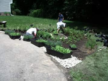
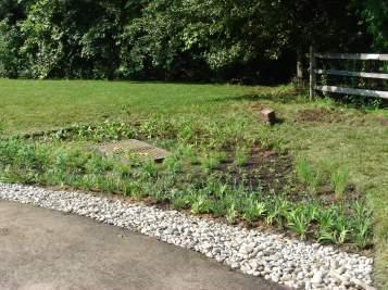
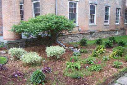
7 4.2 Bioretention


8 Bioretention Standard Design media 60% credit for the volume captured Oversizing allowed to meet full criteria

9 Bioretention Enhanced Design (1) 24 media, no underdrain 100% credit for the volume captured Must infiltrate within 72 hours

10 Bioretention Enhanced Design (2) 24 media, underdrain 100% credit for the volume captured Sump must infiltrate within 72 hours

11 Bioretention Feasibility Criteria Works for all soil types and most site conditions Underdrain required if infiltration rate is less than 0.3 /hour No irrigation or baseflow Liner required for hotspots

12 Conveyance Criteria and Pretreatment Conveyance: Off-line vs. On-line On-line requires overflow device Pretreatment Required Pretreatment Cell Grass Filter Strips Stone Diaphragm Etc.
13 Bioretention Design Criteria Maximum ponding depth 18 with 3:1 side slopes Minimum filter depth 24 for enhanced designs 18 for standard designs Infiltration designs Volume must infiltrate within 72 hours
14 Bioretention Design Criteria Filter Media Specifications 80%-90% sand (at least 75% is classified as coarse or very coarse sand) 10%-20% soil fines (silt and clay; maximum 10% clay) 3%-5% organic matter (leaf compost) P concentrations between 5 and 15 mg/kg (Mehlich I) or 18 and 40 mg/kg (Mehlich III)

15 Bioretention Design Criteria Surface Cover Options Mulch and perennial vegetation Turf Stone with perennial vegetation
16 Bioretention Design Criteria Sizing Equation Where: Sv practice = total storage volume of practice (ft 3 ) SA bottom = bottom surface area of practice (ft 2 ) d media = depth of the filter media (ft) η media = effective porosity of the filter media (typically 0.25) d gravel = depth of the underdrain and underground storage gravel layer (ft) η gravel = effective porosity of the gravel layer (typically 0.4) SA average = the average surface area of the practice (ft 2 ) SAbottom + SAtop SAaverage = 2 = the maximum ponding depth of the practice (ft). d ponding bottom ( d η ) + ( d )] + ( SA d ) Sv = SA η [ media media gravel gravel average ponding
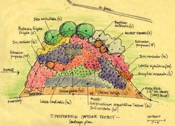
17 Bioretention Landscaping Criteria
18 Questions?

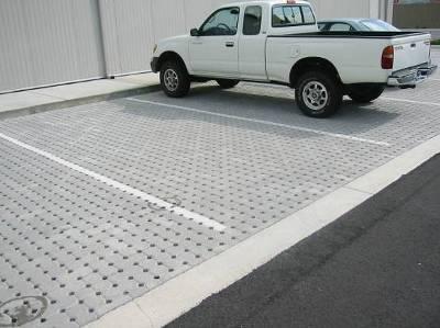
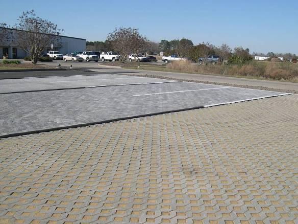
19 4.3 Permeable Pavement


20 Permeable Pavers Asphalt Permeable Pavement Pervious Concrete Porous Asphalt
21 Permeable Pavement Source: Hunt and Collins, 2008


22 Permeable Pavement Versions Standard Enhanced with Underdrain Enhanced without Underdrain
23 Permeable Pavement Feasibility Criteria Ratio of external contributing impervious surface to permeable pavement is 5:1 CDA should be impervious Underdrain required if infiltration rate is less than 0.3 /hour
24 Conveyance Criteria and Pretreatment Large storm events must be managed Overdrains/overflow inlets Extra storage depth Underground detention Pretreatment not needed if CDA is 100% impervious
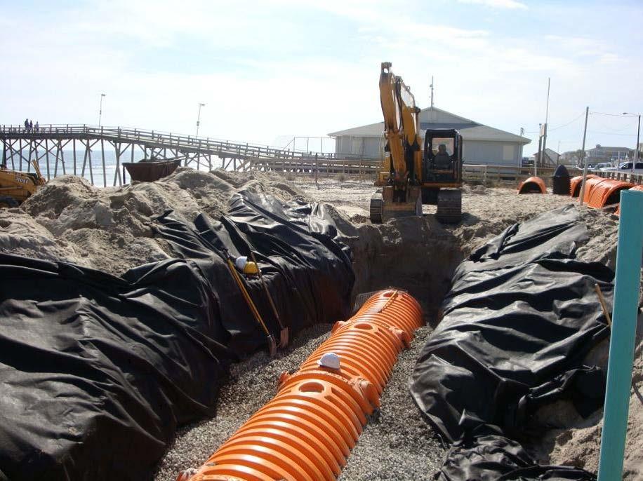
25 Permeable Pavement Design Criteria Specifications for each layer/element Reservoir Layer No. 57 or No. 2 stone; sized for design storm Underdrains PVC with 3/8 inch perforations; drain practice in hours Infiltration Sump No. 57 or No. 2 stone; must drain in hours
26 Permeable Pavement Design Criteria Structural Design AASHTO Guide for Design of Pavement Structures (1993) AASHTO Supplement to the Guide for Design of Pavement Structures (1998) Hydraulic Design Design volume
27 Permeable Pavement Design Criteria Equation 4.3-1: d p = Depth of the reservoir layer (or the depth of the infiltration sump, for enhanced designs with underdrains) (ft) DA = Total contributing drainage area, including the permeable pavement surface (sf.) A p = Permeable pavement surface area (ft 2 ) P = The rainfall depth for the SWRv or other design storm (ft) Rv I = Runoff coefficient for impervious cover (0.95) i = The field-verified infiltration rate for the subgrade soils (ft./day). If an impermeable liner is used in the design then i = 0. t f = The time to fill the reservoir layer (day) assume 2 hours or day η r = The effective porosity for the reservoir layer (0.35) d p = P RvI Ap DA η r i t 2 f
28 Permeable Pavement Design Criteria Equation 4.3-2: For enhanced design only t d = Time to drain (days) (must be < 2.0) d p = Depth of the reservoir layer (ft) η r = The effective porosity for the reservoir layer (0.35) i = The field-verified infiltration rate for the subgrade soils (ft./day). If an impermeable liner is used in the design then i = 0 Equation 4.3-3: Sv = Storage Volume of Practice (ft 3 ) Ap = The permeable pavement surface area (ft 2 ) t f = The time to fill the reservoir layer (day) assume 2 hours or day t Sv d = = d p η i 2 r = d p η i r i t 2 ( ) f d + p η r Ap 2
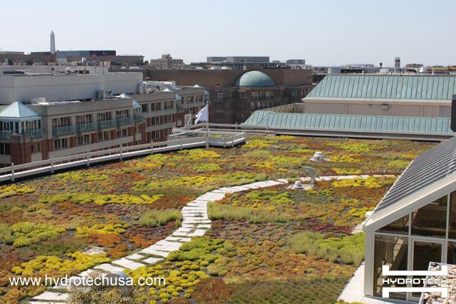
29 Additional Specification Sections Landscaping Criteria Construction Sequence Maintenance Criteria

30 Permeable Pavement Volume Credit Standard Design: 50% credit for volume captured

31 Permeable Pavement Volume Credit Enhanced Design without Underdrain: 100% credit for volume captured
32 Permeable Pavement Volume Credit Enhanced Design with Underdrain: 100% credit for volume captured below underdrain, plus 50% credit for volume captured above underdrain
33 Questions?
34 4.4 Stormwater Infiltration 100% credit for water that infiltrates in 72 hours ½ measured infiltration rate used as safety factor
35 Infiltration Options
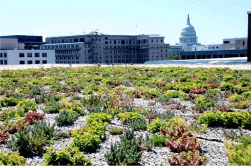
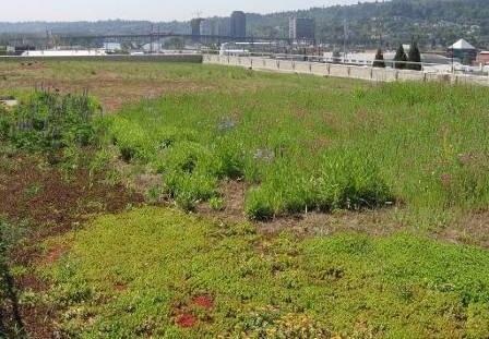
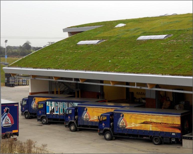
36 4.5 Green Roofs

37 Green Roofs Extensive or Intensive Structural design considerations High installation cost Increased roof longevity Additional urban environmental benefits Major element of compliance at urban development sites

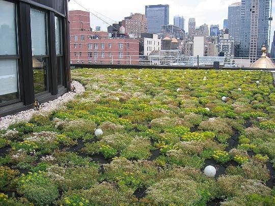
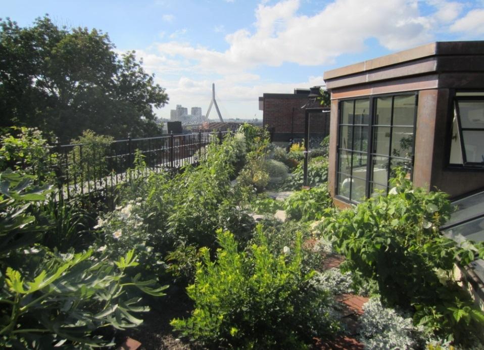
38 Intensive Extensive
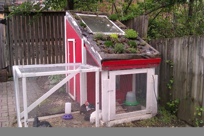
39 Small-Scale
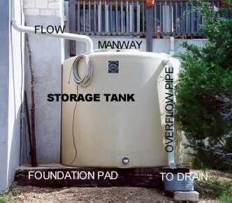
40 Green Roof Feasibility Criteria Structural capacity of roof Roof pitch Setbacks from HVAC, etc. Compliance with building codes
41 Conveyance and Pretreatment Drainage layer and roof drains must safely convey overflows No requirements for pretreatment

42 Green Roof Design Criteria Material specifications for each layer
43 Green Roof Design Criteria Sizing Equation SA [( d η ) ( DL )] Sv Sv = storage volume (ft 3 ) SA = green roof area (ft 2 ) d = media depth (in) (minimum 3 in.) = η 1 = verified media maximum water retention (use 0.15 as a baseline default in the absence of verification data) DL = drainage layer depth (in.) 1 + η 2 12 η 2 = verified drainage layer maximum water retention (use 0.15 as a baseline default in the absence of verification data)

44 Green Roof Volume Credit 100% credit for water stored in Media and Drainage Layer


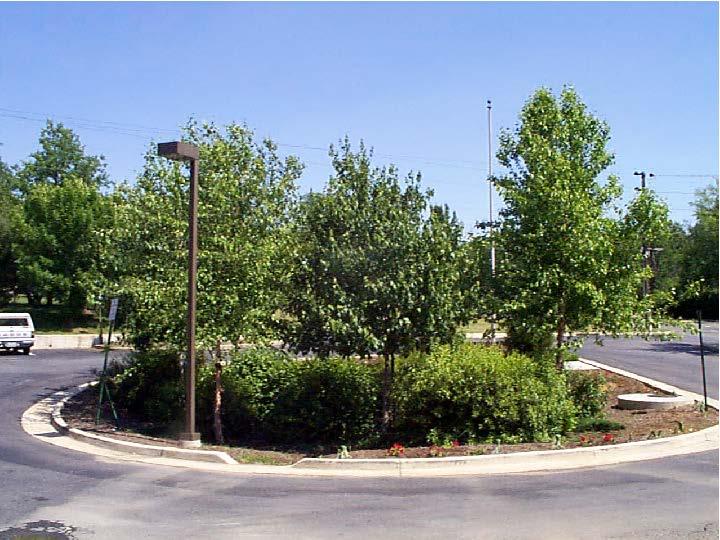
45 Green Roof Landscaping Criteria Plants need to resist and withstand Drought Fire Wind Heat-stress Etc.
46 Questions?

47 4.6 Rainwater Harvesting

48 Rainwater Harvesting Feasibility Criteria Minimal space or setback requirements Filters, pumps, and overflow devices are generally necessary Plumbing Code Roof material
49 Rainwater Harvesting Conveyance and Pretreatment Overflow conveyance must be provided. Pretreatment Options First Flush Diverters Leaf Screens Roof Washers Vortex Filters Level of pretreatment depends upon end use. Roof Washer

50 Rainwater Harvesting Design Criteria Sizing of tank should be based on consistent demand. Large tank + large demand = large credit.
51 Questions?
52 4.7 Impervious Surface Disconnection
53 Three Disconnection Options Simple Disconnection to Managed Turf Simple Disconnection to Forest Cover or Preserved Open Space Simple Disconnection to Compost Amended Filter Path
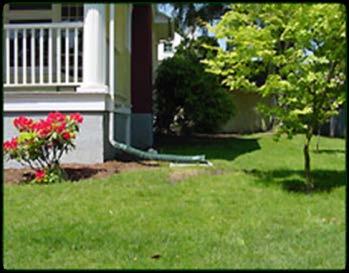
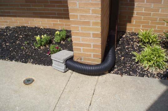
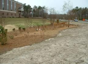
54 Disconnection to Managed Turf


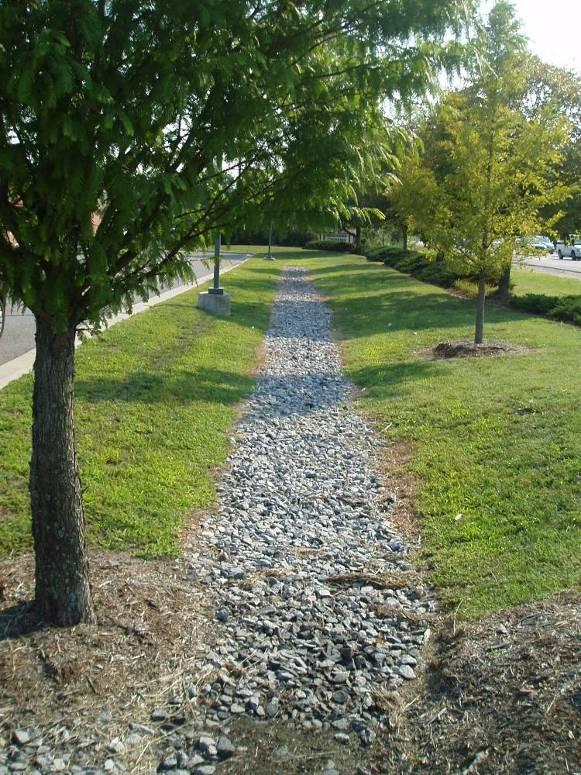
55 Disconnection to Forest Cover or Preserved Open Space

56 Disconnection to Compost Amended Filter Path
57 Disconnection to Managed Turf For rooftops, CDA 1,000 ft 2 per disconnection For non-rooftop, the longest contributing impervious area flow path 75 ft The available receiving area must be at least 10 ft 25 ft wide and 15 ft 100 ft long Width can be greater if runoff is conveyed via sheet flow or a level spreader
58 Disconnection to Forest Cover or Preserved Open Space Minimum disconnection length = 40 feet Sheet flow or level spreader required.
59 Disconnection to Compost Amended Filter Path Sheet flow or level spreader required. Freeboard required to keep runoff flowing through filter path. Work 2-4 inches of compost in to a depth of 6-10 inches.
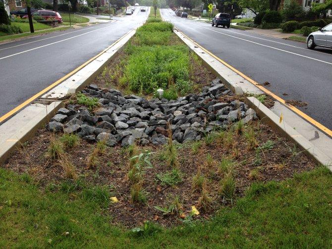
60 Level Spreaders 13 linear feet per each 1 cubic foot/second of inflow for turf cover. 40 linear feet per 1 cubic foot/second of inflow for forest cover.
61 Disconnection Volume Credits To Managed Turf: 50% credit on A/B soils; 25% credit on C/D soils To Forest Cover/Preserved Open Space: 75% credit To Compost Amended Filter Path: 50% credit
62 4.8 Open Channels

63 Grass Channel Flow depth for peak flow of water quality volume must be 4 or less. Residence time for water quality volume must be at least 9 minutes. A/B soils of compost amended: 20% credit C/D soils: 10% credit

64 Dry Swales and Wet Swales Dry Swale = Linear Bioretention Area Wet Swale = Linear Wetland / Wet Pond

65 Two-Stage Ditch Not included for water quality credit beyond grass channel, as they are more applicable to larger storm events. Can improve channel stability.

66 Regenerative Stormwater Conveyance Takes advantage of existing slopes. Greater flows and depth = more detailed specifications 100% volume credit

67 4.9 Stormwater Filtering Systems Image: Albemarle County

68 Stormwater Filtering Systems Must drain within 72 hours. Included in dry pond category??? Must treat 1 inch over entire drainage area.
69 4.10 Dry Detention Practices Must store and release 1 inch of runoff from entire drainage area over 24 hours.

70 Dry Detention Design Details Forebays and stabilized inlets recommended Pilot channels prohibited. Long flow paths preferred. Use of anti-clogging devices recommended.
71 4.11 Wet Detention Ponds Must store and release 1/2 inch of runoff from entire drainage area over 24 hours.

72 Wet Detention Design Details Adequate water balance required. 0.5 inches of permanent pool storage is recommended. Safety bench and aquatic bench recommended.
73 4.12 Stormwater Wetlands

74 4.12 Stormwater Wetlands Multiple depth zones recommended, varying between 6 and 48 deep. Flow path to width ratio should be at least 2:1.

75 Questions?
76 Appendix A Indicate Pre-Development Land Cover and Runoff Curve Numbers Area (acres) Cover Type Soil Type A CN Soil Type B CN Soil Type C CN Soil Type D CN Total % Cover Rv Forest Cover/Open Space % 0 Turf Cover % 0 Impervious Cover % 0 Total % 0.00 Indicate Post-Development Land Cover Area (acres) Cover Type Soil Type A CN Soil Type B CN Soil Type C CN Soil Type D CN Total % Cover Rv Forest Cover/Open Space % 0 Turf Cover % 0 Impervious Cover % 0 Total % 0.00 Is Site Located Within 1/2 Mile of Receiving Water Body? Is Site Located Within 1,000 sf of a Shellfish Bed? No No Water Quality Volume Receiving Water Body Storage Volume (cf) 0 Shellfish Bed Storage Volume (cf) 0 LID Practices (cf) 0 Ponds With Permanent Pool (cf) 0 Ponds Without Permanent Pool (cf) 0 Corresponding Rainfall (in)
77 2-year and 10-year Storm Events 1. Calculate Curve Number and Site Runoff Volume 2. Subtract Runoff Reduction Volume Achieved from Site Runoff Volume 3. Determine Reduced Curve Number based on Reduced Site Runoff Volume Flowrate (cfs) Time (min)
78 Appendix B Infiltration Testing Need a verified infiltration rate to utilize infiltration testing: Well Permeameter Method (USBR ) Double-Ring Infiltrometer (ASTM D 3385); Falling Head (single ring) test currently not recommended.

79 Appendix C Soil Amendments Specifications for Compost
80 Appendix D Peak Flow Calculations Recommended method for determining peak flow from a small storm event (0.5 inch, 1 inch, etc).