UFR+L FILTER REGULATOR + LUBRICATOR
|
|
|
- Jason Stewart
- 5 years ago
- Views:
Transcription

1 FEATURES The UFR+L filter regulator + lubricator is intended for the treatment of compressed air or compressed gas. Its function is that of supplying filtered, lubricated air at the desired pressure for feeding devices working with compressed air. Robust aluminium body. The maximum inlet pressure is 10 bar and 12 bar. Adjustment is made using the upper pressure regulating knob which can be locked in position. It is delivered with an attachment bracket and a pressure gauge indicating the downstream pressure. The bowl is made of plastic, with semiautomatic drain. AVAILABLE MODELS 1/4" to 1 diameters. G thread connections 5 µm standard filtration. ISO 9001 LIMITS OF USE Fluid Fluid pressure: WP Fluid temperature: WT Ambient temperature compressed air or nitrogen bar 0 C / +50 C -10 C / +60 C SPECIFICATIONS Technology Test pressure Regulator accuracy Filter capacity Lubricator capacity Drain Piston regulator 15 bar 0.2 bar 1/4" - 3/8" - 1/2" 3/4"- 1" 105 cc 210 cc 1/4" - 3/8" - 1/2" 3/4"- 1" 125 cc 235 cc Semi-automatic Pages 1/6

")

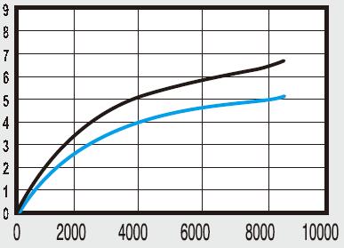
2 FLOW-RATE (litres/minute) 1/4 3/8 1/2 Black curve: flow-rate as a function of the inlet pressure Blue curve: flow-rate as a function of the outlet pressure Pressure (bar) Flow-rate: litres/ minute 3/4 1 Black curve: flow-rate as a function of the inlet pressure Blue curve: flow-rate as a function of the outlet pressure Pressure (bar) Flow-rate: litres/ minute Pages 2/6

3 CONSTRUCTION (1/4" - 3/8" - 1/2") No. Name Material No. Name Material 1 Pressure regulating knob Nylon 12 Semi-automatic drain POM 2 Cap Nylon + GF 13 Adjustment button POM 3 Adjustment screw Alloy steel 14 Filling screw Brass 4 Spring Alloy steel 15 Indicator light Polycarbonate 5 Piston Brass 16 Filling orifice Polycarbonate 6 Regulator filter body Aluminium alloy 17 Lubricator body Aluminium alloy 7 Plug stem Copper + NBR 18 Valve PU 8 Spring Alloy steel 19 Plug Copper 9 Filter support Nylon 20 Tube PU 10 Filtering element PE 21 Lubricator bowl PC 11 Filtering bowl PC 22 Bowl protection Nylon Pages 3/6

4 CONSTRUCTION (3/4" - 1") No. Name Material No. Name Material 1 Pressure regulating knob Nylon 11 Semi-automatic drain POM 2 Spring Alloy steel 12 Adjustment button POM 3 Cap Nylon + GF 13 Filling screw Brass 4 Regulator filter body Aluminium alloy 14 Indicator light Polycarbonate 5 Piston Aluminium 15 Filling pressure regulating knob Brass 6 Adapter Aluminium alloy 16 Lubricator body Aluminium alloy 7 Plug stem Copper + NBR 17 Check valve Copper 8 Filter element PE 18 Oil nozzle Copper 9 Bowl protection Nylon 19 Tube PU 10 Filtering bowl PC 20 Lubricator bowl PC Pages 4/6


5 DIMENSIONS (mm) (1/4" - 3/8" - 1/2") DIMENSIONS (mm) (3/4" - 1") Pages 5/6
6 WEIGHT (kg) 1/4 3/8 1/2 3/4 1" INSTALLATION 1 - The device has to be mounted horizontally. 2 - Mounting only on compressed air or nitrogen pipework. 3 - If need be, use the two rear attachment straps. 4 - Disconnect the pipework upstream. 5 - Comply with the way of mounting indicated on the body. 6 - Use a sealing material suitable for the fluid conditions.. 7- Pressurize the pipework slowly. USE 1 - To adjust the pressure, lift the pressure regulating knob 2 - Turn the pressure adjustment knob clockwise to increase the downstream pressure, and anti-clockwise to decrease it. 3 - Check the desired pressure on the pressure gauge. 4 - For the lubricator, fill the bowl through the upper orifice. 5 - Adjust the lubrication flow-rate with the needle screw. 6 - Check the oil level with the level indicator. 7 - Check the condensate level in the filter with the level indicator. If necessary, drain using the screw. NOTE: The device must depressurised before removing the filter and lubricator containers. SERVICING 1 - Periodically check the condensate level. 2 - Periodically check the oil level in the lubricator. 3 - If necessary, replace the filter cartridge. SPARE PARTS 1/4" - 3/8" - 1/2" 3/4" - 1" Filtration Code 40 µm µm Filtration Code 40 µm µm OPTION - Shut-off valve for the diameters: 1/4" - 3/8" - 1/2". Pages 6/6