CALDON Hydrocarbon Calibration Laboratory Our unique, comprehensive, in-house ultrasonic technology center
|
|
|
- Blake Norman Fleming
- 5 years ago
- Views:
Transcription

1 CALDON Hydrocarbon Calibration Laboratory Our unique, comprehensive, in-house ultrasonic technology center


2

3 The Hydrocarbon Calibration Laboratory The centerpiece of the Ultrasonic Technology Center is our CALDON* Hydrocarbon Calibration Laboratory. This laboratory is unequalled and sets Cameron apart from all other ultrasonic flowmeter suppliers in various ways. CALDON LEFM* 00 Series ultrasonic flowmeters are calibrated over a Reynolds number range that corresponds to the actual Reynolds number range the meter encounters in the field. This process ensures that once the meter is installed and operating, performance will be unaffected by changes in flow rate and liquid viscosity. The ability to calibrate in-house virtually eliminates the need for Cameron to use independent facilities, thereby dramatically reducing delivery cycles. One of the most important features of a flow laboratory is accuracy, or as referred to by metrological experts, the laboratory s measurement uncertainty. To calibrate a meter it is necessary to compare its registration to a known volume. For example, if,000 barrels of oil are passed through the meter, does it register,000 barrels? The uncertainty of the laboratory deals with the errors that might affect the known volume and how it compares to an international standard. When a meter has been calibrated in a laboratory with a low measurement uncertainty, its measurement in the field will be more accurate. The uncertainty within the Hydrocarbon Calibration Laboratory is ± 0.04% (0.03% using the small volume prover). The extreme stability of flow rate and temperature achievable at the laboratory provides our engineers with an unsurpassed tool for conducting fundamental research. This has contributed to a better understanding of the phenomena that affect ultrasonic flowmeters. 3
.")

.")
, and vents empty into a sump network (Photo 3).")
 is launched by the operator (Photo ).")
.")

![3 m3] between two consecutive detectors Used to calibrate all size meters between 4 and 0 in Uncertainty of ± 0.](/docs-images/89/99379742/images/4-7.jpg "04% 3 4 Small volume prover A calibration run is initiated when hydraulic pressure is removed allowing the poppet")
.")
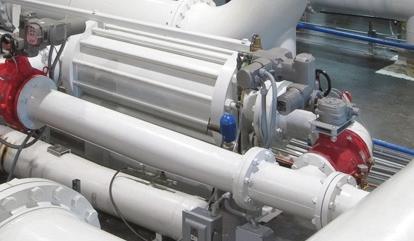
4 Laboratory Tour Filling/draining system Hydrocarbon liquid from any one of the three storage tanks fills the laboratory piping using the automated valve system (Photo ). One, two or all three available liquids may be used to calibrate a particular flow meter over a Reynolds number range that approximates that of the actual process. Once filled with liquid, a pressurizer can increase the laboratory piping pressure up to 35 psi. 3 Three,000-galUS storage tanks hold Exxsol D80 and two mineral oils (Drakeol 5 and Drakeol 3). Vents, shown in black (Photo ), are opened as the system is filling to eliminate air. Drains, shown in blue (Photo 3), and vents empty into a sump network (Photo 3). Liquid in the sump is pumped back into the appropriate storage tank. Ball prover A calibration run is initiated when the ball prover (Photo ) is launched by the operator (Photo ). The ball then drops down and is carried by the flow into the prover piping. A glass view of the prover piping illustrates the ball in motion (Photo 3). The position of the ball is monitored by a series of four detector switches (Photo 4). 0-in, 63-bbl [0-m3] ball prover with a capacity of 380 to 4,000 bbl/h [60 to,00 m3/h] Four detectors, bbl [3.3 m3] between two consecutive detectors Used to calibrate all size meters between 4 and 0 in Uncertainty of ± 0.04% 3 4 Small volume prover A calibration run is initiated when hydraulic pressure is removed allowing the poppet valve to close. The flowing test liquid causes the piston to move within the precision-machined flow tube of the prover (Photo ). Highly repeatable optical sensors are used to start and stop pulse and time measurements being made by the laboratory computer system. The piston, moving at the same rate of the test liquid, trips the switches allowing a determination of flow rate based on the measured volume and time (Photo ). 0.7 barrel with a capacity from 6 to 4,654 bbl/h Used for calibration of - to 6-in meters (directly or against a master meter) Uncertainty of ± 0.03% (± 0.04% with a master meter) 4

 shows the")


 Maximum flow")
![rate of 5,000 bbl/h [3,900 m3/h] 3 Calibrated by ball](/docs-images/89/99379742/images/5-6.jpg "prover The floor of the laboratory is recessed by 7")


 with sample")
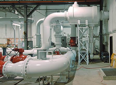
5 Master meters Flow passes through one or both master meter lines and into the calibration lines as shown by the yellow piping (Photo ). Pump room The illustration (Photo ) shows the location of the laboratory pumps. A third pump will be added in the future to expand the capacity of the laboratory. Two 0-in LEFM 80C master meters are used to calibrate meters 0 in and larger with flows greater than,500 bbl/h [,000 m3/h] Uncertainty of ± 0.08% 3 Two variable speed 50-hp pumps (Photo ) with adjustable frequency AC drives (Photo 3) Maximum flow rate of 5,000 bbl/h [3,900 m3/h] 3 Calibrated by ball prover The floor of the laboratory is recessed by 7 in to provide containment in case of a possible spill. Control room Data from all instruments, PLCs and meters are transmitted to two computers in the main control room Visitors can observe calibrations Two control room computers gather and process all calibration data and print the final report Main floor control panels Two panels with touch screen displays permit control of all laboratory operations from the main floor. One of two control panels (Photo ) with sample display screens (Photo and Photo 3) Emergency stop buttons are on the two panels, as well as at seven other strategic locations in the laboratory 3 5


. Heated coolant, shown in orange (Photo ), circulates back to the chiller.")

![Fluid temperature is controlled over a range of 59 to 95 degf [5 to 35 degc] by the 65 ton chiller system Tube](/docs-images/89/99379742/images/6-5.jpg "and shell heat exchanger contains approximately.")


 into any of the calibration lines.")
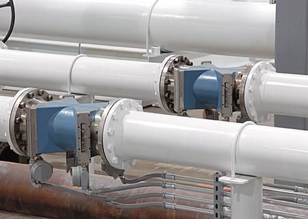
6 One large closed loop When using the prover, flow goes from the pump room, through one of the master meter lines, into the feed header, into one of the calibration lines, into the return header and then into the prover (Photo ). Flow continues through the prover and back into the pump room (Photo ). Temperature control The laboratory has a temperature control system that stabilizes liquid temperature at a desired value during a calibration run. This system removes heat added to the liquid by the pumps as it circulates through the laboratory piping loop. Coolant, shown in blue (Photo ), is pumped from the outside chiller (Photo ) into the shell of the lab s heat exchanger (Photo 3). Heated coolant, shown in orange (Photo ), circulates back to the chiller. The desired temperature set-point for the hydrocarbon liquid being used for the calibration is controlled by varying the rate at which coolant flows to the heat exchanger. Fluid temperature is controlled over a range of 59 to 95 degf [5 to 35 degc] by the 65 ton chiller system Tube and shell heat exchanger contains approximately.5 miles of internal tubing Temperature control system stabilizes calibration run conditions and permits hydro-carbon viscosity to be varied over a range of.5 to 00 centistokes Controlling hydrocarbon viscosity allows meters to be calibrated over the same Reynolds number range corresponding to installation conditions 3 Calibration lines Three calibration lines are shown in the illustration (Photo ). Flow of hydrocarbon liquid can be directed from the feed header (Photo ) into any of the calibration lines. The innermost line is used to calibrate - to 8-in meters (Photo 3). The middle calibration line is for 0- to 6-in meters. The third calibration line is designed for 0- to 4-in meters. Flow meters can be calibrated with customer provided meter runs or with laboratory piping. Meter electronics are connected to one of two panels (Photo 4), which transmits all data to the control room computers
7 Calibration Laboratory Overview Calibration Laboratory Specifications Laboratory Occupies approximately 7,360 ft. Piping pressurized up to 75 psi. Flow is circulated and controlled using two pumps. Pumps Two variable-speed 50-hp pumps located in a separate pump room. Maximum flow rate 5,000 bbl/h [3,900 m3/h] Minimum flow rate 63 bbl/h [0 m3/h] Meter sizes - to 4-in [50- to 600-mm] meters can be calibrated using three calibration lines. A 7.5 tonus crane is used for handling meters and piping. Prover 63-bbl [0-m3] unidirectional prover and a 0.75 bbl [0. m3] small volume prover. Master meters Two LEFM 80C 0-in meters installed in parallel. Calibration fluids Exxsol D80 and two mineral oils (Drakeol 5 and Drakeol 3) with nominal viscosities of cst, 5 cst and 50 cst. During a calibration, viscosity can be varied and controlled between approximately.5 and 00 cst. Storage tanks The oils are contained in three, double-walled storage tanks. The tanks are 0 ft high and ft in diameter with a,000 gallon capacity. Two inside tanks are located in a 5-ft deep containment pit. The third tank is located outside. Temperature control Temperature is controlled within a band of degf [5 35 degc] using a 65-tonUS chiller system. Oil passes through a tube and shell heat exchanger as it circulates in the lab. The oil temperature is controlled by adjusting the rate of coolant fed into the shell side of the heat exchanger from the chiller. Control The system is operated from a mezzanine level modular control room with full view of the entire laboratory. The system can also be operated from the laboratory floor via two touch-screen control panels. Safety Goggles and metal tipped shoes are required by personnel on the facility floor Uncertainty ± 0.04% ball prover 0.03% small volume prover ± 0.08% master meters 0.04% SVP and turbine meter ± 0.09% single-master meter Specifications may change without notice. 7
8 CALDON Hydrocarbon Calibration Laboratory cameron.slb.com/ultrasonicmeter *Mark of Schlumberger Other company, product, and service names are the properties of their respective owners. Copyright 06 Schlumberger. All rights reserved. MS-03 ML3 Rev