Bernard Benoit Project Management Inc. August DST File No.: GS-OT
|
|
|
- Norman Nichols
- 5 years ago
- Views:
Transcription


1 FINAL REPORT GEOTECHNICAL INVESTIGATION REPORT 2720 RICHMOND ROAD OTTAWA, ONTARIO Bernard Benoit Project Management Inc August 2012 DST File No.: GS-OT Thurston Dr., Suite 203 Phone: Ottawa, ON KG 5T9 Fax: CANADA
2 Final Geotechnical Investigation Report 2720 Richmond Road Expansion Ottawa, Ontario DST Reference No.: GS-OT Table of Contents 1. INTRODUCTION Purpose Scope of Services PROJECT DESCRIPTION FIELD INVESTIGATION PROCEDURES AND LABORATORY TESTING Field Investigation DESCRIPTION OF SUBSURFACE CONDITIONS Topsoil Asphalt Fill Sand to Silty Sand Till Bedrock Grain Size Analyses Groundwater DISCUSSION Shallow Footings Square Footings Strip Footings Floor Slab-On-Grade Lateral Earth Pressure Seismic Site Classification and Liquefaction Potential Frost Protection Site Grading and Drainage Backfill Materials Excavations and Dewatering Pavement Design Monitoring During Construction REFERENCES LIMITATIONS OF REPORT i DST CONSULTING ENGINEERS INC. August 2012
3 Final Geotechnical Investigation Report 2720 Richmond Road Expansion Ottawa, Ontario DST Reference No.: GS-OT List of Tables Table 4.1 Summary of sand fill grain size analyses... 5 Table 4.2 Summary of sand grain size analyses... 6 Table 4.3 Summary of grain size analysis results... 7 Table 4.4 Groundwater measurements... 7 Table 5.1 Geotechnical resistances and reactions for square footings on native undisturbed soil Table 5.2 Geotechnical resistances and reactions for strip footings on native undisturbed soil ii Appendices LIMITATIONS OF REPORT... A EXPLANATION OF TERMS USED IN REPORT... B FIGURES... C SOILS DATA... D SHEAR WAVE VELOCITY ASSESSMENT SITE CLASSIFICATION... E 2008 GEOTECHNICAL INVESTIGATION REPORT BY DST... F DST CONSULTING ENGINEERS INC. August 2012
4 Final Geotechnical Investigation Report 2720 Richmond Road Expansion Ottawa, Ontario DST Reference No.: GS-OT DST REFERENCE NO.: GS-OT INTRODUCTION 1.1 Purpose DST Consulting Engineers Inc. (DST) has been retained by Bernard Benoit Project Management Inc. to conduct a geotechnical investigation for the proposed building expansion located at 2720 Richmond Road in Ottawa, Ontario. This report addresses the field investigation undertaken, laboratory test program performed, factual report on subsurface conditions encountered, site classifications and asphalt design recommendations. Authorization to proceed with this work was received from Mr. Bernard Benoit of Bernard Benoit Project Management Inc., this report is prepared for the sole use of Bernard Benoit Project Management Inc and any use of the report, or any reliance on it by any other party, is the responsibility of such party. A previous geotechnical investigation and report titled, Preliminary Geotechnical Investigation, 2720 Richmond Road, Ottawa, Ontario was completed at this site location by DST in February 2008 under DST File No.: OE-OT and can be found in Appendix F. 1.2 Scope of Services The scope of work for the investigation is as follows One (1) borehole will be advanced up to auger refusal. Bedrock will be confirmed through coring up to 3 m into the bedrock. One (1) borehole will be advanced up to auger refusal, Advance three (3) geotechnical boreholes along the proposed fire route and parking lot up to a depth of 3 meter below existing grade to evaluate subsurface conditions and groundwater SPT sampling and in situ vane testing for cohesive soil; Collect undisturbed samples where cohesive soils are encountered. Installation of one groundwater standpipes to evaluate the static groundwater levels; Perform necessary laboratory tests for soil classification purposes including moisture content, grain size analysis, and if required hydrometer, and Atterberg limits on selected DST CONSULTING ENGINEERS INC. August 2012
5 Final Geotechnical Investigation Report 2720 Richmond Road Expansion Ottawa, Ontario DST Reference No.: GS-OT samples Prepare borehole logs indicating the types and location of existing soils Based on the soil and groundwater data obtained from this investigation and previous preliminary geotechnical soil investigation completed by DST Consulting Engineers, DST will provide a site classification and a geotechnical recommendation on the existing subsurface condition including footings design recommendations. DST CONSULTING ENGINEERS INC. August 2012
6 Final Geotechnical Investigation Report 2720 Richmond Road Expansion Ottawa, Ontario DST Reference No.: GS-OT PROJECT DESCRIPTION The site for the proposed development is located at 2720 Richmond Road Ottawa, Ontario. It is understood that the scope of work for the proposed expansion will consist of the following: The existing building located on the southeast side of Richmond Road of approximately 702 m 2 will be demolished and replaced with a building of approximately 890 m 2. The proposed building will be extended outside of the existing building foundation. A proposed fire route will be constructed with approximately width ranging between 6 and 7 m along the northeast Richmond Road to south east the proposed building. In addition, a proposed parking lot will be added as shown in Appendix C. Geotechnical information for the National Capital Region is available from the Natural Resources Canada website This indicates that the local terrain is dominated by alluvial sediments, predominantly sand and silt deposits. DST CONSULTING ENGINEERS INC. August 2012
7 Final Geotechnical Investigation Report 2720 Richmond Road Expansion Ottawa, Ontario DST Reference No.: GS-OT FIELD INVESTIGATION PROCEDURES AND LABORATORY TESTING 3.1 Field Investigation Site work was carried out onsite on the 24 th and the 25 th of July, In order to evaluate the subsurface soil conditions, the geotechnical boreholes were located at different parts of the site to provide a representative coverage for the proposed building, the fire route and the parking lot. The geotechnical investigation included the advancement of a total of five (5) boreholes and including the installation of one (1) slotted PVC standpipe for groundwater sampling and static groundwater level measurement. The approximate borehole locations are shown on the Borehole Location Plan (Figure 2) provided in Appendix C. To advance boreholes a truck mounted CME 75 drill rig equipped for geotechnical drilling and operated by George Downing Estates Drilling Limited was utilized. Boreholes were advanced with 108 mm inside diameter hollow stem augers. Representative soil samples were obtained from the auger flights and from the split spoon sampler used for the standard penetration test (SPT). The SPT involves driving a 51 mm diameter thick-walled sampler into the soil under the energy of a 63.5 kg weight falling through 760 mm. The number of blows required to drive the sampler 305 mm is known as the standard penetration blow count (N) which provides an indication of the condition or consistency of the soil. The standard penetration test was performed at intervals of 0.75 m from below the fill to 6.1 m and at intervals of 1.5 m at depths greater than 6.1 m in all boreholes. Results of the in-situ testing of soils are indicated on the borehole logs provided in Appendix D. Ground surface elevations for all advanced boreholes locations were surveyed by Annis, O Sullivan and Vollbekk Ltd. (AOV) and are referred to a geodetic benchmark in the area. DST CONSULTING ENGINEERS INC. August 2012
8 Final Geotechnical Investigation Report 2720 Richmond Road Expansion Ottawa, Ontario DST Reference No.: GS-OT DESCRIPTION OF SUBSURFACE CONDITIONS Details of the subsurface conditions for this project are given in the borehole logs and are discussed in detail below. All soil moistures and gradation analyses results are presented on the Borehole Logs and Grain size Analysis in Appendix D. 4.1 Topsoil Topsoil with variable gradations and organic content was encountered from surface at borehole location BH2 with a thickness of approximately 0.60 m. 4.2 Asphalt A total of four (4) boreholes were located on paved roadways. As such, a layer of asphaltic concrete was encountered at the surface of these borehole locations. The asphalt thickness encountered was 90, 100, 75 and 50 mm at borehole locations BH1, BH3, BH4 and BH5 respectively. 4.3 Fill Sand and gravel fill material was encountered directly beneath the asphalt at borehole locations BH1, BH3, BH4 and BH5 with thicknesses of 150, 150, 90 and 150 mm respectively. Sand fill with varying gradations of silt and gravel was encountered beneath the topsoil and sand and gravel fill at borehole locations BH1, BH2, BH3, BH4 and BH5 with thicknesses of 1.1, 1.1, 1.1, 1.2 and 0.5 m at depths of approximately 0.3 to 1.4 m, 0.6 to 1.7 m, 0.3 to 1.4 m, 0.2 to 1.4 m and 0.2 to 0.7 m respectively. SPT N values obtained within the sand fill range from 4 to 14 blows per 0.3 m penetration indicating very loose to compact condition. Moisture contents of tested samples varied from 4% to 8%. The results of the laboratory tests are summarized in Table 4.1. Table 4.1 Summary of sand fill grain size analyses Laboratory Results Grain Size Analyses Gravel % 2 to 7 Sand % 66 to 79 Fines % 14 to 32 Silty clay fill was encountered at borehole location BH1 with a thickness of 0.7 m at a depth of approximately 1.4 to 2.1 m. Silty clay fill was also encountered at borehole location BH2 with DST CONSULTING ENGINEERS INC. August 2012
9 Final Geotechnical Investigation Report 2720 Richmond Road Expansion Ottawa, Ontario DST Reference No.: GS-OT undetermined thickness below a depth of approximately 1.7 m. The thickness of this stratum is not defined in BH2 as borehole terminus was reached prior to the bottom of the stratum. In situ vane testing was attempted in BH2 but was not able to be advanced past the split spoon sampling depth due to dense material being encountered. SPT N values obtained within the clay range from 5 to 10 blows per 0.3 m penetration which correlate to an estimated undrained shear strength of between 25 and 100 kpa. The moisture content of the tested samples ranged from 18 to 25%. 4.4 Sand to Silty Sand Sand to silty sand was encountered borehole location BH4 with a thickness of 10.2 m at depths of approximately 0.8 to 11.0 m and at borehole locations BH1, BH3 and BH5 with undetermined thickness below depths of approximately 2.1 m, 0.8 m, and 0.7 m respectively. The thickness of this stratum is not defined at BH1, BH3 and BH5 as borehole terminus was reached prior to the bottom of the stratum. Within the sand, occasional silt lenses and cobbles were noted during the drilling process. SPT N values obtained within the sand range from 7 to 66 blows per 0.3 m penetration indicating loose to very dense condition. However, some SPT values may be artificially high due to the presence of cobbles within the stratum. Moisture contents of tested samples varied from 2 to 22%. The results of the laboratory tests are summarized in Table 4.2. Table 4.2 Summary of sand grain size analyses Laboratory Results Grain Size Analyses Gravel % 0 to 5 Sand % 67 to 90 Fines % 9 to Till Till composed of gravel, sand, silt and clay was encountered at borehole location BH4 with a thickness of 0.7 m at depths of approximately 11.0 to 11.7 m. A full SPT was not completed exclusively within the till material, however, the SPT N values obtained for the sample containing the till was 22 blows per 0.3 m penetration indicating a compact condition. Moisture content of the tested sample was 20%. DST CONSULTING ENGINEERS INC. August 2012
10 Final Geotechnical Investigation Report 2720 Richmond Road Expansion Ottawa, Ontario DST Reference No.: GS-OT Bedrock At borehole location BH4, auger refusal was encountered at a depth of 11.7 m. Shale (unweathered) bedrock was confirmed by coring 3.2 m into bedrock up to a depth of 14.9 m, using NQ size rotary drilling equipment. Total core recovery exceeded 98% with Rock Quality Designation (RQD) values of 94 to 98% which corresponds to a rating of excellent. 4.7 Grain Size Analyses Grain size analyses were performed on selected samples collected at borehole locations as shown in Table 4.3 below. Table 4.3 Summary of grain size analysis results Laboratory Results Grain Size Analyses Borehole Depth of sample (m) Gravel % Sand % Fines % BH BH BH BH BH BH BH BH Groundwater Upon completion of drilling, a piezometer was installed in BH5. The water depth above bedrock was observed to be 9.16 m below surface on July 26 th, This indicates that at the time of investigation the groundwater table was located at an approximate elevation of m. Groundwater levels are shown on the Borehole Logs and may fluctuate seasonally and in response to climatic conditions. Groundwater level measurements are summarized in Table 4.4 below. Table 4.4 Groundwater measurements July 26 th, 2012 Borehole Depth Measured (m) Elevation (m) BH DST CONSULTING ENGINEERS INC. August 2012
11 Final Geotechnical Investigation Report 2720 Richmond Road Expansion Ottawa, Ontario DST Reference No.: GS-OT DISCUSSION DST Consulting Engineers Inc. (DST) has been retained by Bernard Benoit Project Management Inc to conduct a geotechnical investigation for the proposed building expansion subject site located at 2720 Richmond Road in Ottawa, Ontario. The generalized stratigraphy of the existing site, based on the conditions encountered at borehole locations BH1 through BH5, consists of a variable thickness of fill that overlies sand with varying percentages of silt and gravel. This is underlain by predominantly sand and silt till over bedrock with a RQD rating of excellent. Unless noted otherwise, foundation design parameters are given for static, vertically and concentrically loaded foundations in compression. Dynamic, lateral, eccentric and uplift design parameters can be provided upon request, if applicable. All foundation design recommendations presented in this report are based on the assumption that an adequate level of construction monitoring during foundation excavation and installation will be provided. An adequate level of construction monitoring is considered to be: a) for shallow foundations, examination of all excavation surfaces prior to fill placement to ensure the integrity of the subgrade; and b) for earthwork, full-time monitoring and compaction testing. To accommodate the specified heated building of approximately 890 m 2 (9,580 ft 2 ) various options of shallow spread footings were considered. 5.1 Shallow Footings A foundation system utilizing conventional spread footings founded on undisturbed inorganic sand or silty sand is suitable for the anticipated structural loadings. Due to the depth of frost penetration it is suggested that the footings be installed at suitable depth with sufficient soil cover or if less soil cover is provided then the equivalent synthetic insulation should be provide for frost protection where footings are located at the perimeter of the building. To provide geotechnical reactions that meet the maximum Serviceability Limits States (SLS) loading (within maximum settlements of 25 mm) and Ultimate Limit States (ULS) resistances, reactions have been provided in the following tables. Due to the granular nature of the underlying material beneath the building footprint, most total and DST CONSULTING ENGINEERS INC. August 2012
12 Final Geotechnical Investigation Report 2720 Richmond Road Expansion Ottawa, Ontario DST Reference No.: GS-OT differential settlements are expected to occur during construction. Total settlement is not expected to exceed 25 mm with differential settlement less than 20 mm. In situations where column loads dictate footings wider than those widths provided are required, the geotechnical engineer should be contacted with specific column loads, and options can possibly be developed. All existing topsoil and/or other deleterious materials (including fill and construction debris) must be removed prior to the start of subgrade preparation. All excavations should be backfilled with approved engineered fill compacted to 100% of the SPMDD. Bearing areas will require very careful preparation. Following excavation all bearing surfaces should be cleaned of all organic, loose, disturbed, or slough material prior to concreting or placing compacted fill material. Bearing surfaces should be protected at all times from rain, freezing temperatures and the ingress of groundwater before, during and after construction. The engineered backfill should comprise Granular B Type I fill material meeting Ontario Provincial Standard Specifications SSP110S13. The fill should be placed and compacted in an unfrozen condition and the subgrade should be protected at all times from frost penetration. All foundation excavations and bearing surfaces should be inspected by a qualified geotechnical engineer to confirm the integrity of the bearing surface Square Footings Square Footing elements for the building should be founded on the native inorganic undisturbed sand and silt soil. Spread footings may be designed using limit state static bearing pressures listed in the Table 5.1. For these bearing pressure to be realized soil covers of 0.5 m, 1.0 m and 1.5 m are required respectively above the footing as described below. Minimum and maximum footing widths of 1.0 m and 2.5 m are recommended respectively. A minimum distance of one footing width is also required between adjacent footings. DST CONSULTING ENGINEERS INC. August 2012
13 Final Geotechnical Investigation Report 2720 Richmond Road Expansion Ottawa, Ontario DST Reference No.: GS-OT Table 5.1 Geotechnical resistances and reactions for square footings on native undisturbed soil Depth (m) Width of Footing (B) (m) Ultimate Bearing Capacity (kpa) Resistance at ULS (kpa) Reaction at SLS (kpa) Strip Footings Strip footing elements for the building should be founded on the native inorganic undisturbed sand and/or sandy silt soils. Spread footings may be designed using limit state static bearing pressures listed in the Table 5.2. Minimum and maximum footing widths of 0.5 m and 1.5 m are recommended. A minimum distance of one footing width is also required between adjacent footings. DST CONSULTING ENGINEERS INC. August 2012
14 Final Geotechnical Investigation Report 2720 Richmond Road Expansion Ottawa, Ontario DST Reference No.: GS-OT Table 5.2 Geotechnical resistances and reactions for strip footings on native undisturbed soil Depth (m) Width of Footing (B) (m) Ultimate Bearing Capacity (kpa) Resistance at ULS (kpa) Reaction at SLS (kpa) Floor Slab-On-Grade Concrete floor slab-on-grade construction is considered feasible provided certain precautions are undertaken. To accommodate the presence of variable fill materials beneath the slab-on-grade flooring, 0.3 m thick Granular B Type I fill compacted to at least 98% of standard proctor maximum dry density (SPMDD) is required. Very coarse material (larger than 25 mm diameter) should be avoided directly beneath the slab-on-grade to limit potential stress concentrations within the slab. To confirm existing fill material suitability, natural water content, SPMDD testing and grain size analysis should be conducted on granular materials used during construction. The slab should be structurally independent from walls and columns, which are supported by the foundations. This is to reduce any structural distress that may occur as a result of differential soil movement. If it is intended to place any internal non-load bearing partitions directly on the slab-ongrade, such walls should also be structurally independent from other elements of the building founded on the conventional foundation system so that some relative vertical movement of the walls can occur freely. The subgrade beneath the slab-on-grade should be protected at all times from rain, snow, freezing temperatures, excessive drying and the ingress of water. This applies during and after the construction period. DST CONSULTING ENGINEERS INC. August 2012
15 Final Geotechnical Investigation Report 2720 Richmond Road Expansion Ottawa, Ontario DST Reference No.: GS-OT Some relative movement between the slab-on-grade floor and adjacent walls or foundations and differential movement within the slab should be anticipated. Generally, if the recommendations outlined in this report are followed, these movements are estimated to be less than 10 mm. 5.3 Lateral Earth Pressure Structures may be designed to resist lateral earth pressures. When some degree of wall movement is allowed, then the design may be based on passive and active lateral earth pressures. The following expressions may be use in the above noted equations: K 0 = 1-Sin K a = K 0 / (1+K 0 ) K p = 1 / K a Where Angle of internal friction (30 degrees) K 0 = Co-efficient of earth pressure at rest condition K a = Co-efficient of earth pressure at active condition Kp= Co-efficient of earth pressure at passive condition 5.4 Seismic Site Classification and Liquefaction Potential The design peak horizontal acceleration was calculated as g based on 2005 National Building Code Seismic Hazard Map interpolation and it is shown in Appendix E. Assessment of liquefaction potential for loose granular soil were estimated using N 60 values interpreted from in situ SPT data applying Seed and Idriss (1971, 1982). The assessment considered Maximum Considered Earthquake (MCE) of magnitude of 7.5. Liquefaction analysis from the standard penetration resistance is evaluated and liquefaction is not imminent at the site. Factor of safety is in excess of 1.25 at foundation levels and below (>1.0 m depth). Based on the average standard penetration resistance (15 < N 60 < 50) of the overburden thickness of sand and silt (up to m in thickness) found in the area of the boreholes and the type of bedrock (shale) with an estimate shear wave velocity of 2000 m/s, the project site is classified as site Class D. F a and F v corresponding to Site Class D should be taken as 1.15 and 1.35 respectively (Table B and C, OBC 2006). DST CONSULTING ENGINEERS INC. August 2012
16 Final Geotechnical Investigation Report 2720 Richmond Road Expansion Ottawa, Ontario DST Reference No.: GS-OT Frost Protection Based on the Ministry of Environment published data, which is based on 85% probability, the design freezing index for Ottawa, Ontario has been estimated to be 1,050 degree-days Celsius (1,922 degree-days Fahrenheit). Based on this data, the calculated depth of frost penetration for sand to silty sand for an area which has been assumed to be kept clear of snow cover will be in the order of 1.8 m. To limit the effects of frost penetration, a minimum depth of soil cover of 1.5 m is required for perimeter footings of heated structures providing the structure is heated to at least 18 degrees Celsius and there is some heat loss through the foundation wall and floor. Isolated footings should have a minimum depth of soil cover of 1.8 m for frost protection. If less soil cover is provided then the equivalent synthetic insulation should be provide for frost protection. Perimeter footings should be placed below frost depth. If less soil cover is provided then the equivalent synthetic insulation should be provided for frost protection. Insulation with 25 mm of Styrofoam SM insulation or equivalent extending horizontally 1.22 m from the face of the wall footing. For the unheated isolated foundations the existing soil layer has frost susceptibility at the building location. Frost heave should be expected for these soils, due to soil moisture. To completely prevent frost heave of the underlying soils, the foundation should be placed with 1.8 m of soil cover or if less soil cover is provided foundations may be underlain with Styrofoam Highload insulation or equivalent of sufficient strength. Insulation with 63.5 mm of Styrofoam Highload insulation or equivalent must be placed beneath the footing and extending 2.44 m from the face of the wall footing should be provided. The Styrofoam should be installed in accordance with the manufacturer s directions. Note that Styrofoam insulation could be significantly degraded by a fuel spill. An alternate approach for any unheated concrete slab options is to sub-excavate all soil (1.8 m depth) and replace with compacted Granular B Type I fill compacted to 100% of standard proctor maximum dry density. Seasonal frost movements, if uninsulated, are expected to be less than 10 mm. DST CONSULTING ENGINEERS INC. August 2012
17 Final Geotechnical Investigation Report 2720 Richmond Road Expansion Ottawa, Ontario DST Reference No.: GS-OT Site Grading and Drainage Final site grading should be provided to direct water to areas remote from the proposed structure. Minimum landscape gradients of 2% are recommended to reduce the risk of runoff ponding in localized areas. Parking lots or landscaping within a zone of approximately two metres of the exterior perimeter of any structure should be graded to drain away from the structure at a minimum gradient of 3%. Downspouts should be positively directed away from the building to beyond the building backfill. Subsurface drainage below the floor slab is not required, provided the interior floor elevation is at least 200 mm higher than adjacent exterior grades and exterior surface drainage is maintained. If this is not the case, then subsurface drainage should be provided. 5.7 Backfill Materials Backfill against foundations should consist of an Ontario Provincial Standard Specifications (OPSS) Granular B Type I fill material. Existing native site soils which comprise of silty sand or clay will not be suitable for use as footing backfill as native soil material does not meet the OPSS requirements for Granular B Type I. Any soft or weak soils below foundation areas including any fill materials, which may be encountered during construction should be excavated under the direction of the geotechnical engineer to competent material and then backfilled either with OPSS Granular B Type I fill material meeting the requirements for OPSS 1010 as amended by Special Provision SSP110S13, compacted to 100% of standard proctor maximum dry density. Exterior backfill against foundation walls should be capped with an impervious layer. The fill should be placed and compacted in an unfrozen condition. 5.8 Excavations and Dewatering Based on the advanced geotechnical boreholes within the proposed subject development, the base of excavations will most likely occur within sand or silty sand deposits. At the time of the field investigation, the groundwater level was at an elevation of m, corresponding to 9.16 mbgs. Therefore dewatering may not be required if the proposed footing for the new development is above DST CONSULTING ENGINEERS INC. August 2012
18 Final Geotechnical Investigation Report 2720 Richmond Road Expansion Ottawa, Ontario DST Reference No.: GS-OT the existing found water table. Groundwater levels may fluctuate seasonally and in response to climatic conditions. Excavations deeper than 1.2 m should be braced in accordance with the Occupational Health and Safety Act (and Regulations for Construction Projects). The Occupational Health and Safety Act recognize four (4) broad classifications of soils, which are summarized below. TYPE 1 SOIL a) Is hard, very dense, only able to be penetrated with difficulty by a small sharp object; b) Has a low natural moisture content; c) Has a high degree of internal strength; d) Has no signs of water seepage; and e) Can only be excavated by mechanical equipment; TYPE 2 SOIL a) Is very stiff, dense and can be penetrated with moderate difficulty by a very sharp object; b) Has a low to medium natural moisture content; c) Has a medium degree of internal strength; d) Has a damp appearance after being excavated. TYPE 3 SOIL a) Is stiff to firm and compact to loose in consistency or is previously excavated soil; b) exhibits signs of surface cracking; c) exhibits signs of water seepage; d) if it is dry, may run easily into a well-defined conical pile; and e) has a low degree of internal strength. TYPE 4 SOIL a) is soft to very soft and very loose in consistency; b) very sensitive and upon disturbance is significantly reduced in natural strength; c) run easily or flow, unless it is completely supported before excavation procedure; d) has almost no internal strength; e) is wet or muddy; and f) exerts substantial fluid pressure on its supporting system. DST CONSULTING ENGINEERS INC. August 2012
19 Final Geotechnical Investigation Report 2720 Richmond Road Expansion Ottawa, Ontario DST Reference No.: GS-OT Generally the soils in the area of interest classify as Type 3, for soils that are compact to loose in consistency according to Regulations made under Health and Safety Act for construction projects, Part III-Excavations, Section 226. These should be assessed and confirmed in the field as construction progresses. No surface surcharges should be placed closer to the edge of the excavation than a distance equal to twice the depth of the excavation, unless the excavation support/retaining wall system has been designed to accommodate such surcharge. Attention should be paid to structures or buried service lines close to the excavation. As a general guideline, if a line projected down at 30 degrees from the horizontal from the base of foundations of adjacent structures intersects the extent of the proposed excavation, underpinning or special shoring techniques may be required to avoid damaging earth movements. The contractor should have suitable equipment to excavate the soils shown on the borehole logs and to meet the requirements of the project schedule and construction methodology. It is anticipated that the groundwater table is well below the anticipated invert of the building services and excavated trench wall consists of medium to high permeable soil (sand and silt), therefore groundwater control system will not be required for the trench excavation. However, it should be noted that groundwater levels will fluctuate seasonally and in response to climatic conditions. Excavation without shoring could be completed provided that the soils are sloped back sufficiently to maintain sidewall stability and protect workers. For excavations above the groundwater table, it is recommended that a side slopes no steeper than 1h to 1v for cohesive soils (e.g., clays) and 2h to 1v for cohesionless soils (e.g., sands) are maintained. Alternately, the excavation can be shored, for example, with sheet piling or a trench box, with the understanding that significant ground movements beyond the excavation are to be expected. 5.9 Pavement Design It is understood that a proposed fire route and an expansion for the existing parking lot will be taking place within the development subject site at the subject Site will include access roads and parking areas, which will be used by heavy and light vehicles. Table 6.1 and 6.2 below summarizes proposed asphalt designs for the parking lot and fire route respectively. DST CONSULTING ENGINEERS INC. August 2012
20 Final Geotechnical Investigation Report 2720 Richmond Road Expansion Ottawa, Ontario DST Reference No.: GS-OT Table 6.1 Parking lot pavement design recommendation Material Structure Layer Minimum Thickness (mm) Super pave 12.5 Level C Asphalt (PG58-34) 50 OPSS Granular A Base 150 OPSS Granular B (Type I) 300 Table 6.2 Fire route pavement design recommendation Material Structure Layer Minimum (mm) Super pave 12.5 Level C Asphalt (PG58-34) 40 Super pave 19 Level C Asphalt (PG58-34) Binder Course 60 OPSS Granular A Base 150 OPSS Granular B (Type I) 300 Paving is to be completed in accordance with the Ministry of Transportation of Ontario OPSS1151 and 310 and related Special Provisions or applicable City of Ottawa standards. Design grades should ensure that there are no low points where water can stand within the pavement structure. Grades should be uniform with positive slopes. The integrity of the subgrade and pavement structure layers must be protected and maintained during construction against water, frost and traffic. Prior to constructing the subbase, the subgrade should be cleaned and free of any topsoil and organic materials, debris and deleterious materials. The subgrade shall be compacted to 95% of SPMDD and sloped for drainage at a minimum of 3%. DST CONSULTING ENGINEERS INC. August 2012
21 Final Geotechnical Investigation Report 2720 Richmond Road Expansion Ottawa, Ontario DST Reference No.: GS-OT Excavation of the existing and reinstatement of the granular base material should be such that the surface of the new pavement matches the elevation of the existing pavement surface, as adjusted during the detailed design. Construction traffic is to be controlled to minimize damage and protect the integrity of the subgrade, base and subbase layers during construction. Butt joints, step joints, and tack coating are recommended to tie the new pavement with the existing pavement. At the transition where the new pavement structure meets the existing pavement structure, the subgrade is to be transitioned at a slope of 3 horizontal to 1 vertical (3H: 1V). All granular pavement materials should meet Ontario Provincial Standard Specification (OPSS) requirements and should be compacted to at least 98% of SPMDD. In particular it is imperative that the fines content does not exceed the 8% limit specified by OPSS for Granular A and B Type I. Asphaltic concrete should also be produced and placed in accordance with OPSS standards. Compaction efforts must be inspected and approved by a geotechnical engineer or his representative. All methods should be in accordance with applicable OPSS standards. Asphaltic concrete should also be produced and placed in accordance with OPSS standards. Compaction efforts must be inspected and approved by a qualified professional. All methods should be in accordance with applicable OPSS standards Monitoring During Construction All foundation design recommendations presented in this report are based on the assumption that an adequate level of construction monitoring by qualified geotechnical personnel during construction will be provided. An adequate level of construction monitoring is considered to be: a) for deep and shallow foundations: full-time monitoring and design review during construction; and b) for earthworks: full-time quality control and compaction testing. An important purpose of providing an adequate level of monitoring is to check that recommendations, based on data obtained at discrete borehole locations, are relevant to other areas of the site. In order to provide an adequate level of construction monitoring, qualified geotechnical personnel should manage and supervise the following tasks during construction: DST CONSULTING ENGINEERS INC. August 2012
22 Final Geotechnical Investigation Report 2720 Richmond Road Expansion Ottawa, Ontario DST Reference No.: GS-OT Shallow Foundations: Confirm that materials and methods meet specifications. Inspect foundation subgrades. Inspect excavation. Review shallow foundation installation/testing methods. Review compaction testing records. Provide review comments, including any discrepancies found with respect to specifications as well as this report, and the need for any modifications to the design or methods. Earthworks: Confirm that materials and methods meet specifications. Inspect subgrade prior to fill placement. Quality control of fill material. Review compaction testing records. Pavement: Confirm that materials and methods meet specifications and mix design. An adequate level of construction monitoring for granular pavement materials is considered to be inspection of the subgrade and compaction testing. An adequate level of construction monitoring for asphalt paving is considered full-time monitoring and testing of the compaction, asphalt cement content, gradation and Marshall properties of the mix. DST CONSULTING ENGINEERS INC. August 2012
23 Final Geotechnical Investigation Report 2720 Richmond Road Expansion Ottawa, Ontario DST Reference No.: GS-OT REFERENCES Bowles Joseph E., (1988). Foundation Analysis and Design, Fourth Edition, McGraw-Hill Book Company. Wolff, T.F. (1989), Spreadsheet Applications in Geotechnical Engineering, PWS Publishing Company, Boston, MA. Canadian Geotechnical Society (2006). Canadian Foundation Engineering Manual. Special Provisions SSP110S13, Amendment to Ontario Provincial Standard Specification OPSS 1010, April 2004, Material Specification for Aggregates Base, Subbase, Select Subgrade and Backfill Material. Seed, H.B.& Idriss, I.M. (1971), Simplified Procedure for Evaluating Soil Liquefaction Potential, Journal of the Soil Mechanics and Foundation Division, 107(SM9), p , ASCE. Seed, H.B. & Idriss, I.M. (1982), Ground Motions and Soil Liquefaction During Earthquakes, Earthquake Engineering Research Institute. Ontario Building Code (2006), Ontario Regulation 350/06 DST CONSULTING ENGINEERS INC. August 2012
24
25 Final Geotechnical Investigation Report 2720 Richmond Road Expansion Ottawa, Ontario DST Reference No.: GS-OT APPENDIX A LIMITATIONS OF REPORT DST CONSULTING ENGINEERS INC. August 2012
26 Final Geotechnical Investigation Report 2720 Richmond Road Expansion Ottawa, Ontario DST Reference No.: GS-OT LIMITATIONS OF REPORT GEOTECHNICAL STUDIES The data, conclusions and recommendations which are presented in this report, and the quality thereof, are based on a scope of work authorized by the Client. Note that no scope of work, no matter how exhaustive, can identify all conditions below ground. Subsurface and groundwater conditions between and beyond the testhole may differ from those encountered at the specific locations tested, and conditions may become apparent during construction which were not detected and could not be anticipated at the time of the site investigation. Conditions can also change with time. It is recommended practice that DST Consulting Engineers be retained during construction to confirm that the subsurface conditions throughout the site do not deviate materially from those encountered in the testholes. The benchmark and elevations used in this report are primarily to establish relative elevation differences between the testhole locations and should not be used for other purposes, such as grading, excavation, planning, development, etc. The design recommendations given in this report are applicable only to the project described in the text and then only if constructed substantially in accordance with details stated in this report. Since all details of the design may not be known, we recommend that we be retained during the final stage to verify that the design is consistent with our recommendations, and that assumptions made in our analysis are valid. Unless otherwise noted, the information contained herein in no way reflects on environmental aspects of either the site or the subsurface conditions. The comments given in this report on potential construction problems and possible methods are intended only for the guidance of the designer. The number of testholes may not be sufficient to determine all the factors that may affect construction methods and costs, e.g. the thickness of surficial topsoil or fill layers may vary markedly and unpredictably. The contractors bidding on this project or undertaking the construction should, therefore, make their own interpretation of the factual information presented and draw their own conclusion as to how the subsurface conditions may affect their work. Any results from an analytical laboratory or other subcontractor reported herein have been carried out by others, and DST Consulting Engineers Inc. cannot warranty their accuracy. Similarly, DST cannot warranty the accuracy of information supplied by the Client. DST CONSULTING ENGINEERS INC. August 2012
27 Final Geotechnical Investigation Report 2720 Richmond Road Expansion Ottawa, Ontario DST Reference No.: GS-OT APPENDIX B EXPLANATION OF TERMS USED IN REPORT DST CONSULTING ENGINEERS INC. August 2012

28 EXPLANATION OF TERMS USED IN REPORT SPT N VALUE: THE STANDARD PENETRATION TEST (SPT) N VALUE OF THE NUMBER OF BLOWS REQUIRED TO CAUSE A STANDARD 51 mm O.D. SPLIT BARREL SAMPLES TO PENETRATE 0.3 m INTO UNDISTURBED GROUND IN A BOREHOLE WHEN DRIVEN BY A HAMMER WITH A MASS OF 63.5 kg, FALLING FREELY A DISTANCE OF 0.76 m. FOR PENETRATION OF LESS THAN 0.3 m N VALUES ARE INDICATED AS THE NUMBER OF BLOWS FOR THE PENETRATION ACHIEVED. AVERAGE N VALUE IS DENOTED THUS Ñ. DYNAMIC CONE PENETRATION TEST (DCPT): CONTINUOUS PENETRATION OF A CONICAL STEEL POINT (51 mm O.D. 60 CONE ANGLE) DRIVEN BY 475 J IMPACT ENERGY ON A SIZE DRILL RODS. THE RESISTANCE TO CONE PENETRATION IS MEASURED AS THE NUMBER OF BLOWS FOR EACH 0.3 m ADVANCE OF THE CONICAL POINT INTO THE UNDISTURBED GROUND. SOILS ARE DESCRIBED BY THEIR COMPOSITION AND CONSISTENCY OR DENSENESS TEXTURAL CLASSIFICATION OF SOILS BOULDERS COBBLES GRAVEL SAND SILT CLAY GREATER THAN 200 mm 75 TO 200 mm 4.75 TO 75 mm TO 4.75 mm TO mm LESS THAN mm COARSE GRAIN SOIL DESCRIPTION (50% GREATER THAN mm) TERMINOLOGY TRACE OR OCCASIONAL SOME ADJECTIVE (e.g. SILTY OR SANDY) AND (e.g. SAND AND SILT) LESS THAN 10% 10 TO 20% 20 TO 35% 35 TO 50% CONSISTENCY*: COHESIVE SOILS ARE DESCRIBED ON THE BASIS OF THEIR UNDRAINED SHEAR STRENGTH (C U ) AND SPT N VALUES AS FOLLOWS C U (kpa) > 200 N (BLOWS / 0.3 m) < >30 VERY SOFT SOFT FIRM STIFF VERY STIFF HARD DENSENESS: COHESIONLESS SOILS ARE DESCRIBED ON THE BASIS ON DENSENESS AS INDICATED BY SPT N VALUES AS FOLLOWS N (BLOWS / 0.3 m) > 50 VERY LOOSE LOOSE COMPACT DENSE VERY DENSE ROCKS ARE DESCRIBED BY THEIR COMPOSITION AND STRUCTURAL FEATURES AND/OR STRENGTH RECOVERY: SUM OF ALL RECOVERED ROCK CORE PIECES FROM A CORING RUN EXPRESSED AS A PERCENT OF THE TOTAL LENGTH OF THE CORING RUN MODIFIED RECOVERY: SUM OF THOSE INTACT CORE PIECES, 100 mm+ IN LENGTH EXPRESSED AS A PERCENTAGE OF THE LENGTH OF THE CORING RUN. THE ROCK QUALITY DESIGNATION (R.Q.D) FOR MODIFIED RECOVERY IS: R.Q.D (%) VERY POOR POOR FAIR GOOD EXCELLENT LEGEND OF RECORDS FOR BOREHOLES: SYMBOLS AND ABBREVATIONS FOR SAMPLE TYPE SS SPLIT SPOON SAMPLE WS WASH SAMPLE TW THIN WALL SHELBY TUBE SAMPLE AS AUGER (GRAB) SAMPLE PH SAMPLER ADVANCED BY HYDRAULIC PRESSURE TP THIN WALL PISTON SAMPLE WH SAMPLER ADVANCED BY SELF STATIC WEIGHT PM SAMPLER ADVANCED BY MANUAL PRESSURE SC SOIL CORE RC ROCK CORE WATER LEVEL *HIERARCHY OF SOIL STRENGTH PREDICTION: 1) LABORATORY TRIAXIAL TESTING. 2) FIELD INSITU VANE TESTING. 3) LABORATORY VANE TESTING. 4) SPT VALUES. 5) POCKET PENETROMETER.
29 Final Geotechnical Investigation Report 2720 Richmond Road Expansion Ottawa, Ontario DST Reference No.: GS-OT APPENDIX C FIGURES DST CONSULTING ENGINEERS INC. August 2012


30
31
32 Final Geotechnical Investigation Report 2720 Richmond Road Expansion Ottawa, Ontario DST Reference No.: GS-OT APPENDIX D SOILS DATA DST CONSULTING ENGINEERS INC. August 2012
33 LOG OF BOREHOLE BH1 DST REF. No.: GS-OT CLIENT: Bernard Benoit Project Management Inc PROJECT: Geotechnical Investigation - Proposed Building Expansion LOCATION: 2720 Richmond Road, Ottawa, Ontario SURFACE ELEV.: metres Drilling Data METHOD: Hollow Stem Auger DIAMETER: 108 mm ID DATE: 24 July 2012 COORDINATES: m N, m E DEPTH (m) ELEV. (m) Water Data Wp % MOISTURE 20 W WI Symbol MATERIAL DESCRIPTION Blows/0.3m GR SA SI CL ASPHALT - 90 mm FILL - SAND & CRUSHED GRAVEL - trace silt, brown mm FILL - SAND - some silt, trace gravel, brown, loose FILL - CLAY - silty, some sand, brown/grey, firm SAND - some silt, trace gravel, brown/grey, occasional cobbles, compact End of Borehole at 2.6 m SAMPLE # AS1 SS1 SS2 SS3 SAMPLE TYPE 'N' VALUE VANE (kpa) SPT (N) DCPT REMARKS & GRAINSIZE DISTRIBUTION (%) 1 81 (18) BOREHOLE (STANDARD) - OTTAWA GS OT RICHMOND.GPJ DST_MIN.GDT 9/8/ DST Consulting Engineers Inc THURSTON DRIVE OTTAWA, ONTARIO, K1G 5T9 PH: (613) FX: (613) ottawa@dstgroup.com Web: SAMPLE TYPE LEGEND Auger Sample Rock Core Split Spoon Sample Hiller Peat Sampler Bulk Sample 70mm Thin Wall Tube Bentonite Sand ENCLOSURE 1 PAGE 1 OF 1
34 LOG OF BOREHOLE BH2 DST REF. No.: GS-OT CLIENT: Bernard Benoit Project Management Inc PROJECT: Geotechnical Investigation - Proposed Building Expansion LOCATION: 2720 Richmond Road, Ottawa, Ontario SURFACE ELEV.: metres Drilling Data METHOD: Hollow Stem Auger DIAMETER: 108 mm ID DATE: 24 July 2012 COORDINATES: m N, m E DEPTH (m) ELEV. (m) Water Data Wp % MOISTURE 20 W WI Symbol MATERIAL DESCRIPTION Blows/0.3m GR SA SI CL TOPSOIL - SAND - some silt, trace organics, brown FILL - SAND - silty, trace gravel, brown, compact FILL - CLAY - silty, some sand, brown/red, stiff End of Borehole at 2.5 m SAMPLE # AS1 SS1 SS2 SS3 SAMPLE TYPE 'N' VALUE VANE (kpa) SPT (N) DCPT REMARKS & GRAINSIZE DISTRIBUTION (%) 66 (32) 100+ SPT Result 50 blows / 150 mm BOREHOLE (STANDARD) - OTTAWA GS OT RICHMOND.GPJ DST_MIN.GDT 9/8/ DST Consulting Engineers Inc THURSTON DRIVE OTTAWA, ONTARIO, K1G 5T9 PH: (613) FX: (613) ottawa@dstgroup.com Web: SAMPLE TYPE LEGEND Auger Sample Rock Core Split Spoon Sample Hiller Peat Sampler Bulk Sample 70mm Thin Wall Tube Bentonite Sand ENCLOSURE 2 PAGE 1 OF 1
35 LOG OF BOREHOLE BH3 DST REF. No.: GS-OT CLIENT: Bernard Benoit Project Management Inc PROJECT: Geotechnical Investigation - Proposed Building Expansion LOCATION: 2720 Richmond Road, Ottawa, Ontario SURFACE ELEV.: metres Drilling Data METHOD: Hollow Stem Auger DIAMETER: 108 mm ID DATE: 24 July 2012 COORDINATES: m N, m E DEPTH (m) ELEV. (m) Water Data Wp % MOISTURE 20 W WI Symbol MATERIAL DESCRIPTION Blows/0.3m GR SA SI CL ASPHALT mm FILL - SAND & CRUSHED GRAVEL - trace silt, brown mm FILL - SAND - some silt, trace gravel, brown, very loose SAND - trace silt to silty, trace gravel, brown/grey, loose SAMPLE # AS1 SS1 SS2 SAMPLE TYPE 'N' VALUE 4 7 VANE (kpa) SPT (N) DCPT REMARKS & GRAINSIZE DISTRIBUTION (%) 7 79 (14) End of Borehole at 3.0 m SS BOREHOLE (STANDARD) - OTTAWA GS OT RICHMOND.GPJ DST_MIN.GDT 9/8/ DST Consulting Engineers Inc THURSTON DRIVE OTTAWA, ONTARIO, K1G 5T9 PH: (613) FX: (613) ottawa@dstgroup.com Web: SAMPLE TYPE LEGEND Auger Sample Rock Core Split Spoon Sample Hiller Peat Sampler Bulk Sample 70mm Thin Wall Tube Bentonite Sand ENCLOSURE 3 PAGE 1 OF 1
36 LOG OF BOREHOLE BH4 DST REF. No.: GS-OT CLIENT: Bernard Benoit Project Management Inc PROJECT: Geotechnical Investigation - Proposed Building Expansion LOCATION: 2720 Richmond Road, Ottawa, Ontario SURFACE ELEV.: metres Drilling Data METHOD: Hollow Stem Auger DIAMETER: 108 mm ID DATE: 24 July 2012 COORDINATES: m N, m E DEPTH (m) ELEV. (m) Water Data Wp % MOISTURE 20 W WI Symbol Blows/0.3m GR SA SI CL ASPHALT - 75 mm FILL - SAND & CRUSHED GRAVEL - trace silt, brown - 90 mm FILL - SAND - some silt, trace gravel, organics, brown, loose SAND - trace silt to silty, trace gravel, brown/grey, occasional cobbles and silt lenses, compact to very dense cobbles MATERIAL DESCRIPTION SAMPLE # AS1 SS1 SS2 SS3 SS4 SS5 SAMPLE TYPE 'N' VALUE VANE (kpa) SPT (N) DCPT REMARKS & GRAINSIZE DISTRIBUTION (%) 0 90 (9) SS silt SS7 SS (31) SS SS (14) BOREHOLE (STANDARD) - OTTAWA GS OT RICHMOND.GPJ DST_MIN.GDT 9/8/ TILL - SAND & SILT - some gravel, clay, grey, compact BEDROCK DST Consulting Engineers Inc THURSTON DRIVE OTTAWA, ONTARIO, K1G 5T9 PH: (613) FX: (613) ottawa@dstgroup.com Web: RC1-1.6 m, RQD - 96%, REC - 100% RC2-1.6 m, RQD - 99%, REC - 98% End of Borehole at 14.9 m Auger Sample Split Spoon Sample Bulk Sample SS11 RC1 RC2 22 SAMPLE TYPE LEGEND Rock Core Hiller Peat Sampler 70mm Thin Wall Tube Bentonite Sand ENCLOSURE 4 PAGE 1 OF 1

37 LOG OF BOREHOLE BH5 DST REF. No.: GS-OT CLIENT: Bernard Benoit Project Management Inc PROJECT: Geotechnical Investigation - Proposed Building Expansion LOCATION: 2720 Richmond Road, Ottawa, Ontario SURFACE ELEV.: metres Drilling Data METHOD: Hollow Stem Auger DIAMETER: 108 mm ID DATE: 25 July 2012 COORDINATES: m N, m E DEPTH (m) ELEV. (m) Water Data Wp % MOISTURE 20 W WI Symbol Blows/0.3m GR SA SI CL ASPHALT - 50 mm FILL - SAND & CRUSHED GRAVEL - trace silt, brown mm FILL - SAND - some silt, trace gravel, brown, loose SAND - trace silt to silty, trace gravel, brown/grey, occasional cobbles and silt lenses, compact to very dense cobbles MATERIAL DESCRIPTION SAMPLE # SS1 SS2 SS3 SS4 SS5 SAMPLE TYPE 'N' VALUE VANE (kpa) SPT (N) DCPT REMARKS & GRAINSIZE DISTRIBUTION (%) Water level at 9.16 mbgs on July 26, (27) SS (29) silt SS7 SS SS SS End of Borehole at 9.8 m BOREHOLE (STANDARD) - OTTAWA GS OT RICHMOND.GPJ DST_MIN.GDT 9/8/ DST Consulting Engineers Inc THURSTON DRIVE OTTAWA, ONTARIO, K1G 5T9 PH: (613) FX: (613) ottawa@dstgroup.com Web: Auger Sample Split Spoon Sample Bulk Sample SAMPLE TYPE LEGEND Rock Core Hiller Peat Sampler 70mm Thin Wall Tube Bentonite Sand ENCLOSURE 5 PAGE 1 OF 1
38 GRAINSIZE ANALYSIS 100 SIEVE SIZE 3" 1" 3/8" #4 #8 #16 #30 #50 #100 #200 #270 U.S. Standard Sieve Sizes PERCENT PASSING PARTICLE SIZE IN MILLIMETRES Unified Soil Classification System COB'L GRAVEL SAND Coarse Fine Coarse Medium Fine SILT & CLAY GS GS OT RICHMOND.GPJ DST_MIN.GDT 30/7/12 LEGEND: BOREHOLE BH1 DEPTH 2.0 BOREHOLE BH2 DEPTH 1.5 BOREHOLE BH3 DEPTH 0.8 BOREHOLE BH4 DEPTH 1.5 BOREHOLE BH4 DEPTH 6.0 BOREHOLE BH4 DEPTH 9.1 BOREHOLE BH5 DEPTH 0.8 BOREHOLE BH5 DEPTH 5.3 August 2012 Reference No.: GS-OT Geotechnical Investigation - Proposed Building Expansion DST CONSULTING ENGINEERS INC. ENCLOSURE 6
39 Final Geotechnical Investigation Report 2720 Richmond Road Expansion Ottawa, Ontario DST Reference No.: GS-OT APPENDIX E SHEAR WAVE VELOCITY ASSESSMENT SITE CLASSIFICATION DST CONSULTING ENGINEERS INC. August 2012
40 2005 National Building Code Seismic Hazard Calculation INFORMATION: Eastern Canada English (613) français (613) Facsimile (613) Western Canada English (250) Facsimile (250) Requested by:, DST Consulting Engineers Inc Site Coordinates: North West User File Reference: 2720 Richmond Road July 30, 2012 National Building Code ground motions: 2% probability of exceedance in 50 years ( per annum) Sa(0.2) Sa(0.5) Sa(1.0) Sa(2.0) PGA (g) Notes. Spectral and peak hazard values are determined for firm ground (NBCC 2005 soil class C - average shear wave velocity m/s). Median (50th percentile) values are given in units of g. 5% damped spectral acceleration (Sa(T), where T is the period in seconds) and peak ground acceleration (PGA) values are tabulated. Only 2 significant figures are to be used. These values have been interpolated from a 10 km spaced grid of points. Depending on the gradient of the nearby points, values at this location calculated directly from the hazard program may vary. More than 95 percent of interpolated values are within 2 percent of the calculated values. Ground motions for other probabilities: Probability of exceedance per annum Probability of exceedance in 50 years Sa(0.2) Sa(0.5) Sa(1.0) Sa(2.0) PGA % % % References National Building Code of Canada 2005 NRCC no ; sections 4.1.8, , , , and Appendix C: Climatic Information for Building Design in Canada - table in Appendix C starting on page C-11 of Division B, volume 2 User s Guide - NBC 2005, Structural Commentaries NRCC no F (in preparation) Commentary J: Design for Seismic Effects Geological Survey of Canada Open File xxxx Fourth generation seismic hazard maps of Canada: Maps and grid values to be used with the 2005 National Building Code of Canada (in preparation) See the websites and for more information 45.5 N 45 N km Aussi disponible en français 76 W 75.5 W
41 Final Geotechnical Investigation Report 2720 Richmond Road Expansion Ottawa, Ontario DST Reference No.: GS-OT APPENDIX F 2008 GEOTECHNICAL INVESTIGATION REPORT BY DST DST CONSULTING ENGINEERS INC. August 2012

42 PRELIMINARY GEOTECHNICAL INVESTIGATION 2720 Richmond Road Ottawa, Ontario Prepared for City of Ottawa Corporate Service Department Real Property Asset Management 110 Laurier Avenue West, 5 th Floor Ottawa, ON K1P 1J1 February 2008 FINAL REPORT 5 Copies City of Ottawa 1 Copy DST Consulting Engineers Inc. DST File No.: OE-OT DST Consulting Engineers Inc Thurston Drive, Suite 203, Ottawa, Ontario, K1G 5T9 Tel.: (613) Fax: (613) ottawa@dstgroup.com
43 Preliminary Geotechnical Investigation 2720 Richmond Road, Ottawa, Ontario City of Ottawa DST File No.: OEOT Table of Contents Section 1. Introduction General Section 2. Site Description Section 3. Field Investigation Section 4. Laboratory Testing Water Content Grain Size Analysis Section 5. Subsurface Conditions Surface Conditions Subsurface Profile Asphalt Pavement Fill material Silty Sand to Silt and Sand Auger Refusal and Bedrock Groundwater Conditions Section 6. Discussions and Recommendations General Conceptual Project Details Site Preparation and Grading Foundation Spread Footings Pile Foundation Floor Slab-On-Grade Pavement Structure Frost Depth Excavations Seismic Liquefaction Hazard Assessment Section 7. Summary and Conclusions Section 8. Closure General DST CONSULTING ENGINEERS INC. 10/23/08 1
44 Preliminary Geotechnical Investigation 2720 Richmond Road, Ottawa, Ontario City of Ottawa DST File No.: OEOT Appendices Appendix A Appendix B Appendix C Appendix D Appendix E Limitations of Report Figures Borehole Logs Grain Size Analysis and Slug Test Results Copy of MOE Well Record (to be included in the final report) DST CONSULTING ENGINEERS INC. 10/23/08 2
45 Preliminary Geotechnical Investigation 2720 Richmond Road, Ottawa, Ontario City of Ottawa DST File No.: OEOT Introduction 1.1 General DST Consulting Engineers Inc. has carried out a preliminary geotechnical investigation at 2720 Richmond Road, in Ottawa, Ontario (the Site ). The investigation was completed in accordance with the workplan described in the DST proposal dated February 4, Authorization to proceed with this work was received from Mr. Greg Montcalm of the City. This report is prepared for the sole use of the City and any use of the report, or any reliance on it by any other party, is the responsibility of such party. It is understood that the possible future use of the Site is low to medium density (20 to 40 units per hectare or 8 to 16 units per acre) residential land use. The purpose of the preliminary geotechnical investigation was to explore the subsurface conditions as per the Terms of Reference at the southern part of the Site (Ref.: Figure 2 provided in Appendix B showing extent of the Geotechnical Investigation), and provide geotechnical recommendations pertaining to the Site preparation and foundation design for the proposed development. Once the building design details are known for the development, a more thorough geotechnical investigation should be completed based on final building designs. DST CONSULTING ENGINEERS INC. 10/23/08 1-1
46 Preliminary Geotechnical Investigation 2720 Richmond Road, Ottawa, Ontario City of Ottawa DST File No.: OEOT Site Description The Site is located on the east (south-east) side of Richmond Road between Carling Avenue and Pinecrest Road in Ottawa, Ontario. The Site location is illustrated on Figure 1, Appendix B. The Site is approximately trapezoidal-shaped, 2.31 ha in area, with a frontage of m along Richmond Road and a maximum depth of approximately 203 m along its eastern boundary. Vehicular access to the Site is by a U-shaped asphalt driveway from Richmond Road. Major Site features include a three-storey main building and a one-storey slab-on-grade building (annex building). The immediate areas surrounding the buildings are covered by asphalt pavement followed by green spaces. The City has indicated that the front yard and the exterior of the three storey building are designated heritage. A site plan is illustrated as Figure 2, Appendix B. DST CONSULTING ENGINEERS INC. 10/23/08 2-1
47 Preliminary Geotechnical Investigation 2720 Richmond Road, Ottawa, Ontario City of Ottawa DST File No.: OEOT Field Investigation The number of boreholes/monitoring wells and their general locations were determined in consultation with the City s Project Manager as well as to satisfy the requirements of the proposed workplan. The geotechnical boreholes were located at various parts of the Site to provide a representative coverage of the Site in order to evaluate subsurface soil conditions. The preliminary geotechnical investigation included the advancement of four (4) boreholes equipped with monitoring wells for groundwater sampling and static groundwater level measurement within the Site. The approximate borehole/monitoring well locations are illustrated on the Borehole Location Plan, Figure 2, provided in Appendix B. The drilling was carried out on February 4 and 5, 2008, under the supervision of a field supervisor from DST. All boreholes were advanced using a CME 75 truck-mounted drill rig equipped with hollow stem augers. Within each Borehole, a standard split spoon sampler was used for soil sampling and performing standard penetration tests (SPT) at regular 0.75 m intervals. The SPT provides indications of relative density of subsurface soil. Boreholes at locations BHMW1, BHMW2 and BHMW4 were advanced to depths of approximately 10 metres below surface grade (mbsg). Augur refusal was not encountered at borehole locations BHMW1, BHMW2 and BHMW4 during this investigation. Borehole location BHMW3 was advanced to a depth of mbsg, where it encountered Auger refusal. The soil samples were visually examined for textural classification and identification, and preserved in plastic bags. All soil samples were transported to the DST s laboratory in Ottawa for laboratory testing on selected samples At borehole location BHMW3, bedrock was confirmed by coring 4 m into the bedrock to a final depth of mbsg using rotary core drilling equipped with BX size diamond bit. The cores were visually described, measured and placed in core boxes for further identification and observation by DST s geotechnical engineer. A monitoring well was installed into each borehole on its completion in accordance with the Ontario Water Resources Act R.R.O. 1990, Regulation 903, as amended. The monitoring wells were constructed using 50 mm diameter, schedule 40, flush-joint threaded polyvinyl chloride (PVC) screen and solid riser. Details of the installed monitoring wells at each borehole location are provided on the DST CONSULTING ENGINEERS INC. 10/23/08 3-1
48 Preliminary Geotechnical Investigation 2720 Richmond Road, Ottawa, Ontario City of Ottawa DST File No.: OEOT borehole logs in Appendix C. Clean sand (sand pack) was added around annular space of well screen to at least 30 cm above the top of the screen, followed by bentonite seal to approximately 15 cm below the existing ground surface. The tops of the riser pipes were sealed with a j-plug and concealed with a flush-mount casing. A copy of the MOE Well Record is also included in Appendix E. A slug test was conducted at monitoring well location BHMW3 to determine in-situ hydraulic conductivity of the soil. The test was initiated by causing an instantaneous change in the water level within the monitoring well. The recovery of water level with time was then observed. Following this sudden change, the well s water level returns to static conditions as water moves into it in response to the hydraulic gradient. The Hvorslev method of analysis, which assumes a homogenous, isotropic and infinite medium, was used. The result for the borehole/monitoring well BHMW3 which was tested indicates a hydraulic conductivity of approximately cm/sec for the silty sandy layer. Given that the testing was done only at a single location, it is possible that hydraulic conductivities at other borehole locations may be different from that indicated by testing at monitoring well location BHMW3. The ground surface elevations at each borehole location were provided by City of Ottawa, and are understood to be referenced to geodetic datum. Approximate ground surface elevations are shown on borehole logs presented in Appendix C. DST CONSULTING ENGINEERS INC. 10/23/08 3-2
49 Preliminary Geotechnical Investigation 2720 Richmond Road, Ottawa, Ontario City of Ottawa DST File No.: OEOT Laboratory Testing The soil samples were visually re-examined in the laboratory by a geotechnical engineer for textural classification. Laboratory tests were carried out on a number of selected soil samples to acquire information with regards to the physical and geotechnical properties of the subsurface soil condition. Soil sampling and classification were completed in accordance with the Canadian Foundation Engineering Manual (CFEM, 2006). Classification and laboratory tests, including grain size analysis and moisture content were performed in the laboratory on selected soil samples to aid in the selection of engineering properties. 4.1 Water Content Water content testing was carried out for all soil samples. The results of natural water contents are presented on the borehole logs (Appendix C). 4.2 Grain Size Analysis Sieve size analysis was performed on representative granular soil samples obtained from various depths and borehole locations shown in Table 4.1. A summary of the grain size analyses results are provided in Table 4.1 and grain size analysis graphs included in Appendix D. Table 4.1: Summary of Grain size distribution of selected soil samples Borehole No./ Sample ID % Content Soil Classification Sample Conforming to OPSS for: Gravel Sand Silt & Clay BHMW1/SS SAND silty, trace gravel N/A BHMW2/SS SAND & SILT trace gravel Select Subgrade Material BHMW3/SS SAND silty, trace gravel N/A BHMW4/SS SAND some silt, trace gravel N/A: Soil sample does not conform to OPSS requirements for Granular A or B or SSM Select Subgrade Material DST CONSULTING ENGINEERS INC. 10/23/08 4-1
50 Preliminary Geotechnical Investigation 2720 Richmond Road, Ottawa, Ontario City of Ottawa DST File No.: OEOT Subsurface Conditions 5.1 Surface Conditions As discussed previously, the ground surface at the Site is mainly covered by asphalt pavement surrounding the buildings, followed by green spaces. The overall Site topography is relatively flat. 5.2 Subsurface Profile The subsurface conditions encountered in the boreholes are shown on the borehole logs provided in Appendix C. The results of the laboratory moisture content and standard penetration test resistances (N-values) are also shown on the borehole logs. The results of grain size analyses are presented in Appendix D. The borehole logs indicate the subsurface conditions and water levels at the borehole locations only. Subsurface conditions and water levels at other locations may differ from conditions observed at the boreholes locations. A review of the borehole logs BHMW1 to BHMW4, inclusive, drilled in the paved area indicate that the sub-surface conditions of the Site consist of surficial layer of Asphalt pavement, which was underlain by a variable fill material consisting of sand and gravel or gravelly sand or sand and silt. A layer of clay material, approximately 0.5 m thick, embedded in the fill material was also encountered at borehole location BHMW2. The fill material was underlain by a layer of silty sand/sand with some silt, which extended to end of the boreholes. The soil overburden is underlain by shale bedrock, which was confirmed at borehole location BHMW3 at 11.2 metres below surface grade (mbsg). The following sections present a more detailed overview of the subsurface conditions encountered in the boreholes Asphalt Pavement All four boreholes were drilled in paved area, which encountered an approximately 50 mm thick surficial layer of asphalt pavement Fill material Beneath the asphalt pavement layer, the boreholes encountered fill material varying from sand & gravel to silty sand at borehole locations BHMW1, BHMW3 and BHMW4 to layers of silty gravelly sand (upper layer), silty clay and sand & silt with trace clay and gravel (bottom layer) at borehole location MHMW2. The thickness of silty clay layer is about 0.5 m at borehole location BHMW2. These DST CONSULTING ENGINEERS INC. 10/23/08 5-1
51 Preliminary Geotechnical Investigation 2720 Richmond Road, Ottawa, Ontario City of Ottawa DST File No.: OEOT materials are inferred to be fills. The inferred fills extend to depth about 3.6 m at BHMW1, 3.0 m at BHMW2, 3.8 m at BHMW3 and 2.6 m at BHMW4. Based on drilling and standard penetration test resistances (N-values varied from 7 to 19 blows per 0.3 m), the fill materials have varied relative density of either loose to compact for granular fill and consistency of stiff for silty clay material Silty Sand to Silt and Sand Beneath the fill materials, the boreholes encountered a native deposit varying from silty sand with trace to some gravel at the top to sand with trace to some silt at the bottom. At borehole locations BHMW1 and BHMW4 also encountered alternating layers of sand and silt separating silty sand above and sand with varying amount of silt below. The thickness of the alternating sand and silt layer ranged from 1.5 m at BHMW4 to 3.8 m at BHMW1. At borehole location BHMW2, only sand with trace to some silt was encountered. The silty sand, silt or sand deposits extended over the remainder of the depths penetrated by the Auger (about 9.8 m at BHMW1, 10.5 m at BHMW2, 11.2 m at BHMW3 and 10.4 at MHMW3) below the fill material. Standard penetration test resistance (N-values) of 11 to in excess of 100 blows per 0.3 m penetration were obtained. The SPT results indicates that this deposit has variable relative density varying from compact to very dense with increasing depth. It should be noted, however, that the N-values would likely have been affected by presence of gravel size and larger particles Auger Refusal and Bedrock Practical refusal to auguring was encountered at borehole locations BHMW3 and BHMW4 at depths ranging from 11.2 and 10.4 mbgs, respectively. Auger refusal may be due to presence of bedrock or cobbles/boulders. In borehole BHMW3, bedrock was confirmed by coring 4.0 m into the bedrock to a final depth of 15.3 mbsg using rotary core drilling equipped with BX size diamond bit. The bedrock comprised of fresh (i.e., unweathered) shale and generally described as greenish black, fine to medium grained, fossiliferous and with very thin horizontal beddings. Total core recovery exceeded 90% and the Rock Quality Designation (RQD) values of the recovered cores ranged between 76% to 100%, indicating good to excellent quality bedrock. 5.3 Groundwater Conditions A monitoring well was installed in each borehole to measure groundwater levels, as well as for environmental groundwater sampling purposes (reported separately). Groundwater levels measured DST CONSULTING ENGINEERS INC. 10/23/08 5-2
52 Preliminary Geotechnical Investigation 2720 Richmond Road, Ottawa, Ontario City of Ottawa DST File No.: OEOT on February 15 and 19, 2008 ranged from 7.62 m to 8.61 m below the existing ground surface. It is possible that the groundwater rises during prolonged precipitation events and the spring thaw, and lowers during dry periods. Results of groundwater level measurements are summarized in Table 5.1 and also shown on individual borehole logs provided in Appendix C. Borehole Location Table 5.1. Static Groundwater Levels measured on February 15 and 19, 2008 Existing Surface Grade Elevation (m Geodetic) Static Groundwater Elevation (m Geodetic) Depth to Groundwater Table Below existing Surface Grade (m) Corresponding Subsurface Layer BHMW Sand BHMW Sand BHMW Sand BHMW Sand DST CONSULTING ENGINEERS INC. 10/23/08 5-3
53 Preliminary Geotechnical Investigation 2720 Richmond Road, Ottawa, Ontario City of Ottawa DST File No.: OEOT Discussions and Recommendations 6.1 General This report present the results of a preliminary geotechnical assessment carried out for the proposed development at the subject Site. The purpose of the preliminary geotechnical investigation was to evaluate the general soil and groundwater conditions at the site and to provide guidelines on the geotechnical design aspects of the project. Further geotechnical assessment and design will be required once a development plan is finalized. Note that the discussions presented herein are intended for the sole use of the designers of the project in terms of preparation of feasibility assessment (not intended for construction) and are subject to the statement of limitations provided in Appendix A. 6.2 Conceptual Project Details The purpose of the proposed work is to provide preliminary geotechnical engineering services adequate for evaluating geotechnical characteristics, strength and design parameters for constructing low to medium density residential units (20 to 40 units per hectare or 8 to 16 units per acre) at a conceptual level. The actual scope of future development is not known at this time. However, the conceptual building concept may consist of a one to two-storey residential building with possible basement. Final Site grades have not been established, although for the purposes of this report, a grade raise not exceeding 0.5 m has been assumed. Exterior pavement areas will likely include vehicle parking and access routes. Unless noted otherwise, preliminary foundation design parameters are given for static, vertically and concentrically loaded foundations in compression. Once the building design details are known for the development, a more thorough geotechnical investigation should be completed at that time. Dynamic, lateral, eccentric and uplift design parameters can be evaluated during the final design, if applicable. All foundation design recommendations presented in this report are preliminary, to be confirmed by subsequent detailed geotechnical investigations, and based on the assumption that an adequate level of construction monitoring during foundation excavation and installation will be provided by the geotechnical engineer. An adequate level of construction monitoring is considered to be: a) for DST CONSULTING ENGINEERS INC. 10/23/08 6-1
54 Preliminary Geotechnical Investigation 2720 Richmond Road, Ottawa, Ontario City of Ottawa DST File No.: OEOT shallow foundations, examination of all excavation surfaces prior to fill placement to ensure the integrity of the subgrade and that all fill and/or organic material has been removed; (b) full time monitoring of deep foundation installations, and c) for earthwork, full-time monitoring, with a material and compaction testing frequency suitable for the conditions. All such monitoring should be carried out by DST to confirm that recommendations based on data at discrete borehole locations are relevant to other areas of the Site and, where applicable, to meet code and regulation requirements. 6.3 Site Preparation and Grading All surficial and buried vegetation, root-mat, organic layers, topsoil, fill material and any other deleterious materials from within the influence zone of planned structures (footings, floor slabs, parking lot, and roadway) down to the competent sand layer should be removed. The influence zone is defined by a line drawn at 1 horizontal to 1 vertical (1 H: 1 V) outward and downward from the edge of the planned structures, down to the competent soil. Exposed subgrade surfaces should be inspected by the geotechnical engineer before construction of the foundations. It is recommended that the founding granular subgrade material should be thoroughly compacted and proof-rolled before placement of any planned structures. Any soft or disturbed areas revealed during subgrade inspections must also be removed and replaced with structural fill described below, as approved by the geotechnical engineer. Structural fill used for grading beneath the buildings and asphalt concrete paved areas should consist of Ontario Provincial Standard Specifications (OPSS) granular B, Type II. The fill should be compacted in lifts not thicker than 300 mm to 98% of standard Proctor maximum dry density (SPMDD). The site-excavated soil should not be used as backfill against foundation walls due to its frost susceptible potential. The site-excavated granular soils can be used for raising the grade beneath the parking areas and access roads provided they are tested in laboratory for meeting the OPSS select subgrade material specifications. The sub-excavated silty clay materials may be used as a general landscaping fill only. DST CONSULTING ENGINEERS INC. 10/23/08 6-2
55 Preliminary Geotechnical Investigation 2720 Richmond Road, Ottawa, Ontario City of Ottawa DST File No.: OEOT Foundation Spread Footings Based on the subsurface conditions encountered at the four (4) boreholes, the foundation for the proposed structures may be supported on spread footings provided the foundation preparation work described in Section 6.3 is carried out prior to footings placement. A maximum net allowable bearing pressure of 150 kpa should be used for the design of building foundations, subject to the following recommendations: Spread footings must be placed on compacted native granular soil (silty sand or sand), or on structural fill placed on native soils. A minimum depth of soil cover of 1.5 m over all footing elements is required for the above noted allowable bearing pressure to be realized. The recommended sizes for the spread footings are as follow: Strip footing from minimum 0.6 m to maximum 1.0 m wide; and Square footing from minimum 0.6 m x 0.6 m to maximum 1.5 m x 1.5 m. Dimensions of any spread/strip footing other than those recommended above shall be reviewed by the geotechnical engineer. A minimum distance of one footing width is also required between adjacent footings. Total settlement is not expected to exceed 25 mm, with differential settlement less than 20 mm for the recommended footing sizes. Bearing surfaces should be protected at all times from rain, freezing temperatures and the ingress of groundwater before, during and after construction. All footings should be placed on unfrozen soils, which should be at all times protected from frost penetration (Ref.: section 6.7 for frost depth) Backfill against foundation walls should consist of a Granular B, Type II fill material capped with an impervious layer. All bearing surfaces should be cleaned of all loose, disturbed, or slough material prior to concreting. All foundation excavations and bearing surfaces should be inspected by a qualified geotechnical engineer to confirm the integrity of the bearing surface. DST CONSULTING ENGINEERS INC. 10/23/08 6-3
56 Preliminary Geotechnical Investigation 2720 Richmond Road, Ottawa, Ontario City of Ottawa DST File No.: OEOT Pile Foundation If the recommended allowable bearing capacity is not sufficient to allow for a shallow footing, consideration may be given to supporting the structures on end bearing piles. Based on limited subsurface investigation and bedrock coring at borehole location BHMW3, it is expected that pile refusal may occur at about 11.5 mbgs or greater. However, it should be noted that the depth to refusal (due to presence of bedrock) may vary significantly across the project site. It is recommended that further geotechnical investigation be completed to better define the depth to bedrock or very dense till layer, if this option is selected. For this site, piles driven to refusal are considered a practical and economical deep foundation option. Piles options such as steel H or concrete filled steel pipe should be considered at this preliminary stage. Driven piles can easily deal with variable conditions and can be tested using dynamic methods to optimize driving requirements. Piles driven to refusal in bedrock are suitable for high capacities; however, unknowns exist at each pile tip including the exact contact area, the rock quality and the depth of penetration into bedrock. Therefore, the capacity of such a pile using theoretical or semi-empirical methods cannot be made with certainty. Consequently, the capacity should be determined based on driving observations and load testing. Common sizes of steel piles driven to refusal into the bedrock can be designed to their full structural capacity (cross-sectional area of the pile multiplied by the allowable stress of the pile material). For this site, as a preliminary recommendation a maximum allowable bearing capacity of approximately 800 kn is recommended. Higher allowable bearing capacities may be achievable but would require load testing and likely heavier driving criteria. The driving equipment should have the capacity to develop the design pile capacity, as demonstrated using dynamic monitoring with a pile analyzer during final driving. Settlement of the above foundation system is expected to be within tolerable limits for the type of structure proposed (maximum settlement of 15 mm and differential settlement of 10 mm). DST CONSULTING ENGINEERS INC. 10/23/08 6-4
57 Preliminary Geotechnical Investigation 2720 Richmond Road, Ottawa, Ontario City of Ottawa DST File No.: OEOT The preliminary piling design recommendations will have to be finalized by further investigations once the building loading requirements are known. Because of the possibility of occurring high stresses induced during pile driving in the bedrock, the pile tips should be reinforced to prevent damage. The piles tips may be equipped with a cast driving shoe. 6.5 Floor Slab-On-Grade Conventional floor slab-on-grade construction is considered feasible providing certain precautions are undertaken. The slab area should be stripped of all existing topsoil, organic soil, fill material as well as the surface loose material, the area inspected by the geotechnical engineer and any unsuitable or otherwise unapproved materials removed. Any soft areas indentified should be sub-excavated and the subgrade be restored to the required base elevation with a suitable granular fill such as Granular B or A fill material. Once the sub-grade has been properly prepared, engineered fill consisting of at least 200 mm of OPSS Granular A should be placed immediately beneath the floor slab. For preliminary design, the floor slab may be designed using a soil modulus of subgrade reaction, k, of 10 MPa/m. The slab should be structurally independent from walls and columns which are supported on foundations in order to reduce any impacts of differential soil movement. Internal non-load bearing partitions on the slab-on-grade should also be structurally independent from building elements founded on the foundations so that relative vertical movement of the walls can occur freely. A perimeter drainage system will not be required provided that the finished exterior grade is at least 150 mm lower than the finished floor slab. Where there is a basement, perimeter drains should be provided. The grade at the site should be sloped (at least 2%) away from the building to prevent water ponding adjacent to the exterior walls. DST CONSULTING ENGINEERS INC. 10/23/08 6-5
58 Preliminary Geotechnical Investigation 2720 Richmond Road, Ottawa, Ontario City of Ottawa DST File No.: OEOT The excavated subgrade beneath slab-on-grade should be protected at all times from rain, snow, freezing temperatures, excessive drying and the ingress of water. This applies during and after the construction period. 6.6 Pavement Structure It is understood that development at the subject Site will include access roads and parking areas, which will be used by both cars and light vehicles. Superpave 12.5 Level B for all Surface Course hot mix pavement requirements will be suitable within this project where car only parking areas are planned. If trucks or other heavy vehicles are anticipated, Superpave 12.5 Level C for all Surface Course hot mix pavement requirements and Superpave 19.0 Level C for all Binder Course hot mix pavement requirements will be suitable. It is recommended that performance grade (PG) asphaltic concrete be used for this project. Paving is to be completed in accordance with the Ministry of Transportation of Ontario OPSS Specifications 1149 and 313 and related Special Provisions or applicable City of Ottawa standards. Material Superpave 12.5 Level B Asphalt (PG58-34) Surface Course Superpave 19 Level B Asphalt (PG58-34) Binder Course Table 6.1: Pavement Structure (Cars only Parking Areas) Structure Layer Minimum Thickness (mm) OPSS Granular A Base 150 OPSS Granular B (Type II) Sub Base DST CONSULTING ENGINEERS INC. 10/23/08 6-6
59 Preliminary Geotechnical Investigation 2720 Richmond Road, Ottawa, Ontario City of Ottawa DST File No.: OEOT Table 6.2: Pavement Structure (Access Roads, Trucks and Other Heavy Vehicles) Material Superpave 12.5 Level C Asphalt (PG58-34) Surface Course Superpave 19 Level C Asphalt (PG58-34) Upper Binder Course Superpave 19 Level C Asphalt (PG58-34) Lower Binder Course Structure Layer Minimum Thickness (mm) OPSS Granular A Base 150 OPSS Granular B (Type II) Sub Base Construction traffic is to be controlled to minimize damage and protect the integrity of the subgrade, base and sub base layers during construction. These designs are based on dry weather construction conditions and should be modified for winter or wet construction conditions. All granular materials should meet OPSS requirements or the City of Ottawa Standards and should be compacted to at least 98% of Standard Proctor maximum dry density. It is imperative that the fines content does not exceed the 8% limit specified by OPSS for Granular A and B, and modified where required. Asphaltic concrete should also be produced and placed in accordance with applicable OPSS or City of Ottawa standards. Compaction efforts must be inspected and approved by a qualified professional. All methods should be in accordance with applicable OPSS or City of Ottawa standards. 6.7 Frost Depth Exterior foundations such as pile caps and grade beams in unheated areas should be provided with a minimum of 1.8 m thick soil cover extending laterally at least 1 m from the foundation. For perimeter structures (footings, pile caps etc.), located within heated area, a minimum of 1.5 m thick soil cover should be provided. The soil cover should consist of free-draining, non-frost susceptible granular material (less than 8% passing mm particles). DST CONSULTING ENGINEERS INC. 10/23/08 6-7
60 Preliminary Geotechnical Investigation 2720 Richmond Road, Ottawa, Ontario City of Ottawa DST File No.: OEOT Excavations Trench excavations for this project should be carried out in accordance with the requirements of the Occupational Health and Safety Act (OHSA) of Ontario. Excavations for fill removal up to 4 m deep are expected to occur above the groundwater table. Based on groundwater levels measured during this investigation, It is anticipated that no dewatering will be required for excavations. However, groundwater condition may change seasonally and rise due to prolonged rain fall and/or spring thaw, and should be confirmed prior to any construction. The dominant silty sand strata at the Site may be considered to be a Type 2 if located above the water table and Type 3 if located below the water table as per OHSA. The contractor should make their own assessment based on the Site conditions at the time of construction. The excavations should be constructed with temporary side slopes not exceeding one horizontal to one vertical. It should be noted that in saturated soils, side slopes may have to be flattened to prevent excessive sloughing of the trench wall. Excavated materials are generally considered as unsuitable for use as backfill under or near the building or pavement areas. However, site excavated silty sand material may meet specifications for Select Subgrade Material and thus may be used as general backfill material (e.g. within the service utilities). No surface surcharges should be placed closer to the edge of the excavation than a distance equal to twice the depth of the excavation, unless the excavation support system has been designed to accommodate such surcharge. Trenching and pipe installations should be carried out expeditiously. Care should be taken to prevent excessive traffic and disturbance of the subgrade soils during construction. Sufficient equipment should be available for timely installation to minimize construction difficulties. Excavating only short trench sections at one time can minimize such disturbances. The possibility of bottom heave in the trench exists below the water table. Note that once heaved, a trench base would be considered unsuitable for pipe support and would require sub-excavation and DST CONSULTING ENGINEERS INC. 10/23/08 6-8
61 Preliminary Geotechnical Investigation 2720 Richmond Road, Ottawa, Ontario City of Ottawa DST File No.: OEOT replacement with approved granular fill. The base of the excavation should be closely monitored for vertical movements and disturbance. Backfilling of the trench should proceed as soon as possible after excavation. Buried services should be protected from frost action and placed below the maximum frost penetration depth of 1.8 m. Further details such as bedding layer and trench backfill requirements should be finalized during the final design following a more detailed geotechnical investigation. 6.9 Seismic Liquefaction Hazard Assessment Seismic liquefaction hazard assessment was not part of the scope of work for this preliminary geotechnical investigation. Therefore, this section identifies current code requirements and recommends further testing during final investigation stages. It is understood that guidelines and seismic parameter given in the 2006 Ontario Building Code (OBC) is to be used for the project designs. The code requires that geotechnical investigation should be carried out to depths of 30 m at a site to assess ground response in event of design earthquake. The potential for subsoil liquefaction must also be assessed by performing liquefaction analyses using appropriate methods. The site is underlain by water saturated loose to dense silty sand or sand with some to trace materials that have the potential to liquefy when subjected to design earthquake. The design earthquake motions considered in the OBC 2006 are significantly stronger and have a 2 percent probability of exceedance in 50 year. As a first step to determine seismic design parameters of the site (according to OBC 2006) and suitable foundation types for the proposed structure, a liquefaction analysis should be performed to assess whether subsurface soil would liquefy during the design earthquake. It is to be noted that presence of potentially liquefiable soil may results in excessive vertical settlement and hence render shallow foundation not suitable for the project without ground improvement. As discussed above, the soil at the project site consist of thick deposit of silty sand/sand with some to trace silt and may liquefy under the design earthquake if saturated. Therefore, it is recommended to DST CONSULTING ENGINEERS INC. 10/23/08 6-9
62 Preliminary Geotechnical Investigation 2720 Richmond Road, Ottawa, Ontario City of Ottawa DST File No.: OEOT perform more detailed site investigations and seismic analyses as details of the proposed development become available such as footprint and location of the proposed structure, height of structure (number of stories), column spacing, structural loading requirements, slab-on-grade construction or basement construction etc.the detailed geotechnical investigation should be carried out meeting the requirements of the 2006 Ontario Building Code for seismic analysis and design of foundation. DST CONSULTING ENGINEERS INC. 10/23/
63 Preliminary Geotechnical Investigation 2720 Richmond Road, Ottawa, Ontario City of Ottawa DST File No.: OEOT Summary and Conclusions DST Consulting Engineers Inc. has carried out a preliminary geotechnical investigation at 2720 Richmond Road, in Ottawa, Ontario. It is understood that the Site may be developed to accommodate low to medium density residential units (20 to 40 units per hectare or 8 to 16 units per acre) at a conceptual level. The purpose of the preliminary geotechnical investigation was to provide adequate geotechnical information to assist in the feasibility level assessment of the proposed development of the subject Site. The following is a summary of key conclusions and recommendations arising from this investigation: 1. Based on the limited geotechnical information available from four (4) boreholes advanced at the Site, shallow spread footings are feasible for proposed lightly loaded residential structures. However, development plans and building design details are not known at this time. Once the development plans and building design details are known, a detailed geotechnical investigation will be required to assess the specific requirements of a proposed structure. Specific information such as footprint and location of the proposed structure, height of structure (number of stories), column spacing, structural loading requirements, slab-on-grade construction or basement construction, all will be pertinent information that would be useful during the final geotechnical investigation. The detailed geotechnical investigation should focus on the footprint/specific location of any proposed structure. 2. It is likely that shallow foundations will only be practical for the allowable bearing pressure of 150 kpa. Heavily loaded foundations, whether a result of large live loads or wide column spacing, will require end bearing pile foundation. Based on limited subsurface investigation, it is expected that pile refusal will likely occur at 11.3 mbgs or greater However, it should be noted that the depth to refusal (due to presence of bedrock or very dense native soil material) may vary significantly across the project site and may change due to proposed location of the proposed development. It is recommended that further geotechnical investigation be completed to better define the depth to bedrock or very dense subsurface native soil layer, if this option is selected. The preliminary piling design recommendations will have to be finalized by further investigations once the building loading requirements are known. Dynamic pile testing will also be required. 3. Given the observed groundwater levels during this investigation (7.6 m to 8.6 m below existing grade surface), the construction activities for the proposed activities may not require groundwater control and foundation drainage. 4. The site is underlain by water saturated loose to dense silty sand or sand and gravel materials that have the potential to liquefy when subjected to design earthquake. As a first step to determine seismic design parameters of the site (according to OBC 2006) and suitable foundation types for the proposed structure, a detailed geotechnical investigation should be carried out at the site as details of the proposed development become available. The geotechnical investigation should be DST CONSULTING ENGINEERS INC. 10/23/08 7-1
64 Preliminary Geotechnical Investigation 2720 Richmond Road, Ottawa, Ontario City of Ottawa DST File No.: OEOT carried out meeting the requirements of the 2006 Ontario Building Code for seismic analysis and design of foundation; 5. The Ontario MOE Well Regulation 903 of the Ontario Water Resources Act defines monitoring wells, standpipes, and open piezometers as a special type of well referred to as Test Hole. As such, the monitoring wells installed at the subject Site must be decommissioned in accordance with O. Reg A copy of the MOE Well Record is included in Appendix E. In summary, the preliminary geotechnical investigation indicated that the subject property is suitable for the proposed development; however, a detailed geotechnical investigation will be required to determine most suitable foundation types and liquefaction potential of subsoil once the development plans and building design details are known. DST CONSULTING ENGINEERS INC. 10/23/08 7-2
65 Preliminary Geotechnical Investigation 2720 Richmond Road, Ottawa, Ontario City of Ottawa DST File No.: OEOT Closure 8.1 General A description of limitations which are inherent in carrying out geotechnical investigation studies are given in Appendix A, which forms an integral part of this report. For DST CONSULTING ENGINEERS INC. Sajjad Khan, M.Eng. Geotechnical Sector Head, Ottawa Shahid Mansur, P. Eng. Associate, Sr. Geotechnical Engineer DST CONSULTING ENGINEERS INC. 10/23/08 8-1
66 Preliminary Geotechnical Investigation 2720 Richmond Road, Ottawa, Ontario City of Ottawa DST File No.: OEOT APPENDIX A Limitations of Report 10/23/08 DST CONSULTING ENGINEERS INC.
67 Preliminary Geotechnical Investigation 2720 Richmond Road, Ottawa, Ontario City of Ottawa DST File No.: OEOT LIMITATIONS OF REPORT The conclusions and recommendations presented in this report are based on information determined at the borehole locations. Subsurface conditions between and beyond the boreholes may differ from those encountered at the specific locations tested, and conditions may become apparent during construction which were not detected and could not be anticipated at the time of the Site investigation. It is recommended practice that DST Consulting Engineers Inc. be retained during construction to confirm that the subsurface conditions throughout the Site do not deviate materially from those encountered in the boreholes. The benchmark and elevations used in this report are primarily to establish relative elevation differences between the borehole locations and should not be used for other purposes, such as grading, excavation, planning, development, etc. The design recommendations given in this report are applicable only to the project described in the text and then only if constructed substantially in accordance with details stated in this report. Since all details of the design may not be known, we recommend that we be retained during the final stage to verify that the design is consistent with our recommendations, and that assumptions made in our analyses are valid. Unless otherwise noted, the information contained herein in no way reflects on environmental aspects of either the Site or the subsurface conditions. The comments given in this report on potential construction problems and possible methods are intended only for the guidance of the designer. The number of boreholes may not be sufficient to determine all the factors that may affect construction methods and costs, e.g. the thickness of surficial topsoil or fill layers may vary markedly and unpredictably. The contractors bidding on this project or undertaking the construction should, therefore, make their own interpretation of the factual information presented and draw their own conclusion as to how the subsurface conditions may affect their work. 10/23/08 DST CONSULTING ENGINEERS INC.
68 Preliminary Geotechnical Investigation 2720 Richmond Road, Ottawa, Ontario City of Ottawa DST File No.: OEOT APPENDIX B FIGURES Site Location Plan Borehole Location Plan 10/23/08 DST CONSULTING ENGINEERS INC.


69

70
71 Preliminary Geotechnical Investigation 2720 Richmond Road, Ottawa, Ontario City of Ottawa DST File No.: OEOT APPENDIX C Borehole Logs 10/23/08 DST CONSULTING ENGINEERS INC.
72 LOG OF BOREHOLE / MONITORING WELL BHMW1 DST REF. No.: OEOT CLIENT: City of Ottawa PROJECT: Preliminary Geotechnical Investigation LOCATION: 2720 Richmond Road, Ottawa, Ontario SURFACE ELEV.: m (geodetic) DEPTH (m) ELEV. (m) Water Data W p % MOISTURE W W I Symbol MATERIAL DESCRIPTION ASPHALT - 50 mm SAND AND GRAVEL - silty, compact, brown (fill) SAND - silty, trace gravel, brown/yellow (fill) - grey/brown (fill) SAND AND SILT - alternating sand and silt layers, dense to very dense, grey SAMPLE NUMBER SAMPLE TYPE GS1 SS2 SS3 SS4 SS5 SS6 'N' VALUE Borehole Data METHOD: Hollow Stem Augers DIAMETER: 200 mm DATE: February VANE DATA (KPA) SPT (N) DCPT ` >> REMARKS Geodetic elevations provided to DST by the city of Ottawa. Coal noted at the top of SS4 as a result from the auger cave in. 5 SS SS8 SS9 42 >99 7 SS10 > SAND - coarse grain, trace silt, very dense, grey End of borehole at 9.77 m depth. SS11 SS12 SS13 > >> >> Groundwater level recorded at 8.40 m below grade on February 15, BOREHOLE (STANDARD) GEOTECH - BH.GPJ DST_MIN.GDT 2/29/ DST Consulting Engineers Inc Thurston Drive, Suite 203 Ottawa, Ontario, K1G 5T9 PH: (613) FX: (613) ottawa@dstgroup.com Web: SAMPLE TYPE LEGEND Auger Sample Rock Core Split Spoon Sample Side Sampler Thin Wall Tube Grab Sample Ponar Sample APPENDIX C PAGE 1 OF 1
73 LOG OF BOREHOLE / MONITORING WELL BHMW2 DST REF. No.: OEOT CLIENT: City of Ottawa PROJECT: Preliminary Geotechnical Investigation LOCATION: 2720 Richmond Road, Ottawa, Ontario SURFACE ELEV.: m (geodetic) DEPTH (m) ELEV. (m) Water Data W p % MOISTURE W W I Symbol MATERIAL DESCRIPTION ASPHALT - 50 mm SAND - gravely, silty, compact, brown (fill) CLAY - brown (fill) SAND AND SILT - trace clay and gravel, compact, grey (fill) SAND - some silt, compact to very dense, grey SAMPLE NUMBER SAMPLE TYPE GS1 SS2 SS3 SS4 SS5 SS6 'N' VALUE Borehole Data METHOD: Hollow Stem Augers DIAMETER: 200 mm DATE: February VANE DATA (KPA) SPT (N) DCPT ` >> REMARKS Geodetic elevations provided to DST by the city of Ottawa. Layer of coal noted at the top of the split spoon 5 79 SS7 78 >> - trace gravel SS8 > some to trace silt, trace gravel SS9 > SS10 > SS11 SS12 43 >99 Groundwater level recorded at 7.62 m below grade on February 15, SS13 > End of borehole at m depth. SS14 16 BOREHOLE (STANDARD) GEOTECH - BH.GPJ DST_MIN.GDT 2/29/ DST Consulting Engineers Inc Thurston Drive, Suite 203 Ottawa, Ontario, K1G 5T9 PH: (613) FX: (613) ottawa@dstgroup.com Web: SAMPLE TYPE LEGEND Auger Sample Rock Core Split Spoon Sample Side Sampler Thin Wall Tube Grab Sample Ponar Sample APPENDIX C PAGE 1 OF 1
74 LOG OF BOREHOLE / MONITORING WELL BHMW3 DST REF. No.: OEOT CLIENT: City of Ottawa PROJECT: Preliminary Geotechnical Investigation LOCATION: 2720 Richmond Road, Ottawa, Ontario SURFACE ELEV.: m (geodetic) Borehole Data METHOD: Hollow Stem Augers DIAMETER: 200 mm DATE: February DEPTH (m) ELEV. (m) Water Data W p % MOISTURE W W I Symbol MATERIAL DESCRIPTION ASPHALT - 50 mm SAND AND GRAVEL - silty, black to brown (fill) SAND - silty, trace gravel, compact, light brown (fill) - silty, loose, brown/orange (fill) - silty to some silt, light brown (fill) SAMPLE NUMBER SAMPLE TYPE GS1 SS2 SS3 SS4 SS5 'N' VALUE VANE DATA (KPA) SPT (N) DCPT ` REMARKS Geodetic elevations provided to DST by the city of Ottawa. Possible coal mixed with soil between 0.1 m to 0.8 m. Coal like material noted at top of the split spoon SAND - some silt, compact to very dense, grey SS cm silt layer SS trace clay in silt layer SS8 61 >> SS9 96 >> some to trace silt, grey SS10 > SS11 SS Groundwater level recorded at 7.69 m below grade on February 19, SS SS14 38 BOREHOLE (STANDARD) GEOTECH - BH.GPJ DST_MIN.GDT 2/29/ SAND AND SILT - clayey, some gravel very dense, (till) BEDROCK - shale, green and black Recovery = 92% RQD = 76% Recovery = 100% RQD = 91% Recovery = 100% RQD = 100% End of borehole at m below grade. DST Consulting Engineers Inc Thurston Drive, Suite 203 Ottawa, Ontario, K1G 5T9 PH: (613) FX: (613) ottawa@dstgroup.com Web: Auger Sample Split Spoon Sample Thin Wall Tube SS15 RC1 RC2 RC3 >99 SAMPLE TYPE LEGEND Rock Core Side Sampler Grab Sample Ponar Sample Bedrock core hole filled with bentonite. APPENDIX C PAGE 1 OF 1
75 LOG OF BOREHOLE / MONITORING WELL BHMW4 DST REF. No.: OEOT CLIENT: City of Ottawa PROJECT: Preliminary Geotechnical Investigation LOCATION: 2720 Richmond Road, Ottawa, Ontario SURFACE ELEV.: m (geodetic) Borehole Data METHOD: Hollow Stem Augers DIAMETER: 200 mm DATE: February DEPTH (m) 1 2 ELEV. (m) Water Data W p % MOISTURE W W I Symbol MATERIAL DESCRIPTION ASPHALT - 50 mm SAND AND GRAVEL - silty, grey (fill) SAND - silty, some gravel, compact, brown (fill) - silty, trace gravel, compact to dense, light brown (fill) SAMPLE NUMBER GS1 SS2 SS3 SAMPLE TYPE 'N' VALUE 8 13 VANE DATA (KPA) SPT (N) DCPT ` REMARKS Geodetic elevations provided to DST by the city of Ottawa SAND - some to trace silt, dense, light brown SS4 SS some silt, trace gravel, very dense SS6 57 >> 5 80 SS7 53 >> silty, brown SAND AND SILT - alternating layers of sand and silt, trace gravel, very dense, grey SS8 SS9 SS10 74 >99 >99 >> 8 77 SAND - trace silt, very dense, grey/brown SS11 > SS12 SS13 >99 62 >> Groundwater level recorded at 8.61 m below grade on February 19, End of borehole at m below grade, SS14 > BOREHOLE (STANDARD) GEOTECH - BH.GPJ DST_MIN.GDT 2/29/ DST Consulting Engineers Inc Thurston Drive, Suite 203 Ottawa, Ontario, K1G 5T9 PH: (613) FX: (613) ottawa@dstgroup.com Web: SAMPLE TYPE LEGEND Auger Sample Rock Core Split Spoon Sample Side Sampler Thin Wall Tube Grab Sample Ponar Sample APPENDIX C PAGE 1 OF 1
76 Preliminary Geotechnical Investigation 2720 Richmond Road, Ottawa, Ontario City of Ottawa DST File No.: OEOT APPENDIX D Laboratory Results: Grain Size Analysis and Slug Test Results 10/23/08 DST CONSULTING ENGINEERS INC.
77 GRAINSIZE ANALYSIS SIEVE SIZE 3" 1" 3/8" #4 #8 #16 #30 #50 #100 #200 #270 U.S. Standard Sieve Sizes PERCENT PASSING PARTICLE SIZE IN MILLIMETRES Unified Soil Classification System COB'L Coarse GRAVEL Fine Medium SAND Fine SILT & CLAY LEGEND: BOREHOLE BHMW1 DEPTH 3.35 GS GEOTECH - BH.GPJ DST_MIN.GDT 2/29/08 February 2008 DST CONSULTING ENGINEERS INC. Preliminary Geotechnical Investigation 2720 Richmond Road, Ottawa, Ontario Reference No. OEOT APPENDIX D
78 GRAINSIZE ANALYSIS SIEVE SIZE 3" 1" 3/8" #4 #8 #16 #30 #50 #100 #200 #270 U.S. Standard Sieve Sizes PERCENT PASSING PARTICLE SIZE IN MILLIMETRES Unified Soil Classification System COB'L Coarse GRAVEL Fine Medium SAND Fine SILT & CLAY LEGEND: BOREHOLE BHMW2 DEPTH 2.59 GS GEOTECH - BH.GPJ DST_MIN.GDT 2/29/08 February 2008 DST CONSULTING ENGINEERS INC. Preliminary Geotechnical Investigation 2720 Richmond Road, Ottawa, Ontario Reference No. OEOT APPENDIX D
79 GRAINSIZE ANALYSIS SIEVE SIZE 3" 1" 3/8" #4 #8 #16 #30 #50 #100 #200 #270 U.S. Standard Sieve Sizes PERCENT PASSING PARTICLE SIZE IN MILLIMETRES Unified Soil Classification System COB'L Coarse GRAVEL Fine Medium SAND Fine SILT & CLAY LEGEND: BOREHOLE BHMW3 DEPTH 1.07 GS GEOTECH - BH.GPJ DST_MIN.GDT 2/29/08 February 2008 DST CONSULTING ENGINEERS INC. Preliminary Geotechnical Investigation 2720 Richmond Road, Ottawa, Ontario Reference No. OEOT APPENDIX D
80 GRAINSIZE ANALYSIS SIEVE SIZE 3" 1" 3/8" #4 #8 #16 #30 #50 #100 #200 #270 U.S. Standard Sieve Sizes PERCENT PASSING PARTICLE SIZE IN MILLIMETRES Unified Soil Classification System COB'L Coarse GRAVEL Fine Medium SAND Fine SILT & CLAY LEGEND: BOREHOLE BHMW4 DEPTH 4.80 GS GEOTECH - BH.GPJ DST_MIN.GDT 2/29/08 February 2008 DST CONSULTING ENGINEERS INC. Preliminary Geotechnical Investigation 2720 Richmond Road, Ottawa, Ontario Reference No. OEOT APPENDIX D
81 Phase II Environmental Site Assessment, 2720 Richmond Road, Ottawa, Ontario DST File No.: OEOT HYDRAULIC TESTING RESULT WELL No. BHMW3 PROJECT: PROJECT No: Phase II Environmental Site Assessment, 2720 Richmond Road, Ottawa, Ontario OEOT Test Date: 19-Feb-08 Tested By: Vahid Arasteh Pipe Radius (r) = m Saturated Screen Length (L) = 3.11 m Well Radius (R) = 0.1 m Static Depth to Water (H) = m Test Type: bail test (rising head) To = 155 sec TEST DATA Effective Depth to Drawdown Time (s) Water (m) (H-h)/(H-Ho) From Hvorslev: K = (r*r ln(l/r))/(2lto) = 2.2E-04 cm/sec H = static depth to water Ho = depth to water at t= h = depth to water at t=n r = radius of piezometer R = radius of well bore L = length of saturated screen within aquifer To = time at effective drawdown of Bailed to 9.5 m below riser top Reference: Freeze & Cherry, 1979, pgs DST CONSULTING ENGINEERS INC.
82 Phase II Environmental Site Assessment, 2720 Richmond Road, Ottawa, Ontario DST File No.: OEOT Effective Drawdown vs Time Time (seconds) To=155 sec DST CONSULTING ENGINEERS INC.
83 Preliminary Geotechnical Investigation 2720 Richmond Road, Ottawa, Ontario City of Ottawa DST File No.: OEOT APPENDIX E Copy of MOE Well Record 10/23/08 DST CONSULTING ENGINEERS INC.

84
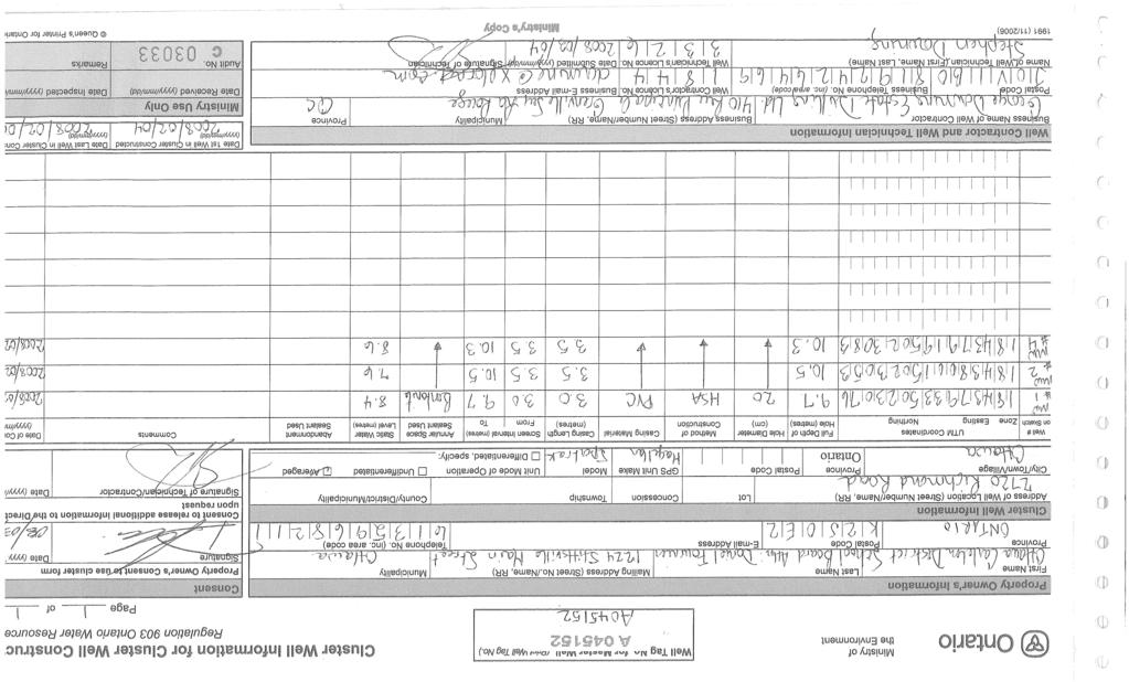
85