Construction of Rapid Sand Filters i) Media
|
|
|
- Nora Garrison
- 5 years ago
- Views:
Transcription
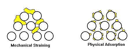
1 Filtration Process The flow of clarified water through a bed of granular media Purpose is to remove any particulate matter left over after flocculation and sedimentation Process operates based on 2 principles :- mechanical straining and physical adsorption Water fills the pores of the filter medium and impurities are adsorped on the surface of the grains or trapped in the openings
2
3 Types of Filters A Slow Sand Filters B Gravity Filters 1. Rapid Sand Filters 2. High Rate Filters - Dual Media - Multi Media C. Pressure Filters - Sand or Multi Media
4 Construction of Rapid Sand Filters i) Media Sand graded or homogeneous Generally 0.7 to 0.75m deep of mm fine sand (with eff size of 0.75mm, UC of <1.6) 0.1 m deep mm coarse sand 0.1m deep mm fine gravel 0.15 m deep of mm coarse sand
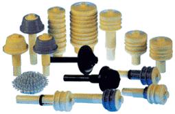
5 Construction of Sand Filters ii) Underdrain System Pipe lateral filter floor i. For separate air & water backwash Plenum filter floor i. For combined air & water backwash Nozzle slot size mm Nozzle density max 40 / m2


6 Pipe Lateral Filter Floor
7 Plenum Filter Floor
8
9 Construction of Sand Filters iii) Filter Configuration Number selected to minimise overloading of working filters when filters are taken off service for backwashing/service Ideally 6 nos, minimum 4 nos Size is limited by : i. Uniform collection of filtered water ii. iii. Even distribution of washwater & air Travel length of washwater to collection channel
10 Construction of Sand Filters iii) Filter Configuration (cont d) Normal size 25 to 100 m2 Length/breadth ratio of 1 to 4 Twice this size is possible with 2 beds separated by central washwater collection channel
11 Construction of Sand Filters iv) Filtration Rates Old filters 5 m/hr (m3/m2/hr) Newer design & dual media 10 to 15 m/hr However, recent concern over Cryptos and Giardia cysts had led to reduction to about 6 7 m/hr
12 Construction of Sand Filters v) Flow Control Constant rate variable head (equal flow distribution by inlet weir) Constant rate fixed head (submerged inlet; outlet valve is modulated) Delclining rate (not commonly used)
13 Filter Backwash Filters should be backwashed when the following conditions are met: Head loss is so high that filtration rate is below designed value Floc breaks through effluent turbidity increases Filter run reaches given hour of operation Filters taken out of service must be backwashed before putting back in service
14 Filter Backwash (cont d) When filter bed becomes clogged, head loss increased Designed head loss between 1.5 to 2.0m Traditionally, backwashing is by separate use of air and water, forcing them through sand bed by reverse flow Some design now uses air scour followed by air & water wash. A final water wash is sometime used
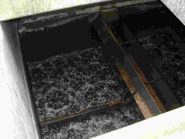
15 Filter Backwash (cont d) Air is introduced at a rate of m/min at a pressure of 0.42kg/cm2 Bed surface should show an even spreading of bursting air bubbles Air agitated sand breaks up surface scums & dirt is loosened from sand grain surfaces
16
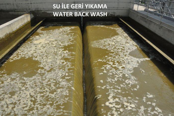
17 Filter Backwash (cont d) Water wash following air scour will expand & fluidise the bed Wash rate is about 0.5 m/min Pressure at nozzle outlet 0.6 kg/m2 Voids between grains increased & resulting rotation and attrition between grains produce scouring action to remove attached deposits Too high backwash rates result in loss of sand and waste of water & energy
18
19 Filter Backwash (cont d) Separate air & water wash i. Air scour for 3 4 minutes ii. Water wash for 4 6 minutes Combined air & water wash i. Air scour for 1 2 minutes ii. Air & water wash for 6 8 minutes iii. Water only rinse for 8 10 minutes Drain down time minutes Total period of washing minutes Total water consumption ~2.5 bed volumes
20 Filter Backwash (cont d) Sometimes difficult to remove all dirty backwash water before filter is returned to service Surface flush or cross wash is introduced Clarified water used to flow across top of filter bed from wall opposite the washout channel Included in backwash flow volume
21 Filter Backwash (cont d) Wash Launders Spaced at close intervals and perpendicular to washout channel Ensure launder bottom is above expanded bed surface Total period of washing minutes Saves backwash water volume but at slightly higher backwash head
22
23 Filter Backwash (cont d) Filter slow start After backwash, there s short period when filtrate turbidity is high Due to displacement of residual washwater with loosened solids, & lower solid removal efficiency of freshly washed media Remedy - either i. Send 1 st minutes of filtrate to waste or recyle stream ii. To allow time for filter to ripen by starting filtration at a slow rate
24 Filter Backwash (cont d) Water for backwash should be filtered & preferably chlorinated Best taken upstream of final ph correction to minimise risk of dissolving aluminum hydroxide floc retained in filter Volume of backwash water used is ~ 1-2.5% of plant throughput
25
26
27
28
29
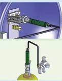
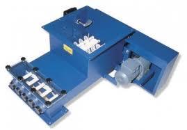
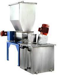
30 Chemicals Dosing Chemicals are added to water either as a solution, or in powder or slurry form Dry feeder A dry feeder incorporates a hopper which contains the powder and feeds a measuring device The device takes the form of a revolving table with a scraper of adjustable length or screw feeder Heaters are added to the hopper to prevent caking of poweder
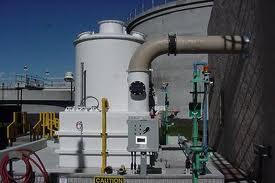
31 Chemicals Dosing (cont d) Solution feed The system comprise a storage tank for solution with correct strength; and a dosing rate-of-flow controller The tank holds 8 24 hrs supply and is often duplicated Many coagulants are corrosive so tanks are lined with acid resisting material (rubber, glass or special cement)
32
33 Chemicals Dosing (cont d) Solution feed (cont d) Dosing system being controlled manually or remotely For gravity feed dosers, rate can be altered by adjusting size of outlet orifice in a constant head tank For displacement pumps, rate can be altered by adjusting the length of piston stroke Most dosers are now automated, with the rate of flow dependent on the rate of flow of plant throughput

34 Plant Hydraulics First step in preparing a plant layout is to carry out hydraulic design Aim for gravity flow to avoid pumping Connections between various process units should be as short as possible A good hydraulic design will ensure efficient operation of treatment process
35 Plant Hydraulics (cont d) Calculation of head loss: Major & minor losses in pipes (Hazen William or Darcy-Weisbach formula) Losses through weirs Losses through openings Channel losses ( Manning formula ) Head loss through WTP generally 5 6 m
36 Plant Hydraulics (cont d) Location of treatment units should follow the natural hydraulic gradient to minimise cut & fill Ideally, site should have a gentle slope with difference in height of 6-8 m Where this is not possible, some process units have to be elevated (for flat ground) and modification of land conditions by cut & fill