Puu : Conventional and Non- Conventional Pulping as a Basis for Biorefinery (7 cr)
|
|
|
- Loreen Abigail Fields
- 5 years ago
- Views:
Transcription
 Lecture 13: Kraft pulping: Recovery of chemicals")
1 : Conventional and Non- Conventional Pulping as a Basis for Biorefinery (7 cr) Lecture 13: Kraft pulping: Recovery of chemicals and energy I
2 Learning Objectives After this lecture the student: understands, and is able to explain, the objectives of the kraft pulp mill recovery cycle and its sub processes can define the most important monitoring parameters of the recovery cycle (e.g. sulfidity, caustisation degree, reduction degree, dry solids content) and understands their importance recognises the chemical reactions taking place at different stages of the recovery cycle 2

3 Introduction to Chemical Recovery Processes 3
4 Introduction Explanation of what recovery department of a modern Pulp Mill does Recovery process of a modern pulp mill is based on best available techniques (BAT) Examples shown are typical equipment, but details are often vendor specific 4


5 Introduction Mills are planned to make production years and longer Some of the key machines in the mills have been almost the same for 50 to 60 years Continuous digester was developed in the -50 s Many equipment in this process were developed in the -80 s and -90 s Recovery boiler was developed in the -50 s DD washers were invented in 70 s and developed in the -80 s Rotary lime kiln was developed in the -50 s 5
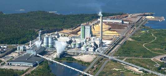

6 Introduction RAUMA MILL 6
7 Introduction Pulp mill products pulp softwood / hardwood energy steam and electricity crude tall oil turpentine biomass bark, wood residues lignin methanol Biorefinery 7
8 Pulp mill processes in a nutshell Woodyard Fiberline Pulp Drying Recovery Boiler Chemical Systems Evaporation Effluent treatment plant 8
9 Recovery cycle mission Recovery systems are the core component of a kraft pulp mill The three purposes of recovery systems are: regeneration of chemicals used in cooking production of steam for turbine and process destruction of waste streams generated elsewhere in the mill 9


10 Recovery cycle Evaporation Recovery boiler Causticizing Lime Kiln ** * 10


11 Recovery cycle 11
12 Terminology Weak black liquor is liquor from the brown stock washing, usually 14-20% ds Strong black liquor is high concentration liquor from the evaporation, usually > 50% ds Green liquor is solution from the recovery boiler containing chemicals mixed with water 12
13 Terminology White liquor is solution containing regenerated chemicals to be used in cooking Lime is a solid stream containing mainly CaO Lime mud is a solid stream containing mainly CaCO 3 13
14 Terminology Active sodium chemicals in the cooking process are referred to as alkali Total alkali represents all sodium compounds present in the liquor Active alkali represents those sodium compounds that are the main cooking agents Effective alkali is a term used to describe the relative strengths of sodium compounds as cooking agents e.g. in the case of sodium sulfide it is only half the amount of the substance that is effective in the cooking process 14
15 Terminology Total alkali: NaOH+Na 2 CO 3 +Na 2 S+Na 2 SO 4 or all Na-compounds Active alkali: Effective alkali: NaOH + Na 2 S NaOH + ½ Na 2 S Effect of K on these values? 15
16 Purpose of the recovery system The purpose of the recovery system is to return the inactive sodium compounds at the end of the cooking process into active compounds that can be reused at the beginning of the cooking process The active sodium compounds are in white liquor that comes from the causticizing plant The inactive sodium compounds are first introduced to the recovery system as part of the weak black liquor that is emitted from the cooking process 16
17 Black liquor Organics (including organic Na and S) Degraded lignin Isosaccharine acids Aliphatic acids Resin and fatty acids Polysaccharides Inorganics NaOH NaHS Na 2 CO 3 and K 2 CO 3 Na 2 SO 4 and K 2 SO 4 Na 2 S 2 O 3, Na 2 SO 3 and Na 2 S x NaCl Non process elements (Si, Al, Fe, Mn, Mg, etc.) % by weight Alén, kraft pulping of birch 17
18 Strong black liquor Concentrated to strong black liquor leaves the evaporation process at 85% dry solids Black liquor contains: water organic residue from pulping (that part of wood that does not end up as pulp) inorganic cooking chemicals (mostly spent) 18
19 Strong black liquor Na % K % S tot % Cl tot % S 2- % CO 3 % SO 3 % S 2 O 3 % SO 4 % C % H % N % HHV MJ/kgds Figures are given to show indicative magnitude of the various chemical compounds. 19

20 From black to green liquor Strong black liquor that comes from the evaporator fuels the recovery boiler Recovery boiler is also fuelled by a number of other sources (e.g. NCG, methanol, natural gas, heavy oil) Inorganics in black liquor form the smelt The smelt is dissolved into weak white liquor from the causticizing plant to produce green liquor 20

21 Recovery boiler smelt Carbonate melt (~70% Na 2 CO 3 ) dissolves all known materials when hot Ionic liquid low vapor pressure no viscosity no surface tension all components in ionic form 21
22 From green to white liquor The green liquor reacts with lime in the slaker to produce: lime mud white liquor The lime mud goes to the lime kiln where it is returned to lime The white liquor goes to the digester at the beginning of the cooking process completing the regeneration of the alkali compounds 22
23 Green liquor Raw Green Liquor (RGL) Raw material for white liquor Product of recovery boiler dissolving tank Composition: smelt from the boiler water (weak wash) Concentration is given g as Na 2 O/l or g as NaOH/l Main compounds as NaOH are: Na 2 S 40 g/l Na 2 CO g/l NaOH 10 g/l Na 2 SO 4 10 g/l Dregs 1500 mg/l Density 1.17 kg/l Definitions Total Titratable Alkali (TTA) Na 2 CO 3, Na 2 S and NaOH concentration typically g/l Dregs insoluble compounds in GL inorganics salts and unburnt black liquor Sulfidity Na 2 S/(NaOH + Na 2 S) 23
24 Terminology The efficiency of the process of regenerating black liquor (post cooking) to reusable white liquor (at the start of the cooking process) is measured by the ratio of active sodium cooking agents produced from the total amount of sodium compounds arriving into the recovery system This ratio can be monitored at various stages in the recovery process (some continuously and others by sample) 24
25 Terminology Causticizing efficiency: NaOH/(NaOH + Na 2 CO 3 ) Reduction efficiency: Na 2 S/(Na 2 S + Na 2 SO 4 ) or Na 2 S/S total Effect of K on these values? 25
26 Departments and streams MAJOR DEPARTMENTS Evaporation Recovery boiler Lime kiln Causticizing Turbogenerator NCG collection MINOR DEPARTMENTS Cl-K removal Condensate stripping Spill collection Methanol liquefaction Soap removal (with softwood) MAJOR STREAMS Weak black liquor Strong black liquor Smelt Green liquor White liquor Lime mud Lime DNCG +CNCG Water +Steam 26
27 Evaporation 27
28 Black liquor evaporation Black liquor recovered from pulping contains 14-17% dissolved solids These solids are composed of about 1/3 inorganic chemicals that were in the white liquor added to the digester The remaining 2/3 consist of the organic chemicals extracted from the wood Black liquor must be concentrated to above 60% solids so that it will burn without supplemental fuel 28
29 Basic process requirements Efficient use of energy Efficient separation of water vapor from black liquor Proper separation of methanol, tall oil soap Concentration of black liquor to 75-85% dry solids 29
30 Objectives of evaporator Use of BAT equipment Final black liquor concentration high enough to minimize SO 2 and TRS emissions Capacity large enough to accommodate spills High number of effects for energy efficiency 30

31 Evaporation Handling of Biosludge ClO 2 plant waste CTMP filtrates Closing mill s water circulation with secondary condensates Strengthening of black liquor Producing methanol fuel & CNCG & DNCG to incineration Producing Warm/District heating water Treating cooking and bleaching effluents Cl/K purge 31


32 Evaporation train 32
33 Evaporation Mission: Evaporation of weak black liquor to separate water and create a combustible product strong black liquor The three main processes that occur in the evaporator are: Black liquor + Heat Condensate + Steam Black liquor Strong Black liquor + Water + Steam Clean + Dirty condensate + NCG Black liquor + Soap (only softwood) 33

34 Evaporation 34
35 Evaporation process in general Evaporation plant carries out a number of simultaneous processes, which as well as producing strong black liquor for the recovery system, include: separation from the black liquor of: turpentine methanol soap (softwood production) production of clean condensate for mill use e.g. washing of lime mud 35
36 Evaporation capacity Typically expressed as ton H 2 O/h or kg H 2 O/s Evaporation capacity is determined by the heating surface area, available temperature drop and overall heat transfer coefficients 36

37 Basics of evaporation Heat Transfer Area Increasing black liquor dry solids with thermal energy Heat flow kw Heat Transfer coeff. Temp. diff. Over surface 37
38 Basics of evaporation Steam to next effect Tube wall Steam from previous effect Heat evaporates water (= steam) from black liquor Steam condenses releasing heat Drier black liquor is removed Condensates are removed 38

39 Basics of evaporation Multi effect evaporation (MEE), 6-7 effects 1 st effect uses primary LP & MP steam 2-7 effects use secondary vapor last effect vapor is condensed with cooling water in surface condenser evaporation done mainly by secondary vapor 39
40 Minimization of steam Evaporator processes should be undertaken in a way that maximizes the efficient use of energy e.g. as evaporation is done in stages, which allows 1 kg of steam to evaporate more than 7 kg of water 40

41 Basics of evaporation The more effects the better is the steam economy But the higher is the equipment cost 41
42 Modern evaporator train Seven+ effects for good steam economy Weak BL dry solids design 14 15% Strong BL dry solids >85% (with ash) Integrated stripper Possibility to handle biosludge Possibility to separate soap during softwood operation 10% additional capacity reserve to process spills Enclosed methanol treatment to minimize odor 42

43 Evaporation 43
44 Modern evaporator train WBL is flash cooled to effects 5, 6 & 7 Sweetened to 20% ds (softwood) Evaporated in effects 7, 6, 5, 4 & 3 heating surfaces Heated up with stripper gases between 3 & 2 effects Mixed with ESP ash before effect 1 Evaporated in effect 1 44

45 Modern evaporator train 45

46 Modern evaporator train 46
47 Condensates Condensates are liquids produced from vapor when they are cooled by condensation They comprise mainly of water clean condensates are formed when pure steam condenses foul condensates are formed when steam originating from black liquor is cooled 47
48 Foul condensate formation Each time black liquor is evaporated it forms steam that may be used at another stage When that steam is cooled it condenses to form a liquid that contains mainly water with some other substances that condense at the same temperature as water There are three main places in the pulp mill where foul condensates are formed: evaporation plant NCG handling in cooking 48
49 Foul condensate formation In each of these three cases the condensate contains TRS and volatile carbohydrates (e.g. methanol) and as a result the condensate has a level of odor depending the composition Cleaner condensate fractions are reused in parts of the mill processes that are not sensitive to slight contamination (e.g. pulp washing) All other foul condensate (smelly) streams are fed to the stripper where they are cleaned 49

50 Treatment of foul condensates Foul condensates contain methanol malodorous sulfur compounds turpentine red oil (eucalyptus only) water Steam is used in the stripper to remove contaminants Evaporator and stripper are integrated to get better heat economy located between effects 1 and 2 50
51 Treatment of foul condensates The higher is the condensate quality demand the more foul condensate is segregated the more stripping vapor is used the more stripper losses are generated foul condensate heating vapor losses to stripper of gas & trim condenser stripped condensate taken out hot The more expensive equipment 51
52 Effect of dry solids to NHV 15.0 NET HEATING VALUE, MJ/kg dry solids BLACK LIQUOR DRY SOLIDS, % 52

53 How to reach 80-85% dry solids? Due to the high viscosity MP-steam as heating medium liquor temperature 175 C in final concentrator Liquor retention time evaporator acts also as a LHT-reactor Duplex construction material high alkali content may cause Stress Corrosion Cracking (SCC) 53

54 BPR Boiling Point Rise Ref: Principles of black liquor evaporation, W J Frederik. 54
55 Liquor Heat Treatment (LHT) Liquor is heated to C Polysaccharide molecules are splitted Liquor viscosity degreases permanently Sulfur compounds & MeOH are generated Results depend on liquor type and effective alkali level 55
56 Evaporator types Thermal evaporation rising film evaporator falling film evaporator film inside the heating surface film outside the heating surface Forced circulation Direct contact evaporation Mechanical vapor recompression evaporation 56
 Liquor inside the tubes Steam outside the tubes Fouls with high solids liquor Sold as 3 7")
57 Falling film evaporator film inside tubes Gravity pulls liquor downwards (window during rain principle) Liquor inside the tubes Steam outside the tubes Fouls with high solids liquor Sold as 3 7 effect 57

58 Falling film evaporator film outside tubes Gravity pulls liquor downwards (window during rain principle) Liquor outside the tubes Steam inside the tubes Used with high solids liquor Sold as 1-3 effect and as concentrator 58
59 Forced circulation evaporator Pump forces liquor through heat exchanger Liquor inside the tubes Steam outside the tubes Used with high solids liquor Sold as 1-3 effect and as concentrator 59


60 Lamella type evaporator Steam flow Liquor film flowing downwards Heat surface 60
61 Evaporator scaling Soap and tall oil scaling soap sticks to the surface soap carries fibre and calcium most of tall oil soap separates at 25-30%ds Lignin scaling precipitation at ph < 11 61


62 Evaporator scaling Falling film lamella Resistant to scaling Self-cleaning Tolerates even nonsoluble scaling Tube evaporator Plugging under severe scaling conditions Non-soluble scaling requires mechanical or chemical cleaning 62
63 Typical process challenges PROBLEM SOLUTION HEAT TRANSFER SURFACE SCALING Low alkali (lignin precipitation) High soap & fiber content High Ca, Si, Al concentrations FOAMING IN BACK END EFFECTS Low ds-% POOR CONDENSATE QUALITY Too much MeOH in WBL If color in condensate, caused by too high evaporation rate & carry over If just smell & high COD, improper segregation of VOC s Liquor or fibers in fiber line foul condensate HIGH DRY SOLIDS ds%, should be as high as possible, however this causes some special arrangements High viscosity Fouling Poor heat transfer Corrosion (high Effective Alkali) Ash mixing Wash sequences Soap skimming Calcium deactivation reactor Liquor heat treatment (LHT) Sweetening of WBL to over 20 % Low secondary vapor velocities in shell Droplet separators Proper segregation in lamellas Dedicated condensation packages Duct stripper High 1 st effect temp (MP-steam) High circulation rate in 1 st effect Liquor heat treatment (LHT) Ash mixing Wash sequences Duplex in HD-concentrator 63
64 CNCG & DNCG sources and destinations CNCG DNCG & Power boiler 64 64
65 Recovery Boiler 65
 to")

66 Purpose of the recovery boiler Recovery of Chemicals = Chemical Reactor recovery of chemicals from the black liquor through combustion (reduction) to be used for cooking chemical preparation Recovery of Energy = Steam Boiler burn the organic materials in the black liquor and produce energy (steam, electricity) 66
67 Modern recovery boiler Steam pressure > 100 bar Steam temperature > 500 C Capacity > tds/d Dry solids content > 80 % Combustion air from several levels DNCG combustion (Diluted gases) Additional fuels CNCG (strong gases) methanol turpentine biosludge soap 67
68 Natural circulation Steam Drum Downcomer Furnace tubes Steam bubbles Heat Driving force is static pressure difference between water in downcomers and watersteam mixture (emulsion) in furnace tubes P losses = (ρ water - ρ mixture ) g h Pressure increase reduces driving force Heat to tubes by radiation and convection 68


69 Natural circulation Water flows downwards to furnace bottom and boiler bank 2 Water steam mixture rises up in furnace wall tubes and in boiler bank panels 3 Water steam mixture flows to the drum where water and steam are separated 69
 5. Steam drum 6. Boiler generating bank 7. Economizers 1 and 2 8. Rearwall screen 9. Furnace screen 10. Ash hoppers (3 pcs.) 11. Feedwater tank 12. Ash conveyors 13. Downcomers 14.")
70 Recovery boiler main parts 1. Superheaters (1B, 2, 3, 4, 1A) 2. Bullnose/nose arch 3. Black liquor nozzle openings 4. Start-up burners (*) 5. Steam drum 6. Boiler generating bank 7. Economizers 1 and 2 8. Rearwall screen 9. Furnace screen 10. Ash hoppers (3 pcs.) 11. Feedwater tank 12. Ash conveyors 13. Downcomers 14. NCG ducts 15. Tertiary air ducts 16. Secondary air ducts 17. Primary air ducts 18. Smelt spouts 19. Dissolving tank 20. Mixing tank (*) Electrostatic precipitator 70
71 Furnace process Black liquor is injected into the recovery boiler from a height of 5 8 meters Combustion air is injected at three different zones in the boiler Burning black liquor forms the char bed at the bottom of the boiler, where complicated reactions occur Smelt is drained from the boiler and is dissolved with weak white liquor to form green liquor, which contains the recovered cooking chemicals High pressure steam is generated from feed water by heat releasing from combustion reactions Tertiary air Black liquor nozzles Upper secondary air Lower secondary air Primary air Smelt 71 XT Training

72 Chemical reactions in furnace Drying water is evaporated Devolatilization droplet size increases gases are released Char burning carbon is burned off inorganic salts melt, reactions Upper furnace reactions volatiles combustion formation of sodium sulphate and sodium carbonate 72

73 Black liquor droplet burning 73


74 Liquor spraying Target spray the liquor evenly on the charbed optimize the droplet size Liquor gun openings on all walls Locations adjusted to the air system between secondary and tertiary air ports Tertiary air Firing liquor Secondary air 74 XT Training
75 Smelt and green liquor Smelt is molten inorganic chemicals produced in the reducing zone of furnace Sodium carbonate Na 2 CO 3 (65 75 %) Sodium sulfide Na 2 S (20 25 %) Sodium sulfate Na 2 SO 4 (2 3 %) Green liquor is a mixture of smelt from RB and Weak White Liquor from Causticizing Plant temperature at dissolving tank outlet C dregs content (unburned carbon) mg/l reduction efficiency (in smelt): % Na 2 S/(Na 2 S + Na 2 SO 4 ) increasing reduction efficiency decreases steam production 75 XT Training

76 Smelt-water explosion Even a small amount of water mixed with molten smelt at high temperature can cause it purely physical phenomenon Water turns into steam in few ms sudden evaporation causes increase of volume and a pressure wave of Pa sufficient to cause furnace walls to bend Furnace equipped with a weak corner to control the direction of explosion 76


77 Recovery boiler process 77 XT Training
78 Useful numbers ADt (bleached) tds Dry solids (virgin) % Density kg/l HHV MJ/kgds Furnace bottom loading tds/d/m MW/m 2 Steam production kg/kgds 78

79 Effects of dry solids + Steam generation increases (less water to the furnace) + Less flue gases + Lower SO 2 emissions Steam flow / kg / s Less desuperheating more heating surface - Viscosity increases black liquor flashing, fouling Dry Solids / % 79
80 White Liquor Plant 80


81 Modern white liquor plant Lime Dryer Make-up Limestone Silo Lime Flash Dryer Lime Kiln White liquor preparation Lime Cooling Burnt Lime Bin Green Liquor Storage Tank Raw Green Liquor Storage Tank Green Liquor Cooler Electrostatic Precipitator Lime Mud Storage Tank White Liquor Storage Tank Weak White Liquor Storage Tank Lime Slaker White liquor filtration Green liquor filtration Lime Free dregs handling 81
82 Recausticizing Mission: Production of white liquor for cooking by converting sodium carbonate to hydroxide with lime and removal of non process elements Smelt Dregs Grits Lime This image is indicative only and does not purport to show all features of AMT technology. 82
83 Terminology Green liquor dregs are solids separated from green liquor by filtration Slaker grits are solids separated during lime addition Burnt lime is a solid stream from lime kiln containing mainly CaO Make-up lime is an incoming solid stream containing mainly CaO 83
84 Recausticizing The three main processes that occur in recausticizing are: CaO + H 2 O Ca(OH) 2 Na 2 CO 3 + Ca(OH) + 2 2NaOH CaCO 3 solids in liquor solids + liquor 84
85 Recausticizing There are three processes undertaken in the recausticizing stage: cooking liquor is produced from green liquor by adding slaked lime which produces white liquor and lime mud (calcium carbonate) lime mud (calcium carbonate) is fed into lime kiln to produce lime process residue is purged as dregs and grits 85
86 Recausticizing unit operations Smelt dissolving tank (in RB area) molten smelt from recovery boiler and weak white liquor are mixed to produce green liquor Raw green liquor stabilization tank variations in green liquor composition are reduced by sufficient retention time Green liquor filtration particles in green liquor removed by filtration 86
87 Recausticizing unit operations Slaker lime and green liquor are mixed to produce white liquor Causticizers three or more agitated tanks in series are used to ensure as complete a reaction as possible White liquor filtration lime mud is separated from white liquor by filtration 87
88 Recausticizing Process LimeMilk LimeFree 88 88


89 Green liquor handling Raw green liquor Filtrated green liquor Dregs 89
90 Green liquor Na K S tot Cl tot S 2- NaOH Na 2 S Na 2 CO 3 Na 2 SO 3 Na 2 S 2 O 3 Na 2 SO 4 Total alkali Active alkali Effective alkali g/kgds g/kgds g/kgds g/kgds g/kgds g/kgds g/kgds g/kgds g/kgds g/kgds g/kgds g NaOH/l g NaOH/l g NaOH/l Figures are given to show indicative magnitude of the various chemical compounds. 90
91 White liquor definitions and reactions White Liquor (WL) Definitions Reactions Containing small amount Suspended Solids (SS) < 20 mg/l Concentration is given g as Na 2 O/liter or g as NaOH/liter Main compounds as NaOH are: Na 2 S 40 g/l Na 2 CO 3 20 g/l NaOH 100 g/l Na 2 SO 4 10 g/l Suspended Solids < 20 mg/l Active Alkali (AA) NaOH + Na 2 S WSA (Water Soluble Alkali) Soluble Na as Na 2 O Causticizing Degree (CE) NaOH/(NaOH + Na 2 CO 3 ) Suspended Solids (SS) Compound insoluble in WL Typically measured after White Liquor filter Concentration < 20 mg/l, mainly CaCO 3 Lime Lime Kiln product or make-up lime Mainly CaO > 90% Lime Milk GL + Lime Lime slaking CaO + H 2 O Ca(OH) kj/kg CaO Causticizing reaction Ca(OH) 2 + Na 2 CO 3 2 NaOH + CaCO
92 Green liquor filtration Green liquor contains ppm of impurities called dregs Impurities originate from raw material sources, primarily wood chips Dregs contain almost all the minerals in the wood 92
93 Green liquor filtration Dregs only place where these minerals are removed Often separate stabilization tank to minimize variations in density temperature flow Storage after filtration 93
94 Process steps Once green liquor is produced to a stabilized concentration it is mixed with lime and the slaking process commences The lime reacts with the water in the green liquor producing slaked lime Slaking occurs in a short time Slaked lime then reacts with sodium carbonate in the green liquor to lime mud and sodium hydroxide (white liquor) 94
95 Process steps This second reaction is called causticizing and occurs in the causticizing tanks, long residence time needed to complete reactions The lime mud goes to the lime kiln to produce lime The white liquor is then used in the digester 95

96 Slaking chemistry 96
97 Causticizing chemistry Slaking kj/kg CaO CaO (s) + H 2 O (aq) Ca(OH) 2 (s) Causticizing -560 kj/kg CaO Ca(OH) 2 (s) + Na 2 CO 3 (aq) 2NaOH (aq) + CaCO 3 (s) 97
98 Dregs washing 3-8 % of suspended solids in green liquor Sodium recovery Drum filter with precoat coating with lime mud of mm thick dry solids % 98
99 White liquor Final product from causticizing system Cooking chemical to the digester Active ingredients NaOH and Na 2 S 99
100 White liquor analysis Na K S tot Cl tot S 2- NaOH Na 2 S Na 2 CO 3 Na 2 SO 3 Na 2 S 2 O 3 Na 2 SO 4 Total alkali Active alkali Effective alkali g/kgds g/kgds g/kgds g/kgds g/kgds g/kgds g/kgds g/kgds g/kgds g/kgds g/kgds gnaoh/l gnaoh/l gnaoh/l Analysis is given to show indicative magnitude of various chemical compounds 100
101 Objective of causticizing High active alkali concentration high causticity high reduction Clean white liquor to minimize chemical consumption Efficient lime mud washing 101
102 Causticizing in modern mill White liquor active alkali (NaOH) g/l 136 White liquor sulfidity % 32 Causticity % 82 Reduction efficiency % 95 Green liquor filtration White liquor filtration Capacity m 3 WL/d >
103 Lime kiln The two main processes that occur in lime kiln are: Lime mud + Heat CaCO 3 + vapor CaCO 3 + Heat CaO + CO 2 103

104 Lime kiln Mission Converting used lime mud into lime 104
105 Lime product quality Ideal reburnt lime forms soft pebbles of approx. 2 cm in diameter pebbles Reburnt lime quality is judged in terms of: availability - refers to the fraction of lime (as CaO) in the reburnt lime product residual calcium carbonate reactivity particle size 105
106 Lime product quality Fresh lime Reburnt Soft Hard Density, kg/l 1.6 >2,2 1,7-2.1 Porosity, % 50 < Surface area, m 2 /g >1.0 <0,3 0,21-0,43 Reactivity, o C/min >10 <2 low From Adams,
107 Lime kiln fuels Natural gas Fuel oil Hydrogen (from chemical plant) Odorous gases (option) Methanol (option, methanol burning decreases CO 2 from mill) Gasification gas Saw dust Lignin 107
108 Lime kiln Lime mud + heat burned lime + carbon dioxide Adiabatic flame temperature 1750 C CO 2 Fuel: Oil, Gas, CNCG s CaCO 3 CaO 108
109 Energy balance MJ/t CaO Water heating & evaporation Energy in kiln product and dust 140 Enthalpy of calcination Enthalpy in CO 2 from calcination 90 Enthalpy of combustion products 410 Radiation loss 820 Total input


110 Pulp mill processes in a nutshell Woodyard Fiberline Pulp Drying Recovery Boiler Chemical Systems Evaporation Effluent treatment plant 110