Calculation of Water Activity in Point 7
|
|
|
- Blaise Bridges
- 5 years ago
- Views:
Transcription

1 Calculation of Water Activity in Point 7 SC/RP, M. Brugger, S. Roesler joachim.vollaire@cern.ch Calculation of Water Activity in Point 7
2 Production of radioactive nuclei in water Production on Oxygen atom (H 2 O) Half Life Decay modes and energy 3 H y 100 % β -,E ave = 5.68x10⁻³ MeV 7 Be 11 C 14 C 13 N 53.3 d 20.4 m 5730 y 9.97 m 89.7 % β +, Electron capture 10.3 % γ, E ave = MeV 99.8 % β +,E ave = 3.86x10⁻¹ MeV 100 % β +,E ave = 4.95x10⁻² MeV 99.8 % β +,E ave = 4.92x10⁻¹ MeV - Trace elements can lead to the production of other nuclei as 24 Na 14 O 15 O 71 s 122 s 99.9 % β +,E max = 1.81 MeV 0.6 % β +,E max = 4.12 MeV 99 % γ, E = MeV 99.9 % β +,E ave = 7.35x10⁻¹ MeV - Most critical nuclei are 3 H and 7 Be - 7 Be has a specific behaviour (filters)
3 Release of radioactive water / CERN policy To consider effluents as radioactive two conditions must be fulfilled : 1 The specific activity (Bq/Kg) exceeds 1% oftheexemption limit 2 The absolute activity released exceeds 100 times the absolute exemption limit LE abs expressed in Bq For mixture : 1 A L i i i Based on Swiss Legislation but could be accepted by french authorities for the LHC operation (INB) 3 H 7 Be Specific activity (Bq/kg) 6.0x10 03 Absolute activity (Bq) 6.0x x x10 07 Exemption limit (LE) : 3 H : 6x10 5 Bq/kg 7 Be : 4x10 5 Bq/kg In any case in Points 6,7 and 8 authorisation from the environmental section is required due to the low flow rate of the receiving streams Authorising releases of radioactive water into the environment, P. Vojtyla (EDMS )
4 Different water pipe in the tunnel in Point 7 Tunnel Cross Section in Point 7 Raw water supply DN 200 Raw water return DN 250 Central Drain DN 300 Demineralised Water return DN 100 Demineralised Water supply DN 100 Water Filling DN 65 Chilled water return DN 65 Chilled water supply DN 65 FLUKA used for the calculations - Demineralised water circuit (supply and return) - Chilled water circuit (supply and return) - Water Filling pipe - Raw water supply pipe - Raw water reject pipe - Drain pipe The presentation will focus on - Circuits Description - Activity calculation - Release scheme
 Irradiation of water sample samples copper target 1.")

5 Water benchmark experiment at CERF Validity of FLUKA for water activation calculation in the LHC? SPS secondary pulsed beam, 120 GeV (1/3 protons, 2/3 pions, 1.5 % kaons) Irradiation of water sample samples copper target 1. Treated Water 2. Demineralised water 3. Infiltration water 4. Raw Water Simulation of the experimental setup Beam characteristics measurement Detailed Chemical Analysis Comparison FLUKA / experiment Gamma spectroscopy measurement using a Germanium detector and 3 H activity determination with a liquid scintillation counter
6 Results from the chemical analysis PA3 Appoint Deconc. Distilled H 1.12E E E E+01 O 8.88E E E E+01 C 4.08E E E-02 N 5.90E-05 SiO E E E-04 Si 1.18E-04 Ca 6.90E E E-03 Mg 5.20E E E-03 Sr 1.80E-05 Na 2.13E E E-03 K 4.60E E E-04 Li 2.00E-03 Fe 2.00E E E-04 Zn 1.00E E E-04 Cl 1.00E E E-03 SO E E E-03 F 2.60E-05 Exact composition taken into account in the FLUKA calculation Different traces element composition for the different samples Nuclei production on trace elements can be benchmarked
7 Treated Water Demineralised Raw water Infiltration Average Results of the benchmark experiment Ratio Measurement / Simulation 24 Na 3 H 7 Be 1.16(9.8%) 2.45(4.1%) 1.00(9.8%) (4.1%) (15%) 2.52(4.1%) 1.10(15%) 1.02(38%) 2.69(4.1%) 1.09(9.8%) 1.11(23%) 2.54(4.1%) 1.07(8.1%) - FLUKA underestimates the 3 H production - Excellent agreement for 24 Na and 7 Be Are those results valid for LHC calculation? Simulated fluence in a water bottle and in one of the LHC water pipe correction factor will be applied to LHC calculation for 3 H Fluence [arb. u.] CERF Neutrons CERF LHC Protons Neutrons LHC Protons CERF π Energy[GeV] LHC π +
8 Calculation of residual nuclei production with FLUKA FLUKA geometry used for air activation (M.Brugger) Small changes - Air duct removed - New pipe locations Characteristics - 2x2 Bending magnets - 2x12 Quadrupoles magnets - 1x3 Primary collimators - 1x11 Secondary collimators Bending Magnets Quadrupole magnets Quadrupole magnets Quadrupole magnets Quadrupole magnets Primary collimators Secondary collimators Secondary collimators Secondary collimators Secondary collimators
9 The Demineralised Water Circuit - Two different circuits supply Point 7 with demineralised water - Used to cool several equipments such as collimator, warm magnets... - To empty the DW circuits the central drain is used (oil in Point 7&8) Point 8 Point 6 Point 7 10 m 3 65 m 3 Nant Cobe 10 m 3 Nant Marquet 180 m 3 /h SECTOR 7-8 Q = 197 m 3 /h V = m 3 P = 16 bar 30 m 3 /h SECTOR 6-7 Q = 156 m 3 /h V = m 3 P = 16 bar UW UW65 PUMPS EXPANSION VESSEL DEMINERALISER UX m 3 70 m 3 /h 11 m 3 Lowest Point 11 m 3 manual valves Natural flow of the drain

10 Equipments cooled with demineralised water - Water present in the pipe (2xDN100) and used to cool equipments - Each device are connected to the supply and return pipes (in the simulation) Y cm Carbonjaws C opper Steel tank Water Xcm Y cm Steel yoke Xcm Y cm Collimator Quadrupole Dipole Water Air gap Steel yoke Water Xcm - The demineralised water is closed to the beam, radioactive nuclei are produced in the main pipes and in the equipments (Collimation project web site)
11 The Demineralised Water Circuit - Simulation length equal to 500 m, particle which are able to induce radioactive nuclei are transported within the length of the simulation Collimator Quadrupole Dipole Entirecircuit Real Volume Simulated Volume Flexible hose Volume 1 l 1.5 l 3.9 l 30 l 20 l 3.3 l 20 l 30 l 3.4 l 50 m l Individual connections volumes are indicated for one module 500 m Radioactive nuclei production per lost protons and per volume units Normalisation to the real volume
 6.3x10-01 2.9x10-02 4.9x10-02 7 Be nuclei/p 9.7x10-02 5.1x10-02 1.7x10-01 2.1x10-02 9.8x10-01 1.2x10-01 7.0x10-02 1.6x10-02 2.2x10-03 4.8x10-03 6.")
12 Supply Pipe (1) 1.6x x rd Primary(2) 1.4x x st Dipoles(3) Some results for 3 H and 7 Be production 3 H 7 Be 3 H nuclei/l/p nuclei/l/p nuclei/p 1 st Secondary(4) 4.9x x st Quadrupole(5) 6.3x x x Be nuclei/p 9.7x x x x x x x x x x x10-02 Y cm Dipole magnets Primary collimators Quadrupoles magnets 5 Secondary collimators Concrete floor Xcm HadronsFluence[arb. units] - Supply and return pipes do not have the main contribution - Activation occurs in the equipment Hadronsfluencemap
13 Production of radioactive nuclei per lost protons Main Pipes H nuclei/p Activity calculatin for 3 H and 7 Be 7 Be nuclei/p 0.20 All Collimators All Dipoles All Quadrupoles Total Be concentration is close to saturation - 7 Be will be caught in the ions exchangers - 3 H concentration will double if the water is used for two years A i = Activity Calculation Y i N t irr p ( exp( λ t )) 1 i irr Y i nuclei per lost protons N p protons lost during the time t irr λ i decay constant of nuclei i Losses Ultimate 3.0x10 16 p/beam Nominal Irradiation 180 days Specific Activity a i = V 1.9x10 16 p/beam
14 Activity of 3 H and 7 Be Swiss legislation : 3 H 7 Be Specific activity (kbq/kg) 6.0 Absolute activity (MBq) two conditions must be fulfilled at the same time to consider water as radioactive Ultimate Losses and one year of operation Tritium activity * 7 Be activity * = MBq - a i = kbq/l - = MBq - a i = kbq/l - Nominal Losses and one year of operation Tritium activity * 7 Be activity * = MBq - a i = kbq/l - = MBq - a i = kbq/l - Production Yield corresponding to phase 1 collimator! Total volume of the circuit = 2 x 50 m 3 7 Be concentration calculated without taking into account the effect of the filters * Statistical uncertainty
15 What to do with this water? - Possibility to take samples in the UW cavern an purge the circuit before the activity level becomes critical (CERN detection limit of the order of a few Bq/l) - Water can only be brought back to the surface after being mixed with the so called clean water (lot of hydrocarbons) - Partly open decantation basin at the surface for hydrocarbons/water separation / other solutions being discussed (truck, no big stream...) Point 8 Point 6 Point 7 10 m 3 65 m 3 Nant Cobe 10 m 3 Nant Marquet 180 m 3 /h 30 m 3 /h UW UW65 PUMPS EXPANSION VESSEL DEMINERALISER UX m 3 70 m 3 /h 11 m 3 11 m 3 manual valves Natural flow of the drain

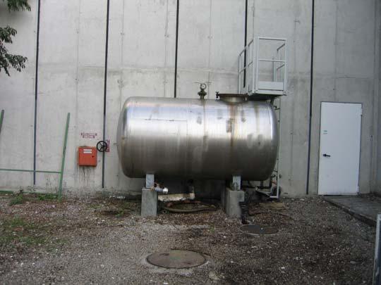
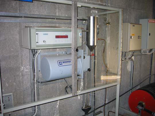
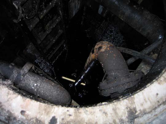
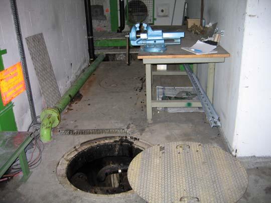
16 A few pictures
17 Chilled Water Circuit Chilled water return DN 65 Chilled water supply DN 65 SU Building Production Chilled Water circuit in beam cleaning insertion (point 7) DN 100 DN m PM m 207 m RR 73 TZ 76 UJ m Ventilation doors RR 77 - Closed circuit used to cool ventilation convectors - Dilution at the surface : big tank of 30 m 3 + other circuits used for air handling 60 m 3 - Radioactive water expected in the surface buildings - Circuit equipped with filter Should catch 7 Be

18 Radioactive nuclei production 3 H : Supply + Return pipes 0.56 nuclei/p 7 Be : Supply + Return pipes nuclei/p Nominal Losses and one year of operation Tritium activity * 7 Be activity * =37+1MBq - a i = kbq/l - Chilled Water Circuit = MBq - a i = kbq/l - Ultimate Losses and one year of operation Tritium activity * 7 Be activity * =59+2MBq - a i = kbq/l - =275+13MBq - a i = kbq/l - circuit volume is m 3 Chilled and mixed water Engineering Specifications LHC Project Document No. LHC-FG-ES-0001 rev 1.0 Page 16 of 22 3 H : 6 kbq/l 7 Be : 4 kbq/l Specific activity Figure 13. Production and distribution of chilled water at LHC point 7
19 Raw Water Circuit Beam cleaning Raw water return Raw water supply 45 m 3 /h 45 m 3 /h 60 m 3 /h 3 30 m 3 /h 30 m 3 /h 2 60 m 3 /h m 3 /h RE m 3 /h 150 m 3 /h 5 1 BA6 60 m 3 /h 100 m 3 /h 175 m 3 /h 8 Release Nant d'avril 250 m 3 /h 15 m 3 /h 6 60 m 3 /h 30 m 3 /h 7 30 m 3 /h - Open circuit, the water flows once in the collimator area - Reject pipe collects water from the cooling towers - Two circuits join in Point 1 before the release in the Nant d'avril - Estimate of the flow rate gives the time of irradiation in the collimator area
20 - Pipes located in the concrete (shielding) Raw Water Circuit Activity Specific activity in several locations Production of radioactive nuclei 3 H supply pipe : 0.5 nuclei/proton 3 H Return pipe : 0.2 nuclei/proton 7 Be supply pipe : 0.08 nuclei/proton 7 Be return pipe : 0.03 nuclei/proton Raw water return DN 250 Central Drain DN 300 Raw water supply DN 200 Rejected in the Nant d'avril in 180 days 98 MBq of 3 H 1290 MBq of 7 Be Supply Pipe Before IR7 Point 7 End of IR7 Reject Pipe 3 H (kbq/l) 7 Be (kbq/l) 3.96x x x x x x10-3 Before IR7 Point 7 (1) Point 7 (2) 1.71x x x x x x10-3 End of IR7 3.38x x10-3 Nant d'avril 1.09x x Contribution from beam-gas interactions before the collimators section - Junction with the second circuit in Point 1 before release 3 H : 6 kbq/l 7 Be : 4 kbq/l
21 Water Filling Pipe - This pipe is used to supply the demineralised water circuits in each octant with demineralised water produced in Point 1 - It is hard to evaluate the flow rate in the pipe and thus the time spend by water in the collimator area. However the total activity produced can be estimated Central Drain DN 300 water filling Raw water return DN 250 Raw water supply DN 200 Nominal Losses and one year of operation Tritium activity 7 Be activity =17+1MBq - =76+5MBq - Ultimate Losses and one year of operation Tritium activity =31+1MBq - 7 Be activity = MBq 3 H : 0.3 nuclei produced per lost protons in the collimators 7 Be : 0.04 nuclei produced per lost protons in the collimators
22 Synthesis of tritium concentration and releases The specific and total activity calculated correspond to losses for the ultimate intensity of the accelerator Release Point Specific activity kbq/l Estimated volume Total activity (MBq) Comments Nant d'avril (BA6) 1.09x m 3 /h 98 Raw water circuit including the two half rings with contribution from collimators in point 3 and 7. The average flow in BA6 is supposed to be equal to 250m 3 /h Nant Marquet (Pt7) 7 50 m The activation results from 180 days of operation of the accelerator, it is then assumed that the water is replaced. The water must be mixed with other drainage water before it can be pumped-up to the surface Nant Marquet (Pt7) m 3 This is the activity reached after 180 days of operation for the water of this circuits which also flows in surface buildings Nant de cobe (Pt8) 7 50 m The activation results from 180 days of operation of the accelerator, it is then assumed that the water is replaced. The water must be mixed with other drainage water before it can be pumped-up to the surface
23 Perspectives - Updated layout : flexible, long primary collimators, absorbers (water cooled?) Conclusions - The activity in the demineralised water circuit may reach values close to legal limits (if the principles of the Swiss legislation is accepted by French authorities) - There are no big streams in Point 7 and in Point 8 to receive those large amount of water hard to estimate the effect of this release - The tritium activity in the water is several hundred times higher than the activity of rain water (few Bq/l)