Site Investigation MUHAMMAD AZRIL HEZMI
|
|
|
- Joan Chambers
- 5 years ago
- Views:
Transcription
1 Site Investigation MUHAMMAD AZRIL HEZMI
2 Definition Essential part of the preliminary design workon any important structure in order to provide adequateand reliable geotechnical informationand site condition, so that a safe, practicaland economical design can be carried out.
3 Main objectives To assess the general suitability of the site for the proposed works, including implications of previous use or contamination. To enable an adequate and economic design to be prepared, including the design of temporary works. To plan the best method of construction, including foreseeing and providing against difficulties and delays that may arise during construction due to ground and other local conditions. To determine the changes that may arise in the ground and environmental conditions, either naturally or as a result of the works. To advise on the relative suitability of differences sites, where alternatives exist.
4 Stages Desk study / Site reconnaissance Ground Investigation Monitoring
5 Desk study Involves collecting existing informationabout the site and put it all together to build a conceptual model of the site. Information gathered at the desk study stage are: Topographical maps Geological maps Soil survey maps Aerial photographs Details of existing development Site history Local authority information Utilities Ownership of adjacent property Existing site investigation reports


6 Desk study
7 Site reconnaissance An early examinationof the site by geologist, land surveyor and engineer to give an idea of the work that will be required. Information collected on site reconnaissance are: Overall site layout Surface conditions Detail of access and nearest road Surrounding site condition Existing nearest utilities (pipe, electricity) Climates and hazards (rainfall, flood, contamination) Geographical information (plants, river) Obstacles and restrictions
8 Ground investigation Investigation of detailed geology and subsurface soil conditions. The principal objects of the detailed soil survey are as follows: Determine detail geological structure including thickness and sequence of the strata Determine ground water conditions To carry out in situ testing To obtain disturbed and undisturbed samples for laboratory testing

9 Ground investigation Boring Site exploration methods: Test or trial pits Simple hole dug in the ground (1m 3m) that large enough for a ladder to be inserted either dug by hand or mechanical excavator, thus permitting a close examination of the sides.
10 Ground investigation Boring Hand auger The hand auger (attached to drill rods and turned by hand) is often used in soft soils for borings about 6m.
11 Ground investigation Boring Boring rig Common types of borings are auger borings, wash borings and core borings. Auger boringsis a screw like tool used to bore a hole in 30 m depth. Removed soil can be used for field classification and laboratory testing.
12 Ground investigation Boring Wash borings consist either driving casing or chopping and jetting. For driving casing method, boring rig consists of dropping the cutter (1.5m 3m above the soil) with the soil sampler and is largely carried out by hand and when site conditions are suitable the operation is often powered.
13 Ground investigation Boring For chopping and jetting method, the boring consists simultaneous drilling and jetting action. The soil is loosened by a high pressure water jet from a pipe passing down the borehole. Returning water transports soil to the ground surface, where samples can be collected for examination and classification.
14 Ground investigation Boring Core borings are commonly used to drill into and through rock formations. Core borings are performed using a core barrel, a hardened steel or steel alloy tube with a hard cutting bit containing tungsten carbide or commercial diamond chips by rotating (speed 600 rpm 1200 rpm) them with a drill. Core barrels are typically 5 cm 10 cm in diameter and 60 cm to 300 cm long.
15 Example 1 A 1.25 m square footing is subjected to a contact pressure of 300 kn/m 2. The unit weight of the cohesive soil supporting the footing is 18.5 kn/m 2 and groundwater is known to be at a great depth. Determine the minimum depth of boring that should be carried out in the site

16 Solution Assume that the minimum depth of boring = z Overburden pressure at depth z, σ = 18.5 x z kn/m 2 Using 1:2 stress distribution, the increase in stress at depth z
17 Table to determine minimum depth of borings based on 10% of the overburden pressure
18 Table to determine minimum depth of borings based on 10% of the overburden pressure

19 Table to determine minimum depth of borings based on 10% of the overburden pressure
20 Example 2 Given: 1. An 8ft square footing is subjected to a contact pressure of 4000 lb/ft The wet unit weight of the soil supporting the footing is estimated to be 120 lb/ft The water table is estimated to be 30 ftbeneath the footing Required: The minimimdepth of test boring by referring Table Barsdaleand Schreiber, 1979.
21 Solution Refer figure 3-7; Minimum depth of test boring is determined to be 22ft
22 Ground investigation Sampling Disturbed sample These samples are easy to getand can be taken whenever a change of soil type observed. The soil is remoldedand generally required for identification testing. Disturbed sample are usually collected in airtight tins, plastic jars or plastic sampling bags and securely labeled. Undisturbed sample These samples may be collected by several methods. If a test pits is available in clay soil, an undisturbed sample may be obtained by simply carving a sample very carefullyout of the side of the test pit. Such a sample should then be coated with paraffin wax and placed in an airtight container.
23 Ground investigation Sampling A more common method of obtaining an undisturbed sample is to push a tube into the soil, thereby trapping the sample inside the tube. The soil samplerusually uses 50 mm, 76 mm and 100 mm in diameter with maximum depth of 60 m. The ends of the tube should be sealed with paraffin wax immediately after the sample is brought to the ground surface. It is virtually impossible to obtain totally undisturbed samples, but it assumes the soil is undisturbed samples when the area ratio, A r should not exceed 20%.
24 Ground investigation Sampling A r = (D w2 D c2 )/ D c2 x 100 Where; A r = Area ratio D w2 = External diameter D 2 c = Internal diameter
25 Ground investigation Sampling Standpipes Insert an open ended tube, usually 50 mm in diameter and perforated at its end, into the borehole. The tube is packed around with gravel and sealed with clay and backfilled to prevent access to rainwater. Observations must be taken for several weeks until equilibrium is achieved.
 or a close system (cohesive soil).")
26 Ground investigation Sampling Piezometers The piezometers can exist as an open system (cohesionless soil) or a close system (cohesive soil). The pressure is measured by an electrical transducer.
27 Ground investigation Sampling Seismic refraction This method involves generating a sound waveusing a falling weight or small explosive charge and then recording its reception at a series of geophoneslocated at various distance from the shock point. The time of the first sound arrival at each geophone is recorded.
28 Insitutesting Insitutesting is carried out when it s almost impossible to obtain satisfactory undisturbed samples for laboratory testing. There are several insitu testing: Standard penetration test (SPT) Vane shear test Plate bearing test Plate loading test Sand replacement test Light dynamic cone penetrometer(jkr probe)
29 Standard penetration test (SPT) BS 1377: Part 9: 1990 This test is generally use to determine the bearing capacity of sands or gravelswith a split barrel sampler, 50 mm in diameter. The sampler is lowered down until it rests on the soil to be tested. It is then driven into the soil for a length of 450 mm by means of a 65 kg hammer free falling 760 mm for each blows. The number of blows, (N value) required to drive the last 300 mm is recorded.


30 SPLIT SPOON SAMPLER HAMMER
31 SPT SPT results influenced by overburden pressure. Methods proposed to correct N-values 1. (Peck et al., 1974) C N, a correction factors to be applied to N-Values: C N = 0.77 log 10 (20/P O ) (P O in tons/ft 2 ) (1) C N = 0.77 log 10 (1915/P O ) (P O in kn/m 2 ) (2) 1. (Terzaghiet al., 1996 & Liao & Whitman, 1986) N = N X (100/P O ) 1/2 (3)
32 Graphic relationship based on Eq. 1 for determining the correction factors to be applied to the N- value recorded in field
33 Example 3 (SPT) An SPT was performed at a depth of 20 ft in sand of unit weight 135 lb/ft 3. The blow count was 40. Find the corrected N-value by Peck et al., 1974 & methods presented previously.
34 Solution (SPT) From Eq. 1: C N = 0.77 log 10 (20/P 0 ) P0 = (20 ft) (135 lb/ft 3 ) = 2700 lb/ ft 2 = 1.35 tons/ft 2 C N = 0.77 log 10 (20/1.35 tons/ ft 2 ) = N corrected = 40 X = 36 * C N can also be obtained from Figure by locating 1.35 tons/ ft 2 along the ordinate, moving horizontally to the curved line, and then moving upward to obtain the correction factor, C N.
35 Example 4 (SPT) An SPT was performed at a depth of 8.5 m in sand of unit weight kn/m 3. The blow count was 40. Find the corrected N-value by each of the methods presented previously.
36 Solution (SPT) From Eq. 1: C N = 0.77 log 10 (1915/P 0 ) P0 = (8.5 ft) (20.04 kn/m 3 ) = kn/m 3 C N = 0.77 log 10 (1915/170.3 kn/m 3 ) = N corrected = 38 X = 31 From Eq. 3: N = N X (100/P O ) 1/2 N = 38 X (100/170.3 kn/m3 ) 1/2 N corrected = 29
37 Standard Penetration Test (SPT) Terzaghi and Peck (1948) give an approximate relationship for clay: For square footings, q a = 16N(kN/m 2 ) For continuous footings, q a = 12N(kN/m 2 )
38 Standard Penetration Test (SPT) Peck, Hansonand Thornburn s relationship between Nand the relative density and angle of shearing resistance, f.
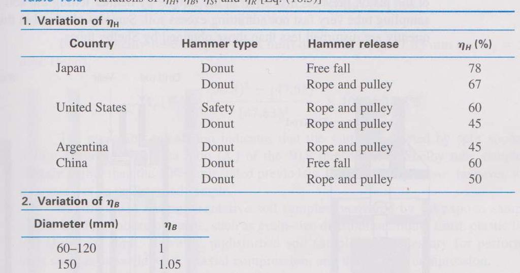
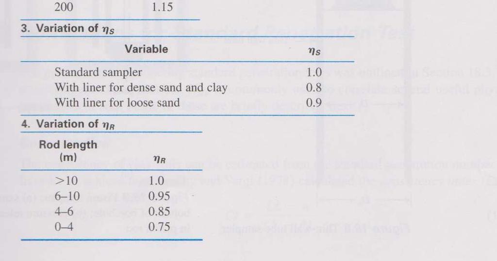
 n B = correction for borehole diameter n S = sampler correction n R = correction for rod")
39 Standard Penetration Test (SPT) N 60 = corrected SPT number N = SPT number n H = hammer efficiency (%) n B = correction for borehole diameter n S = sampler correction n R = correction for rod length
40 Standard Penetration Test (SPT)

41 Standard Penetration Test (SPT) q u = unconfined compression strength P a = atmosphere pressure = 100 kpa N 60 = corrected SPT number
42 Example 5(SPT) A granular soil was subjected to standard penetration test at depths of 3 m. Ground water level occurred at depth of 1.5 m below the surface of the soil which was saturated and had a unit weight of 19.3 kn/m 3. The N count was 15. Determine the corrected value N.
43 Solution (SPT) Effective overburden pressure; = [(3)(19.3)] [(1.5) (10)] = 43 kn/m 2 From the chart, For effective overburden pressure = 43 kn/m 2 N /N = 2.1 Therefore N = (15) (2.1) = 31
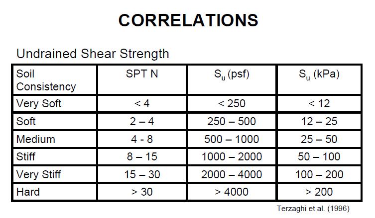
44 CORRELATIONS BETWEEN SPT AND SOIL PROPERTIES Relative Density Effective Stress Friction Angle Undrained Shear Strength
45
46
47
48
49 Vane shear test To determine in shear strength for soft clay soils. A vane tester is made up of two thin metal blades (H = 150 mm with D = 75 mm) attached to a vertical shaft. The test is carried out by pushing the vane tester into the soil (3 x diameter of vane) and then applying a torque, T(12 0 /minute) to the vertical shaft. The clay s cohesion can be computed by using the following formula: T = πc u 2 D H 2 + D 6 3
50 Example 6 (Vane shear test) A vane, used to test a deposit of soft clay, required a torque of 67.5 Nm. The dimensions of the vane were: D = 75 mm, H = 150 mm. Determine a value for the undrained shear strength of the clay.
51 c u = 44 kn/m 2 + = 6 D 2 H D c T 3 2 u π + = x c 67.5 x u 3 π Solution (Vane shear test)
52 Plate bearing test To estimate bearing capacityof soil for spread footing by obtain a load/settlement curve. The test consists of application of a compressive stress to soils by a rigid bearing plate. A trial pit is excavated to the required level and a steel plate is set on the soil at the bottom of the pit. A static load is applied to the plate in successive increments, and the extent and rate of the settlement is recorded. Further increments of load are added and this procedure is repeated until the soil below the plate fails. (Peak load reached or settlement is 10% of plate diameter)

53 Pile loading test Loading tests are usually carried out on one of the piles to be used in the structure installed at an appropriate depth to determine the ultimate load of the pile. Test load is applied in equal increments until all observable settlement has ceased. Curves settlement vs. loadand settlement vs. time are plotted
54 Sand replacement test This test is to determine the soil density at the site. A cylindrical hole approximately of diameter 100 mm and depth 150 mm is dug out and excavated material is then carefully weight. The sand pouring cylinder is placed over the hole and sand run out to fill it, and so determine its volume.
55 Light dynamic cone penetrometer(jkr probe) This testing is widely used in Malaysia to estimate bearing capacityof soil by replacing Mackintosh Probein The probe consists of a cased harden steel pointer of 25 mm diameter and 60 0 cone. The pointer is screwed onto the lower end of the rod. The rods are of 12 mm diameter HY 55C steel, each of length 120 cm. Driving is executed with small hammer of 5 kg in weight and falling through a fixed of 280 mm along a guided rod. The total number of blows required for the pointer to penetrate a distance of 300 mm is recorded. Maximum depth of penetration is about 12 m or 400 blows/300 mm.
56 Light dynamic cone penetrometer(jkr probe)
57 Light dynamic cone penetrometer(jkr probe) The correlation between JKR Probe penetration resistance in number of blows/ft and the allowable bearing capacity is given in figure below.
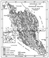
58 Site investigation report The site investigation report is the final product of the exploration programmed. It consists of a summary of the ground conditions encountered, a list of tests carried outand recommendations as to possible foundation arrangements. Reports are generally prepared in sections, headed as described in the following section: Introduction Summary the location of the site, date of investigation, name of the client and the equipment used. Description of site Here a general description of the site, general geology of the area and map showing site location and borehole locations.
59 Site investigation report
60 Site investigation report Description of subsoil conditions encountered This section should consist of short and readable subsoil conditions refer to borehole journal. Borehole journals A borehole journal is a list of all the materials encountered during the boring and best shown as borehole log. Description of laboratory soil tests This simply a list of the test carried out together with a set of laboratory sheets. Recommendations and conclusion In this section, recommendations as to possible foundation types and modes of construction should be given.
61 Site investigation report