Predictive Modeling and Design Solutions for Beneficial Use of Dredged Material
|
|
|
- Liliana McCoy
- 5 years ago
- Views:
Transcription


1 Predictive Modeling and Design Solutions for Beneficial Use of Dredged Material Presented by Tom Wang, P.E., and Kathy Ketteridge, Ph.D., P.E. January 28, 2016
2 Overview of Presentation Introductions Examples and design considerations of beneficial use (BU) opportunities Predictive modeling for BU Dredging, transport, and placement methods for BU Innovative construction materials and methods Case study discussion Questions


3 Integrated Approach is Key to Success Constructability Concerns Goals of BU Project Design for Beneficial Use (BU) Construction Equipment and Methods Predictive Modeling

4 Beneficial Use Design Guidance USACE publications USEPA EM Dredged Material Beneficial Uses DRP and DOER papers and case studies EPA842-B Beneficial Use Planning Manual
5 Beneficial Use (BU) Opportunities
")

6 Beneficial Use Opportunities Confined Aquatic Disposal (CAD) Confined Disposal Facility (CDF) Shoreline Development Shoreline Remediation Cap


7 Beneficial Use Opportunities, continued Beach Nourishment Habitat Restoration - Mitigation
8 Predictive Modeling for BU Projects

9 Physical Stability of Placed Sediment Objective: Evaluate short- and long-term physical stability of placed material due to hydrodynamic forcing Tools: ADCIRC, STWAVE, Delft- 3d, SWAN, M2D and others Data needs Site conditions Design conditions BU sediment characteristics Maximum Predicted Current Field Around BU Island (M2D Model)

10 Physical Stability of Placed Sediment Hydrodynamic Forcing Conditions Tidal currents Estuarine processes Wind-waves Vessel wakes Propeller wash Riverine currents Outfalls/stormwater Simulation of Hurricane Katrina for Port of Gulfport (wind stress)


11 Keyport Lagoon, U.S. Navy Tidal Currents (ADCIRC) and Excess Shear Stress

12 Hancock County Living Shorelines, Mississippi Sound Wave Energy along Shoreline (SWAN)

13 Esquimalt Harbour, British Columbia, Canada Prop Wash Evaluation CFD Code Need to predict specific velocity field behind the prop Evaluate scour potential based on predicted velocity field Example shows velocity field around constructed containment wall

 Transformation of")
14 Sustainability (SLR) Objective: Evaluate impacts to project over design life based on predictions of sea level rise Tools: Hydrodynamic models and GIS spatial modeling tools Data needs Site conditions Design conditions Habitat conditions and characteristics Sea level rise estimates (typically through 2100) Transformation of Tidal Wetlands in DE
15 Geotechnical Modeling Dredged material bulking and settlement (short-term) Foundation consolidation (long-term) PSDDF Model Settlement during construction Long-term consolidation
")
16 Contaminant Mobility (Benthic) Mobility of contaminants through the placed sediments Groundwater pathways Reible Model (1998 EPA Cap Guidance document) AQFATE

17 Contaminant Mobility (Suspended) Objective: Assess water quality impacts resulting from dredging Turbidity Dissolved contaminants Tools: ADDAMS DREDGE and STFATE modules; EPA Plumes Data needs Site conditions Sediment characteristics Dredge characteristics and operations Disposal operations
18 Summary of Predictive Modeling for BU Beneficial Use Options Physical Stability Sustainability Contaminant Mobility (Benthic) Contaminant Mobility (suspended) Geotechnical Considerations Confined Disposal Facility/ Shoreline Development Confined Aquatic Disposal Beach Nourishment Habitat Restoration/Mitigation Sediment Remediation Cap Considered ++ Important +++ Critical for Design
19 Dredging, Transport, and Placement Key considerations in equipment and method selection Intended beneficial use of dredged materials at placement site Distance between dredge and placement sites Dredging vs. placement production rates Substrate suitability of dredged material for beneficial use Sediment contamination Placement site timeframe to achieve functionality Short-term dredge material bulking and settlement Long-term consolidation (sediment and foundation) Dewatering or treatment needs
20 Dredging, Transport, and Placement (cont.) Key considerations in equipment and method selection Predictive modeling results Empirical laboratory or bench-scale testing results Environmental impacts Water quality impacts at dredge and placement sites Habitat impacts Ability to employ construction BMPs to mitigate impacts
21 Dredging, Transport, and Placement (cont.) Beneficial Use Options Confined Disposal Facility/ Shoreline Development Dredging Method (Mech, Hydr) Transport Method (Barge, Pipeline) Clean or Contam. Sediment Active Dewatering Typically Used Treatment Typically Used Both Both Both Yes Sometimes Confined Aquatic Disposal Mechanical Barge Both No No Beach Nourishment Hydraulic Pipeline Clean No No Habitat Restoration/Mitigation Both Both Clean No No Sediment Remediation Cap Mechanical Barge Clean No Sometimes


22 Dredging and Transport Technologies Mechanical Barge transport Unlimited transport distance Low bulking (i.e., near in-situ) Intermittent placement Debris is relatively easy Lower production rate Hydraulic Pipeline transport Restricted transport distance High bulking (i.e., hydraulic slurry) Continuous placement Debris is challenging Higher production rate

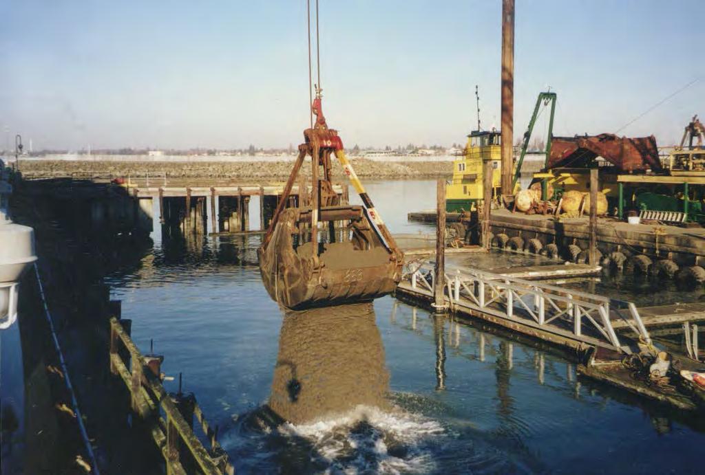
23 Mechanical Dredging Technologies Derrick Dredge (aka Clamshell Dredge)

24 Hydraulic Dredging Technologies Swinging Ladder Cutterhead Dredge

25 Hydraulic Dredging Technologies (cont.) Trailing Suction Hopper Dredge
26 Dredged Material Transport and Screening Transport equipment depends on dredge type and staging/processing needs Barge transport Pipeline transport Staging area availability and size Staging/processing depends on final placement site Debris screening Dewatering Treatment Overland transport

27 Mechanical Dredge Barge Transport

28 Hydraulic Dredge Pipeline Transport

29 Screening Debris


30 Mechanical Placement Barge placement Telebelt placement Barge transport for dredged material Capable of placing wide variety of material Multiple placement methods: barge, rehandling, conveyor, tremie GPS enabled for documentation of area coverage Thin layer placement with rehandling bucket


31 Hydraulic Placement Slurry transport via hydraulic pumps and pipeline Barges equipped with anchoring system and GPS Ideal for sand and finer material up to 1 inch in diameter Thin layer cover combines dredging and precision placement, restores marsh elevation Hydraulic with diffuser screen Hydraulic diffuser Thin layer capping over marsh
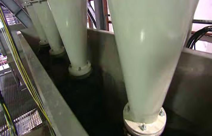
 Hydrocyclone for")
32 Sediment Dewatering Passive dewatering Stockpiles, barge dewatering Wick drains Surcharging Effectiveness varies with material type Less certainty Geotubes (hydraulic dredging) Contained passive dewatering Need space and time Used for beach nourishment, temporary berms, contaminated sediment dewatering Active dewatering Filter or belt press (mechanical or hydraulic dredging) Hydrocyclone for size separation More certainty

33 Empty Geotubes Prior to Filling

34 Full Geotubes Releasing Water

35 Excavating a Full Geotube
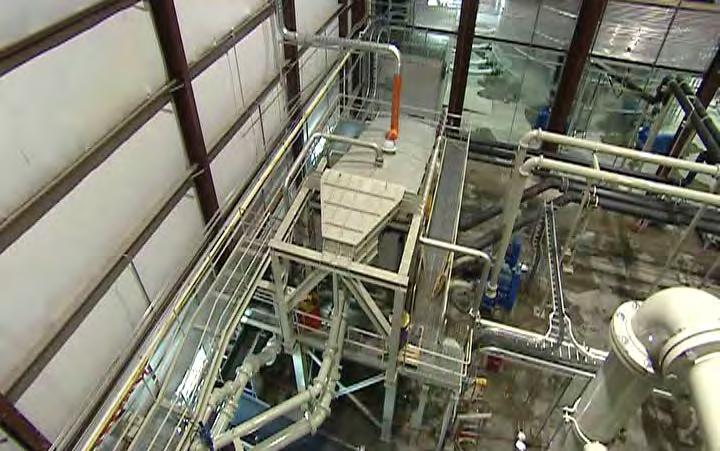
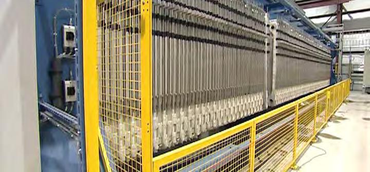
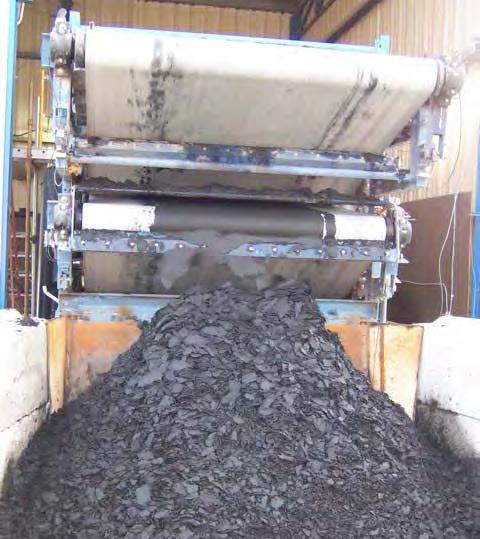
36 Active Dewatering Equipment

37 Hydrocyclone Size Separation
 Slurried dredge material Contaminated fines and")
38 Hydrocyclone Size Separation (cont.) Slurried dredge material Contaminated fines and water Washed sand


39 Treatment Stabilization Adding lime/cement/other to Bind up water Reduce chemical leachability Increase strength Can be simpler than dewatering Typically used to address site stability or strength needs, or sediment contaminants
40 Confined Disposal Facilities
41 CDF Design Guidance U.S. Army Corps of Engineers publications EM Dredging and Dredged Material Disposal EM Confined Disposal of Dredged Material Dredging Research Program (DRP) Dredging Operations and Environmental Research (DOER) EM Slope Stability Source: USACEPublications/EngineerManuals.aspx

42 CDF Design Considerations Containment design Static and seismic stability Contaminant mobility Size and capacity Short-term bulking and settlement Long-term consolidation Ponding area to meet water quality criteria Pumping distance Water content Site final use Habitat Shoreline development Recreation

43 Milwaukee Waterway NCDF and Habitat

44 Milwaukee Waterway NCDF and Habitat
45 Confined Aquatic Disposal
46 Confined Aquatic Sites USACE Publications EM Dredging and Dredged Material Disposal EM Confined Disposal of Dredged Material DRP and DOER Reports USEPA Ocean Disposal Manual CAD designs

47 CAD Design Considerations Submerged or emergent Containment design Static and seismic stability Erosion protection Contaminant mobility Size and capacity Short-term bulking and settlement Long-term consolidation Sustainability Pumping distance Water content Site final use Typically habitat function Navigation and anchoring restrictions

48 Port Hueneme Beneficial Use Place Contaminated Sediment in CAD CAD Place CAD Clean Sediment as Beach Nourishment 48
49 Port Hueneme CAD Cross-section -46 MLLW -56 MLLW -43 MLLW Clean Cap -85 MLLW Contaminated Sediments Note: MLLW = mean lower low water

50 Port Hueneme Barge Placement Port Hueneme, USACE, U.S. Navy

51 Port Hueneme Barge Placement Port Hueneme, USACE, U.S. Navy
52 Beach Nourishment and Habitat Restoration


53 Other Beneficial Uses Beach nourishment Agriculture and products Topsoil Aquaculture Berms Stable and feeder Habitat restoration Land improvement Marsh and intertidal habitat
54 Parallel Geotextile Tubes in Perimeter Dikes

55 Deer Island Marsh Creation Design elements 7- to 8-foot-high dike Easterly wing dike Flash board riser weirs Offset to provide bayou Dredged material from Biloxi Lateral Channel Approximately 40 acres were filled with 365,000 cy of sediment


56 Enhancing Existing Marsh Illustration of conceptual model for marsh recovery after thin-layer disposal
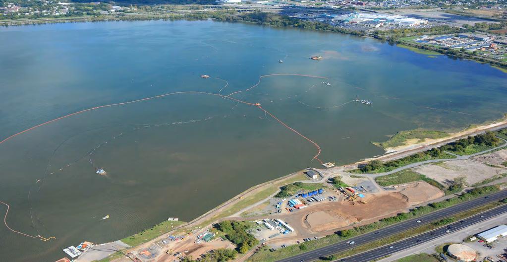
57 Case Study: GP Log Pond

58 GP Log Pond Remediation and Habitat Creation Cost-effective sediment remediation alternative Cap in place >130,000 cy industrial waste product Beneficial reuse of 43,000 cy of dredged material Restoration of 5.6 acres of intertidal and shallow subtidal habitat

59 GP Log Pond

60 Wave Modeling for Cap Stability Whatcom Waterway GP Log Pond
61 Habitat Creation Criteria

62 Key Design Considerations Dredge material as habitat cap Swinomish Channel and Squalicum Harbor combined dredge materials Fine to medium sand + slightly sandy, clayey silt (MH) Coastal stability and sea level rise Shoreline and cap armoring Long-term consolidation Habitat elevations for eelgrass Contaminant mobility Groundwater transport Contaminant isolation Mechanical methods Limit water quality impacts Placement precision
63
64 Questions?