Chesapeake Energy. Shale Operations Overview
|
|
|
- Gabriella Harrison
- 5 years ago
- Views:
Transcription

1 Chesapeake Energy Shale Operations Overview


2 Chesapeake Energy Overview Founded in 1989 Headquartered in Oklahoma City, OK Office regionally located in Canton, OH, Uniontown, OH, Charleston, WV, Jane Lew, WV, Mt. Morris, PA, Canonsburg, PA Exclusive U.S. onshore focus Second-largest producer of U.S. natural gas and a Top 15 producer of U.S. liquids 3Q 11 gas production of ~2.8 bcf/d Liquids production of ~94 mbbls/d 8.3% of daily U.S. natural gas production is from Chesapeake Nation s most active horizontal driller #1 in the world in horizontal shale drilling over past 10 years; > 4,100 wells Exceptional drilling success rate 99% 2

3 Chesapeake Energy Overview Most active driller in U.S operated rigs currently 9 rigs currently drilling in the Utica Shale area ~27 rigs currently drilling in the Marcellus Shale area Consistent production growth 21 st consecutive year of sequential production growth Unparalleled inventory of U.S. onshore leasehold and 3-D seismic 29 million acres of 3D seismic data Lower risk of suboptimal return on capital Higher production rates 3
4 Chesapeake Energy Overview ~ 15 mm net acres of U.S. onshore leasehold 1.35 million acres acquired in Ohio Acreage position in gas shale plays: Barnett Shale 220,000 Haynesville Shale 460,000 Marcellus Shale 1,780,000 Acreage position in unconventional oil plays Anadarko Basin 2,385,000 Eagle Ford Shale 460,000 Permian Basin 835,000 Powder River and DJ Basin 595,000 Advantageous joint venture arrangements and partnerships StatoilHydro, Total, Plains Exploration and Production Company, CNOOC Utica JV partner to be announced soon. 4
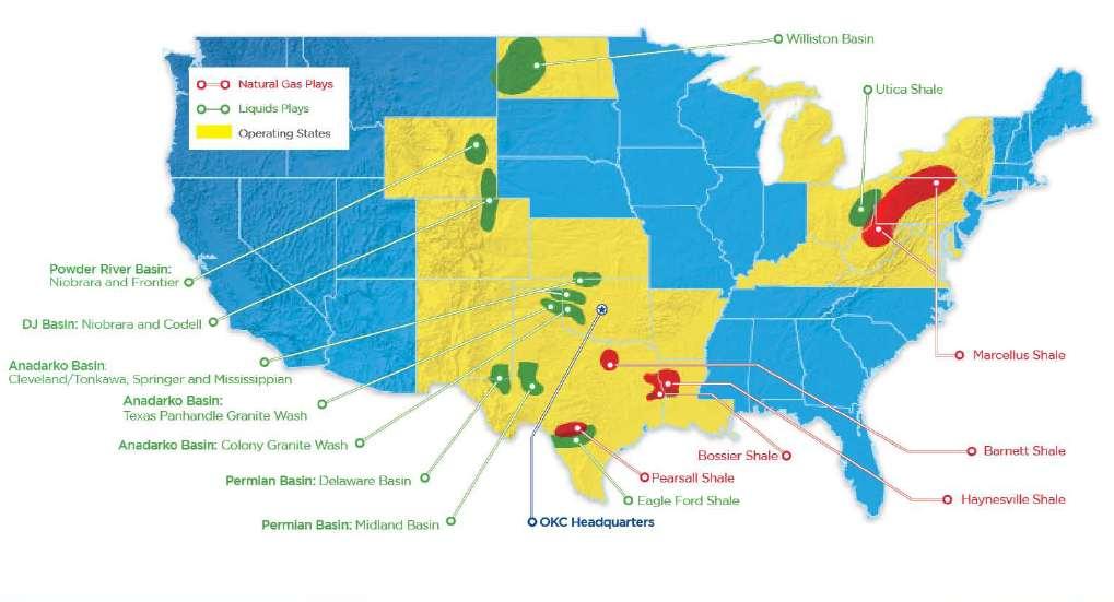
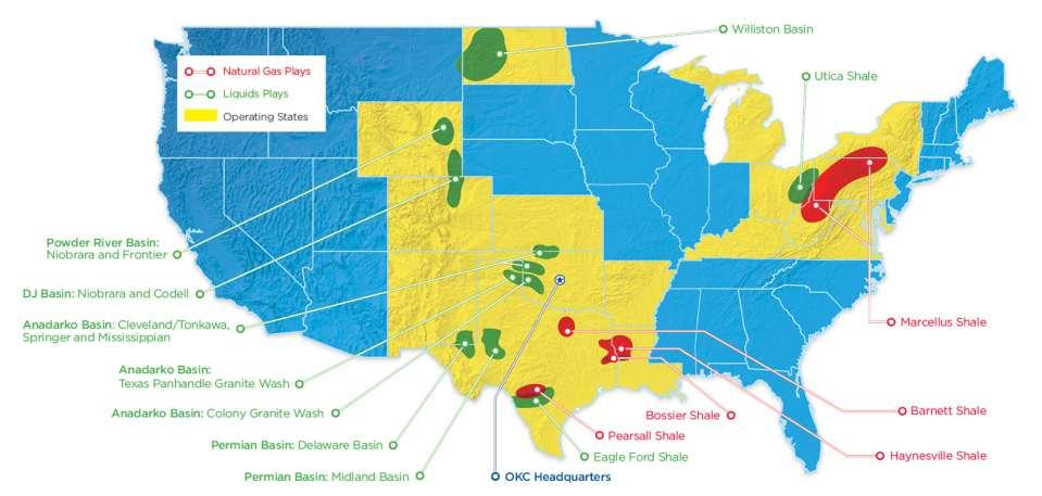
5 Chesapeake s Key Operating Areas 5

6 Characteristics of Shale Formations Found in organic-rich sedimentary rocks (shales) that were originally deposited as muds within tidal flats and deep water basins Shale formations can be found 1 mile or more underground Dense rock with low permeability Typically requires a combination of horizontal drilling and hydraulic fracturing for the natural resources to be recovered in economic quantities 6
 Extensive well log and petrophysical data as well as 4,000 feet of proprietary core")
7 Major Liquids Discovery- CHK s Ohio Utica Shale Began leasing in Ohio for Utica in mid-2010 now have: 1.36 mm net acres of leasehold, by far the largest position in the industry (~50% of the potentially drillable acres) Extensive well log and petrophysical data as well as 4,000 feet of proprietary core samples Spudded 19 horizontal wells to date, 8 being completed Strong initial drilling results from 7 horizontal wells All from the dry and wet phase of the play Early in the process of evaluating the oil phase CHK is currently operating 9 drilling rigs in the play Plan to increase operated rigs in the play up to 8 by YE 11, up to 20 by YE 12 and up to 30 by YE 14 Believe the play is likely most analogous, but economically superior, to the Eagle Ford in South Texas 7
8 The Production Process Five Steps Site selection and well pad preparation Drilling the well Completing the well Marketing the resources Reclaiming the site

9 Site Selection A number of factors are considered in selecting a drilling site: Favorable geology Topography Access Roads Routes for pipelines and utilities Proximity to schools or residential areas Environmental factors such as wetlands and sensitive wildlife habitat Available water source(s)

10 Use of Roads Chesapeake Energy prefers to use a Road Use Maintenance Agreement (RUMA) for dealing with potential effects on public roads Has been used extensively for Chesapeake s operations are in PA Currently utilizing 50+ miles of county/township roadways in Ohio as haul routes To date in 2011, Chesapeake has spent ~$25 million in county/township roadway upgrades or repair projects Currently employing 2 primary roadway engineering and construction firms to facilitate route planning, design and construction 10
11 Haul Route Planning Prior to any construction activities Field visit to determine preliminary haul route Construct preliminary inspection report Pavement condition, bridge structures, culverts, turning radius, etc. Authorize and coordinate engineering investigation work Geotech, bridge, culvert, etc. Coordinate survey work (ROW, topo, loco, etc.) Meeting with roadway authorities Discuss road agreements, upgrades needed, construction schedule Coordinate RUMA approval process 11
12 Haul Route Design/Construction Design Site survey to identify drainage issues, drive locations, base repair areas Base map creation Preliminary plan design Circulate to Chesapeake, roadway authority and utility companies for review Final Plan design Coordinate roadway authority plan approval Prepare engineer s construction cost estimate Prepare out-to-bid package Construction Solicit bids and award projects Coordinate construction inspection, testing and survey work Manage contractors Project close-out (punch list, roadway authority approval) 12
13 Pre-drill Testing Chesapeake Energy conducts pre-drill testing on water sources prior to conducting drilling operations in an area Testing is done on water sources within 3,000 feet from the vertical portion of the well Includes springs, wells, streams and ponds The testing establishes a baseline of water quality conditions for both Chesapeake and the property owner The testing is free for the property owner A representative from Chesapeake will collect a water sample It is preferred that the property owner be present during the collection Analysis is conducted by a state-certified analytical laboratory The property owner receives a copy of the laboratory s analysis 13

14 Well Pad Preparation Well pads can be located in rural or urban areas Pad preparation requires approximately 4-6 weeks Typical horizontal well pad requires 3-5 acres to construct Approximately 5,000 tons of aggregate is used for construction Appropriate erosion and sediment controls are installed 14
15 15
16 16

17 Drilling the Well Using Today s New Technology Wells are drilled and constructed to recover the natural resources while protecting the environment and providing for the safety of workers and area residents Drilling is a 24/7 operation Reduces rig time on location The drilling phase is a temporary operation, typically lasting 4 weeks per wellbore Multiple wells may be drilled in succession Chesapeake Energy utilizes a closed-loop drilling system All drilling materials are contained No materials collected in earthen pits 17

18 Drilling the Well Using Today s New Technology 18

19 Drilling Best Management Practices Pre-job meetings Review safety, operational and environmental concerns Equipment staging Staged to allow for visual inspection of potential leak points Staged to take advantage of site construction measures Closed-loop drilling system Solids/cuttings will be separated from the drilling fluid and maintained in steel tanks Tanks hauled off and disposed of consistent with OEPA regulations Fluids diverted back to mud tanks for reuse Use of air drilling through freshwater aquifers 19
20 Drilling Best Management Practices Chemical containers, tanks and process vessels Containers greater than 55-gallons placed inside lined secondary containment Secondary containment may include temporary earthen berms with polyethylene underlining the entire contained area Or, a portable containment area constructed of steel, PVC or other suitable material Hoses and fittings Where practical, hoses will be run within secondary containment Drip-pots or troughs placed under all hose connections in concentrated chemical transfer service outside of secondary containments 20

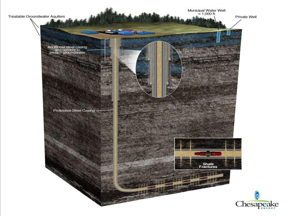
21 How Deep? 21

22 Drilling the Well- Groundwater Protection 4 or more layers of protection are installed in the well to isolate the well from the surrounding strata and protect groundwater supplies and the environment Multiple layers of steel casing and cement are utilized Casing set in place below freshwater aquifer zone FIT test performed and cement logs recorded to ensure proper seal ODNR must be notified prior to the installation and cementing of all casing strings 22

23 Drilling the Well- Groundwater Protection 23
 and pumped into the shale reservoir under pressure 99.")
24 Well Completion-Hydraulic Fracturing After the drilling rig is removed, hydraulic fracturing ( fracing ) begins Not new technology; has been in use since after World War II ODNR estimates over 80,000 wells have been hydraulically fractured in Ohio Water is mixed with proppant (such as sand) and pumped into the shale reservoir under pressure 99.5% of fracturing fluid is made up of water and sand ~6 million gallons of water needed per well Generally takes 7-10 days per wellbore For more information on hydraulic fracturing, please visit AskChesapeake.com 24
25 25

26 Hydraulic Fracturing Site Layout 26

27 Well Completion Best Management Practices Containment Chemical trailers, containers and raw chemical transfer equipment will be placed in secondary containment Troughs and/or drip pots will be placed underneath hose connections in concentrated chemical service not located within secondary containment Use of freshwater impoundments only Aqua Renew Program 27


28 Typical Deep Shale Gas Fracturing Mixture Water and Sand: 99.5% Other: 0.5% Acid Friction Reducer Surfactant Gelling Agent Scale Inhibitor ph Adjusting Agent Breaker Crosslinker Iron Control Corrosion Inhibitor Antibacterial Agent Clay Stabilizer 28

29 Fracturing Fluid Additives 29
30 Process Currently recycling / reusing nearly 100% of produced water Produced water is collected and stored in holding tanks onsite Then pumped from the tanks through 20 micron filter Then pumped into a clean storage tank Prior to reuse, the water is tested for chlorides and then blended accordingly with freshwater during the next fracturing job Benefits Reduces or eliminates need for water to be sent offsite for disposal Reduces impact on local supplies Reduces truck traffic, lower impact on roads, noise and air Reduces the cost of operations 30

31 Marketing / Reclaiming the Site Production equipment is installed Pipeline carries natural gas to market Depending upon production level, liquid production may be trucked or transported via pipelin Produced water is retained on location in tanks until removed via truck Site is reclaimed and landscaped Site is reduced to approximately 1 acre Small access road will be retained Company returns regularly Maintain equipment / monitor production rate 31

32 Who Shares In The Revenue Mineral Owners Bonuses and royalties Local workers Wages and benefits Local Business Subcontractors and service companies Counties, Cities, School Districts Ad valorem and other taxes Other Stakeholders Charitable organizations Chesapeake shareholders

33 Questions? For more information: AskChesapeake.com Information provided is subject to change based on multiple factors