Technical Strategic Plan for Decommissioning of the Fukushima Daiichi. Nuclear Power Station of. Tokyo Electric Power Company Holdings, Inc.
|
|
|
- Shon Johns
- 5 years ago
- Views:
Transcription
1 Technical Strategic Plan 2017 for Decommissioning of the Fukushima Daiichi Nuclear Power Station of Tokyo Electric Power Company Holdings, Inc. August 31, 2017 Nuclear Damage Compensation and Decommissioning Facilitation Corporation
2
3 All rights reserved except for reference data. No part of this document may be reproduced, edited, adapted, transmitted, sold, published, digitalized or used in any other way that violates the Copyright Act for any purpose whatsoever without the prior written permission of Nuclear Damage Compensation and Decommissioning Facilitation Corporation.
4 Table of Contents 1. Introduction Strategic Plan Purpose of the Strategic Plan Basic concept of the Strategic Plan Fundamental policy Five guiding principles Positioning of Strategic Plan 2017 and its overall structure Strategy for reducing risks posed by radioactive materials Progress in Decommissioning of Fukushima Daiichi Nuclear Power Station Basic thought in reducing risk of radioactive materials Risk source identification Risk estimation Hazard Potential Safety Management Risk evaluation Current status of risk reduction measures Category I risk reduction measures Category II risk reduction measures Category III risk reduction measures Challenges during risk reduction Implementing risk reduction strategies Strategic Plan for fuel debris retrieval Study plan for fuel debris retrieval (risk reduction) Positioning of a strategic proposal towards determining a fuel debris retrieval policy Flow of studies on a strategic proposal towards determining a fuel debris retrieval policy Basic concept for ensuring safety in the fuel debris retrieval operation Current states of each unit Maintenance and management of a stable state at each unit Understanding and estimating reactor conditions for each unit Conditions of reactor buildings Understanding the condition in the PCV by actual investigation Effects of risk reduction by fuel debris retrieval Potential risk of fuel debris Risk level of fuel debris Discussions on reduction of risk of fuel debris Feasibility of fuel debris retrieval method
5 4.5.1 Characteristics of fuel debris retrieval methods Technical requirements for the fuel debris retrieval methods Ensuring containment functions Maintaining cooling functions Criticality control Ensuring the structural Integrity (aseismicity) of thepcv and reactor building Reducing occupational radiation exposure during on-site works Ensuring occupational safety Establishment of access routes to fuel debris Development of the fuel debris retrieval equipment and devices Establishment of system equipment and working areas Technical requirements for storage of fuel debris in safe and stable condition Fuel debris handling (collecting, transferring and storing) Handling of waste generated during fuel debris retrieval work Safeguards Evaluation of feasibility of the methods Technical requirements for ensuring safety while retrieving fuel debris Technical requirements for method Evaluation summary of method feasibility Comprehensive evaluation based on Five Guiding Principles Evaluation Method Evaluation result Proposal for deciding fuel debris retrieval policies and efforts after decision (strategic proposal) Proposal for deciding fuel debris retrieval policies Efforts after deciding fuel debris retrieval policies Strategic Plan for waste management Study policy on the Strategic Plan for waste management International safety principles on radioactive waste management Basic principles for ensuring the safety of radioactive waste Principles for ensuring the safety concerning predisposal management of radioactive waste Principles for ensuring the safety of radioactive waste disposal Current Status of Solid Waste Management Storage Waste characterization Processing and disposal
6 5.4 Proposal for compilation of the basic concept of solid waste management (strategic proposal) Characteristics of solid waste Solid waste management policies Pesent efforts and R&D based on solid waste management policies R&D initiatives Basic policy for R&D Basic policy Entire perspective of R&D Promotion of R&D aimed at utilization for the decommissioning process R&D activities performed by TEPCO Project of decommissioning and contaminated water management Reinforcing cooperation in R&D R&D priority agenda based on needs and its strategic promotion Building R&D Infrastructure Based on Mid-and-Long Term vision Developing and securing human resource Enhancement of international cooperation Integrating and utilizing wisdom Active information dissemination to international communities Close cooperation between relevant organizations Future actions Enhancing project management capabilities Engagement with stakeholders Consideration for project sustainability
7 <Appendix> Appendix 1: Japanese Government's Organizational Framework for Decommissioning the Fukushima Daiichi NPS... A-1 Appendix 2: Information on the Strategic Plan... A-2 Appendix 3: Overview of SED indicator... A-5 Appendix 4.1: Periodic measurement of plant data... A-8 Appendix 4.2: Results of PCV internal survey... A-16 Appendix 4.3: Survey results of S/C and torus room... A-23 Appendix 4.4: Results of muon detection... A-25 Appendix 4.5: BSAF project outline and results so far... A-28 Appendix 4.6: Characteristics of MAAP code and SAMPSON code and analysis results... A-30 Appendix 4.7: Summary of heat balance method and estimation result... A-32 Appendix 4.8: Location of fuel debris estimated from plant parameter trend... A-36 Appendix 4.9: List of properties of fuel debris... A-40 Appendix 4.10: Status of the comprehensive analysis and evaluation of the conditions inside the reactor in each unit... A-43 Appendix 4.11: Studies on containment function... A-45 Appendix 4.12: Study of water level at the bottom of PCV when retrieving fuel debris... A-49 Appendix 4.13: Preliminary Seismic Margin Evaluation of RPV and PCV.... A-52 Appendix 4.14: Development of fuel debris retrieval equipment and devices... A-60 Appendix 4.15: Risks accompanied by fuel debris retrieval tasks... A-71 Appendix 5: Status of Solid Wastes Management, and Their Storage Management Plan... A-74 Appendix 6.1: Interim Report by Research Partnership Task Force... A-76 Appendix 6.2: Changes in elective subjects of secondary examination for professional engineers (category of atomic energy and radiation)... A-81 Appendix 7: Conditions at TMI-2 and Chernobyl Unit 4... A-82
8 Abbreviations and short forms AC CAMS CEA CRD CS CST D/W DHC DOE DSP FDW FP GPUN IAEA ICRP IRID JAEA MCCI NDA NDF NDF Act Revised NDF Act NRC NSC OECD/NEA PCV RPV S/C SED TMI-2 Implementation plan Underwater ROV Strategic plan Matters to be addressed Mid- and Long-term Roadmap TEPCO Fukushima Daiichi NPS Abbreviations and short forms Definitions and Officinal Names Atmospheric control system Containment Atmospheric Monitoring System Commissariat à l énergie atomique et aux énergies alternatives (France) Control rod drive mechanism Core spray system Condensate storage tank Drywell Drywell humidity control system United States Department of Energy Dryer separator pool Feed water system Fission products General Public Utilities Nuclear Corporation (owner of TMI-2) International Atomic Energy Agency International Commission on Radiological Protection International Research Institute for Nuclear Decommissioning Japan Atomic Energy Agency Molten core concrete interaction Nuclear Decommissioning Authority (United Kingdom) Nuclear Damage Compensation and Decommissioning Facilitation Corporation Nuclear Damage Compensation Facilitation Corporation Act A law that partially revises the Nuclear Damage Compensation Facilitation Corporation Act Nuclear Regulatory Commission (United States) New Safe Confinement, arched-shaped, built to cover the remains of the No. 4 unit at the Chernobyl Nuclear Power Plant Nuclear Energy Agency, Organization for Economic Co-operation and Development Primary containment vessel Reactor pressure vessel Suppression chamber Safety and Environmental Detriment, the method developed by the NDA to express risk levels Three Mile Island Nuclear Power Plant Unit 2, United States Implementation Plan of the Measures for the Specified Reactor Facilities at Fukushima Daiichi Nuclear Power Station Underwater remotely operated vehicle Technical Strategic Plan 2017 for the Decommissioning of the Fukushima Daiichi Nuclear Power Station of Tokyo Electric Power Company Holdings, Inc. Matters which are requested to be taken by Tokyo Electric Power Company, Inc. when the Fukushima Daiichi NPS was designated as Specified Nuclear Facility Mid- and Long-term Roadmap towards the Decommissioning of TEPCO s Fukushima Daiichi Nuclear Power Station Units 1 4 Tokyo Electric Power Company Holdings, Inc. Fukushima Daiichi Nuclear Power Station of Tokyo Electric Power Company Holdings, Inc.
9 Term CRD housing MAAP SAMPSON Reactor well shield plug Submersion method Partial submersion method Clearance Grating Actual debris Heavy nuclide Defense in depth Sludge Slurry Fuel debris Pedestal Muon-based fueldebris detection technology Simulated debris Mock-up Preparatory engineering Loose debris Robustness Nomenclature Description Housing that stores the control rod drive mechanism The severe accident simulation code improved and controlled by the U.S. Electric Power Research Institute (short for Modular Accident Analysis Program) The simulation code improved and controlled by the Institute of Applied Energy, consisting of the models and modules formulated based on the multi-dimensional equations and theoretical formulae that precisely express physical phenomena (short for Severe Accident analysis code with Mechanistic, Parallelized Simulations Oriented toward Nuclear Fields) A concrete lid on top of PCV installed for radiation shielding (a part of the floor of the uppermost floor of the R/B during operation) A retrieval method by filling to the top of the PCV with water to submerge the fuel debris The debris retrieval method that does not fill the PCV fully with water. Fuel debris is partially exposed to the air when removed. Clearance system refers to a system under which the government confirms that the concentration of radioisotopes of materials used in a nuclear facility is below the "Clearance Levels" (the level at which the impact is negligible to human health). The materials confirmed by the government are removed from the regulations on nuclear reactors, and will be subject to regulations under laws on wastes and recycle as conventional industrial wastes or valuables Steel grating footings, used as side-ditch coverings and scaffolds. Actual fuel debris retrieved from the reactor vessels as opposed to simulated debris Actinide nuclides such as uranium and plutonium To protect humans from safety threats, several barriers (levels of protection) are provided, each having a specific aim. If protection has failed on a given level, the barrier of the next level provides protection. This system is a preparation for uncertainty, and the concept of this system is essential to ensure nuclear safety. Muddy material including radioactive material Liquid-state material in which minerals and sludge are mixed Nuclear fuels molten and mixed with parts of reactor internals due to loss of reactor coolant and resulted in a re-solidified state The cylindrical base that supports the reactor body. Its inside is filled with concrete. Technology that determines the positions and forms of fuel, using the characteristics of muonic atoms (muons) that arrive from the cosmos and atmospheric air. The number of muons and their trajectories change depending on the density of the material through which they pass through. Artificial objects manufactured by estimating the chemical composition and forms based on the examples of TMI-2 accident Model created to be almost the same as the real object Engineering work conducted to preliminarily determine the feasibility of the planned construction work prior to the basic design conducted at the beginning of ordinary construction Small-size debris found in the TMI-2 molten pool, including fractured pellets, control rods, and resolidified fuel debris The capability to maintain the robust function even when the condition is changed to a certain extent from what is expected
10 1. Introduction The overall approach to the decommissioning of the Fukushima Daiichi Nuclear Power Station of Tokyo Electric Power Company Holdings, Inc. (Fukushima Daiichi NPS) started based on the Midand Long-Term Roadmap towards the Decommissioning of TEPCO s Fukushima Daiichi Nuclear Power Station Units 1 4 (Mid- and Long-Term Roadmap), released by the Japanese Government in December The handling of urgent issues, such as contaminated-water management and fuel removal from spent-fuel pools, has been placed on top priority; however, to fully complete reactor decommissioning, long-term measures are required such as fuel-debris retrieval, and it is essential to prepare a mid- and long-term decommissioning strategy. On August 18, 2014, the former Nuclear Damage Compensation Facilitation Corporation was reorganized into the Nuclear Damage Compensation and Decommissioning Facilitation Corporation (NDF) as an organization responsible for technical studies to proceed with reactor decommissioning properly and steadily from a mid- and long-term perspective. Based on the Nuclear Damage Compensation Facilitation Corporation Act (NDF Act), the NDF has been developing the Technical Strategic Plan for the Decommissioning of the Fukushima Daiichi Nuclear Power Station of Tokyo Electric Power Company (Strategic Plan) annually since 2015, as part of its statutory obligations: the provision of advice, guidance and recommendations for ensuring an appropriate and steady performance of the decommissioning, and the research and development of decommissioning technologies. For this year in particular, the Mid- and Long-Term Roadmap (revised June 2015) requires that decisions be made on fuel debris retrieval policies for each unit, and that the basic concept of solid waste management be compiled. Based on discussions with relevant parties, NDF will be presenting strategic proposals regarding these two matters in the strategic plan. Six years has passed since the Fukushima Daiichi NPS accident, and short-term planning has become possible to a certain extent: on the accident site, contaminated-water management made progress thanks primarily to the land-side impermeable wall, fuel removal from spent-fuel pools also moved ahead, and the outdoor work environment has improved. For the mid- and long-term, although fuel-debris retrieval, reactor interior investigation and R&D have made progress, it is becoming known that the work environment inside the buildings is severe, suggesting the difficulty of the work there in the future. While the decommissioning project is shifting to the phase where mid- and long-term issues should be addressed specifically, the partially revised Nuclear Damage Compensation Facilitation Corporation Act (Revised NDF Act) which was established in May 2017 to implement measures such as obligating TEPCO, the operator, to reserve funds at NDF that are required for decommissioning in order to execute decommissioning in a more reliable manner. With this Act in effect, the duties of NDF now include operations for the management of these decommissioningfund reserves: (1) TEPCO will reserve an amount of funds in each fiscal year as determined by the NDF and approved by the competent minister; and (2) TEPCO will proceed with decommissioning while withdrawing the reserved funds based on the withdrawal plan prepared jointly by the NDF and TEPCO and approved by the competent minister ( withdrawal plan ). Additionally, as stated in the Revised Comprehensive Special Business Plan (The Third Plan) published in the same month, the decommissioning of the Fukushima Daiichi NPS is a fundamental precondition of the recovery of Fukushima, and is expected to be carried out correctly and steadily. Under this new system, the NDF, the major supervisor and administrator of the decommissioning by TEPCO, is expected to play a greater role and assume greater responsibilities than before, primarily in terms of project management: It will assume such additional duties as (1) the appropriate management of funds for decommissioning, (2) the supervision of an appropriate system for executing the decommissioning, and (3) steady work management based on the 1-1
11 decommissioning reserve fund system. Specifically, through the process of preparing the withdrawal schedule jointly with TEPCO, NDF will provide support for enabling the correct and steady execution of decommissioning, such as conducting assessments of the validity of actions taken by TEPCO from the perspective of project execution and proposing tasks, among other matters, that should be included in the withdrawal schedule. Under these circumstances, the roles shared among the organizations associated with the Fukushima Daiichi NPS decommissioning, which are the Japanese government, NDF, TEPCO, the International Research Institute for Nuclear Decommissioning (IRID) that specializes in research and development, and Japan Atomic Energy Agency (JAEA), are shown in Figure 1-1. The government is creating a Mid- and Long-Term Roadmap that defines the directions for decommissioning and contaminated water countermeasures, and conducts progress management for the various countermeasures based on these. Additionally, the government also provides support for R&D areas that pose high levels of technical difficulties and require government leadership. Based on critical issues and other matters indicated in the Mid- and Long-Term Roadmap, NDF will prepare a strategic plan for aiding in the reliable execution of the roadmap and in reviews considering revisions to the roadmap. With regards to TEPCO, NDF will provide advice and instructions from a technical standpoint to ensure the steady advancement of the decommissioning process. Moving forward, it will manage and monitor the execution of decommissioning based on the decommissioning reserve fund program. Additionally, it is engaged in planning and progress management for R&D by working closely with R&D organizations and sharing with them the status of progress and issues in order to proceed with R&D smoothly. TEPCO bears the responsibilities of the operator in the decommissioning of the Fukushima Daiichi NPS. As such, it is conducting engineering operations including designs and work planning, has submitted the Implementation Plan of the Measures for the Specified Reactor Facilities at Fukushima Daiichi Nuclear Power Station (Implementation plan) to the Nuclear Regulation Authority, and is proceeding with approved decommissioning actions. Specifically, it will gear up actions regarding fuel debris retrieval in addition to implementing actions including the retrieval of fuel from spent fuel pools and countermeasures for contaminated water. R&D organizations are engaged in R&D efforts based on the Mid- and Long-Term Roadmap, bringing together knowledge from around the world to efficiently and effectively carry out R&D that will be needed for decommissioning. For the system of the government, refer to Appendix


12 Figure 1-1 Roles Shared by the Organizations Associated with the Fukushima Daiichi NPS Decommissioning 1-3
13 2. Strategic Plan 2.1 Purpose of the Strategic Plan The aim of the Strategic Plan is to contribute to the correct and steady implementation of the Midand Long-Term Roadmap, and to evaluations for revisions to the Roadmap, as well as to provide reliable technological grounds to the Roadmap in order to execute the decommissioning of the Fukushima Daiichi NPS correctly and steadily. The Strategic Plan is prepared based on discussions at Expert Committees, whose aim is to acquire opinions regarding specific issues from experts having specialized knowledge and from the representatives of organizations concerned, and discussions at the Decommissioning Strategy Board, which is a function of review by experts of various fields. In addition, international experts are invited to the Decommissioning Strategy Board as International Special Advisors, and various technical gatherings are held, to acquire experience and knowledge concerning decommissioning. 2.2 Basic concept of the Strategic Plan Fundamental policy The Fukushima Daiichi NPS, which has been designated a Specified Nuclear Power Facility, is currently maintained and administered to a given level of stability, and safety measures are being taken as specified by the Nuclear Regulation Authority (NRA), according to the matters for which measures should be taken ( Matters to be Addressed ). However, unlike normal nuclear power plants, the status of the station is not sufficiently grasped, because of the damages of the buildings, fuel debris, spent fuels, generation of contaminated water including radioactive materials, and various radioactive wastes. To proceed with decommissioning in the future, the possibility is undeniable that the risks attributable to radioactive materials become apparent. If no action is conducted and the current conditions are left as they are, the conditions where the risks of radioactive materials exist will continue. The decay of radioactivity will gradually decrease the risks, while the risks may increase in reverse due to the aging deterioration of facilities and other factors. The risks may not always simply decrease with time. Accordingly, the fundamental policy for decommissioning of the Fukushima Daiichi NPS is "to continuously and promptly reduce the risks associated with the radioactive materials generated by the accidents" Five guiding principles (1)Basic attitude towards completing the decommissioning The decommissioning of Fukushima Daiichi NPS is a project in which considerable uncertainty inheres. As a result of the accident, the reactor interior and surroundings are in a radioactive environment and workers are unable to have access there easily. Accordingly, the properties of radioactive materials and the damages of on-site equipment and structures left there remain unknown, posing uncertainty. It is desirable if all the information that is currently difficult to confirm could be collected to eliminate such uncertainty before starting decommissioning; however, many resources, especially a considerably long time, are required to do so. 2-1
14 To realize prompt decommissioning, it is necessary to assume the attitude of taking flexible and prompt approach, based on the directions determined with previously obtained experience and knowledge and with experiment- and analysis-based simulation, placing safety at the top priority, even though a certain extent of uncertainty remains. To proceed with decommissioning flexibly and promptly, the attitude of optimizing the entire project from the long-term, comprehensive viewpoint, and the attitude of making preparations for unexpected cases, are also important. (2)Five guiding principles Based on the basic attitudes, this section presents the Five Guiding Principles of risk reduction to promote the fundamental policy of the Fukushima Daiichi NPS decommissioning. Principle 1: Safe - Reduction of the risks posed by radioactive materials to ensure labor safety Principle 2: Proven - Highly reliable and flexible technologies Principle 3: Efficient - Effective utilization of resources (e.g., human, physical, financial and space) Principle 4: Timely - Awareness of time axis Principle 5: Field-oriented - Thorough application of the three actuals (the actual field, the actual things and the actual situation) A. Principle 1: Safe - Reduction of the risks* 1 posed by radioactive materials to ensure labor safety *1) Environmental impacts and workers exposure In proceeding with the decommissioning of the Fukushima Daiich NPS, it is needless to say that safety is the first priority. The International Atomic Energy Agency (IAEA), like other organizations, specifies the safety principle as protecting humans and environments against risks from radioactive materials. Since safety standards for operational NPSs cannot be applied to damaged reactors, decommissioning should proceed by ensuring safety in accordance with site conditions. Accordingly, the viewpoint of giving priority to the risks that need to be reduced is necessary, that is, risks must be reduced expeditiously to achieve a safe and stable condition, based on the awareness that damaged reactors pose high risks. The attitude of proceeding with the decommissioning while ensuring safety effectively is important, with an awareness of total risk *2 reduction with time. With regard to works such as fuel debris retrieval, for which we have no experience, it will be important to specifically develop concept for ensuring safety for damaged-reactor decommissioning and to start discussion with the NRA in an early stage, with reference to the precedent case at Three Mile Island Nuclear Power Plant Unit 2, United States ( TMI-2 ), where the operator, regulatory authorities and other parties concerned committed themselves as a single team to deal with the accident. To reduce environmental impact, such as public exposure to radiation and environmental contamination risks, it is critical to improve the conditions of controlling the radioactive substances that exist in various forms in the premises. And while steps have been taken to improve working environments to reduce worker exposure to radiation, safety measures, including work-hour management, shield placement, and wearing of protective equipment, 2-2
15 must be taken comprehensively with regards to work that is performed in highly radioactive environments, such as in reactor buildings. Furthermore, sufficient attention should be paid to labor safety as well, to prevent accidents and injuries, because personnel will need to work in the places that are narrow and not easily accessible. *2) Total risk in consideration of the continuation and change of existing risks over time as well as the trade-off between the temporary risk changes due to work performed to reduce risks and resulting risk reduction B. Principle 2: Proven - Highly reliable and flexible technologies The decommissioning of the Fukushima Daiichi NPS is an unprecedented project, which is technically highly difficult and involves many newly developed technologies, because it needs to be carried out under highly radioactive conditions. For the measures to be accomplished in a relatively short period of time, new technology developments should be limited to as few as possible, to minimize the risk of failing development and make progress steadily. In this regard, feasible Japanese and international technologies, namely, technologies and intelligences with high technology readiness levels (TRL), should be adopted and applied where possible. They should be provided with necessary improvements, such as systematization, to suit the site conditions of the Fukushima Daiichi NPS, and their operation needs to be verified and demonstrated in advance to confirm workability under the severe site conditions. Considering a high degree of uncertainty in the site conditions, robust technologies should be selected to enable flexible response to unexpected situations or changes in the situation. Onsite work should be carried out step by step and the course of actions should be adjusted where necessary. In case that selected technologies do not work, it is important to prepare counterplans in advance, such as alternative measures. On the other hand, as decommissioning work proceeds, the development of an entirely new technology may be critical in some cases. For the mid- and long-term issues that require such a technical development, research and development, including fundamentals and baseline studies, should be conducted with matters concerned specified, including needs, objectives, the roles of organizations concerned (e.g., universities, public research institutions and private organizations). Especially the contribution of remote-control technology is highly expected, for use under the environments where radioactivity is unlikely to turn for the better because of difficulty in decontamination. C. Principle 3: Efficient - Effective utilization of resources (e.g., human, physical, financial and space) The decommissioning of the Fukushima Daiichi NPS involves a large amount of complicated tasks and developments over a long period of time. Therefore, resources, including human, physical, financial and spatial ones, may function as a restraint. Their reasonable and effective use will be a key factor for successful decommissioning. As for human resources, who will need to work in a highly radioactive environment, it is necessary to plan and manage the total exposure doses of every construction worker during the construction in order to ensure sufficient personnel supply over a long period of time. In 2-3
16 addition, because the project involves many technical studies concerning R&D and on-site construction, impracticable and unnecessary work should be avoided, aiming to streamlined work. It is also important to secure the human resources necessary for successful decommissioning such as researchers, engineers and workers, and to be committed to human-resource development and technology inheritance. As for physical resources, any facilities and goods brought into the Fukushima Daiichi NPS are highly likely to be treated as radioactive wastes. It is reasonable to use facilities and goods efficiently to minimize the generation of wastes, by avoiding bringing in unnecessary goods, by making the best use of the goods that have been brought in, and by keeping the 3R rule (reduce, reuse and recycle) in mind. As for financial resources, since a large amount of tasks and developments are involved over a long period of time, keeping overall cost reduction in mind is important, in addition to evaluating the cost benefit performance of individual tasks, which is associated with the effective use of human resources, and the investment benefit performance of technological developments and devices. As for spatial resources, although the premises of the Fukushima Daiichi NPS are relatively large compared to those of other nuclear power stations in Japan, it is important that we take into account the possibility that additional facilities may encroach on working spaces, and make effective and efficient use of space including the development and securing of transport routes for equipment and other items. To efficiently use the resources (human, physical, financial and spatial), it is important to evaluate individual tasks and developments, but it is also important to prioritize the measures from the viewpoint of overall optimization from the long-term perspective, in consideration of impact on subsequent tasks. D. Principle 4: Timely - Awareness of time axis Because spending an unnecessarily long period of time on the Fukushima Daiichi NPS decommissioning entails a continuation of risk conditions caused by radioactive materials, it is important to be aware of promptly reducing the risks. Timeliness and the Principle of Proven may be in a trade-off relationship, but it would be preposterous if decisions are postponed and the risk situations are left as they are. It is necessary to proceed with the work carefully in consideration of the risks, while making optimal decisions whenever appropriate. In order to be aware of timeliness, it is important to set a certain target time for each of the actions to be taken as soon as practicable, actions that require steady implementation and actions to be carried out over a long time. In addition, multilayered preventive measures against project risks are also important to avoid time losses and rework. When preventive measures are planned, it is important as well to decide on what risks to address, to what degree to take preventive measures, and to what degree to multilayer the measures. Clarifying the details and levels of safety assessment in advance is also important to prevent time losses and rework. Meanwhile, issues such as waste management and station site closure involve unprecedented situations that are created by a damaged nuclear power station and waste materials produced from the accident. As such, new regulatory systems and standards may be required for these 2-4
17 issues. Dealing with these issues may take a correspondingly long period of time, and should be examined with lead time in mind. E. Principle 5: Field-oriented - Thorough application of the three actuals (the actual field, the actual things and the actual situation) The decommissioning of the Fukushima Daiichi NPS is risk reduction activities associated with radioactive materials on site; therefore, it is important to carry out the tasks in accordance with the Three Actuals concept thoroughly and in a site-oriented manner. The Three Actuals means to understand the precise needs based on the actual site conditions, actual facilities, and what is actually happening at the site, and to choose technologies focusing on on-site applicability. Especially there are risks that the understanding of a technology is different between those who developed it and those who actually apply the achievement on site, or that the understanding by the design sector or management sector and that by on-site workers have gaps. Special attention needs to be paid to these risks and both sides should be encouraged to have common understanding. The on-site applicability is to assess whether a technology under feasibility study (FS) is actually applicable in the site conditions and environment of the Fukushima Daiichi NPS. The assessment of on-site applicability should be judged based on the following factors: Environmental resistance (e.g., radiation, temperature, humidity and light intensity) Accessibility and transportability (e.g., narrow routes, obstacles such as rubble, lifting devices and dose rates) Work space (e.g., inside the buildings and yards) Infrastructures (e.g., electricity, air, communication and water) Processing and disposal loads from generated waste materials Maintainability and failure recoverability On-site operability Understanding site conditions may provide knowledge that helps enhance the safety of existing light-water reactors. Keeping such a perspective in mind is preferable, even though it is outside the scope of the Fukushima Daiichi NPS decommissioning. No matter whether for the Three Actuals or for the safety enhancement of light-water reactors, understanding the on-site conditions involves great difficulties and radioactive exposure under the severe on-site environment of the Fukushima Daiichi NPS. There is a trade-off that is whether spending a long time to investigate thoroughly is acceptable from the viewpoint of total risk reduction; therefore, it may be necessary to map out plans based on presumptions to a certain extent. In such case, multilayered measures should be prepared to deal with unexpected situations. While individual work areas should be examined according to these Five Guiding Principles, it is extremely important to be constantly aware of the interrelationship among all these work areas and their positions within the entire project, from the viewpoint of total optimization. 2-5
18 2.3 Positioning of Strategic Plan 2017 and its overall structure (1)Positioning of Strategic Plan 2017 The Mid- and Long-Term Roadmap (revised in June 2015) states, as immediate milestones to fuel-debris retrieval, that fuel debris retrieval policies for each unit should be determined around summer 2017, and that the basic concept of solid waste management should be compiled in FY The Roadmap also states that the feasibility of the fuel-debris retrieval methods should be evaluated as part of the Strategic Plan and that fuel-debris retrieval policy should be determined based on the evaluation results. Over the past year, taking into account the current conditions in the primary containment vessels (PCV) that were learned through inspections, NDF has been conducting reviews of technical issues of the three focus construction methods specified in Strategic Plan 2016, including feasibility evaluations based on knowledge acquired domestically and internationally. NDF will be preparing a strategic proposal that will aid in determining the fuel debris retrieval policies. As for fuel debris retrieval, the cabinet decision of Dec "Basic guidelines for accelerating the recovery of Fukushima from the nuclear disaster," also prescribes that NDF should play a central role in gathering knowledge domestically and from abroad, accelerate technical reviews relating to effective policies and processes, conduct feasibility analyses of methods for fuel debris retrieval, present strategic proposals, and ensure that R&D efforts that will be required moving forward can be carried out expeditiously. With regard to waste management, we will summarize international guiding principles for ensuring safety in implementing countermeasures for radioactive waste and, based on the current situation in waste countermeasure approaches, make strategic proposals for compilation of the basic concept of solid waste management. The two strategic proposals in the present Strategic Plan 2017 are the main points summarized based on the basic attitude toward decommissioning involving considerable uncertainty, as described in Subsection (1). (2)Overall structure of Strategic Plan 2017 Strategic Plan 2017 consists of eight chapters. It was stated in Chapter 1 that the duties of the NDF newly include operations for the management of these decommissioning-fund reserves in addition to its existing responsibilities of strategy formulation and technical support. As such, its scope of responsibilities is expected to expand. Chapter 2 stated that, as the purpose and positioning of Strategic Plan 2017, this Strategic Plan presents strategic proposals for determination of fuel debris retrieval policies for each unit and establishment of the basic concept of solid waste management, among the milestones stated in the Mid- and Long-Term Roadmap. Chapter 2 also presented five principles to achieve the basic policy for decommissioning of the Fukushima Daiichi NPS is to reduce continually and quickly the risks associated with the radioactive materials that resulted from the accident and do not exist in normal nuclear power plants. Chapter 3 mentions strategies for reducing the risks attributable to radioactive materials. It specifies the various radioactive materials that exist in Fukushima Daiichi NPS as risk sources, profiles their characteristics, analyzes and evaluates them, determines priorities, and describes the measures and challenges for risk reduction. It also discusses the necessity of establishing 2-6
19 the basic safety policy to safely and promptly proceed with risk reduction strategies and suggests how to establish it. In the area of fuel debris retrieval, Chapter 4 firstly summarizes the basic concept for ensuring safety in the retrieval of fuel debris, and secondly summarizes the most up to date status of plants on a per unit basis including estimates of fuel debris distribution and other parameters for the purpose of formulating strategic proposal for determination of the fuel debris retrieval policies. Based on these discussions, the chapter examines the risks of fuel debris and reduction thereof. Concerning technical requirements for realizing fuel-debris retrieval methods, the chapter introduces the updates of technological development, along with challenges, thus evaluating the feasibility of the methods. Based on these findings, the chapter comprehensively evaluates the methods in reference to the Five Principles, and further discusses strategic proposals for determination of fuel-debris retrieval policies and for future efforts based on the evaluation. Chapter 5, which discusses waste handling, introduces the internationally agreed basic policies intended to ensure safety against general radioactive wastes, and referring to them, summarizes the points of attention concerning the management of solid wastes resulting from the Fukushima Daiichi NPS accident. The chapter also evaluates the current conditions of efforts concerning solid-waste management based on the Mid- and Long-Term Roadmap, and identifies the challenges that may influence future actions. Based on these discussions and evaluations, the chapter presents the proposals that will contribute to compilation of the basic concept of solid waste management. Chapter 6 discusses research and development efforts. When fuel-debris retrieval policy is determined, research and development will move forward to a new stage, and specific decommissioning processes will be identified. The chapter accordingly indicates the necessity of flexibly reviewing the research and development efforts according to the roles shared between the government and operator. The chapter also discusses, from the mid- and long-term point of view, the establishment of a research base and the construction of research infrastructure, as well as the importance of fundamental research and development. The topic of Chapter 7 is strengthening international cooperation. It discusses the collection of wisdom concerning decommissioning and related topics from other countries, proactive information transmission to international communities for more positive communication, and close cooperation with domestic organizations concerned for effective international communication. Chapter 8 discusses how to proceed with the decommissioning project in the future. It mainly discusses strengthening project management, responding to project risks, social relations, all of which are important to carry out the decommissioning project steadily. The following are the site description (Fig. 2-1), interior structural drawing of the reactor building, and interior structural drawing of the reactor pressure vessel (Figs. 2-2, 2-3) at the Fukushima Daiichi NPS. 2-7


 2-8")
20 a. Overall View of the Premises b. Fukushima Daiichi NPS Premises Fig. 2-1 Fukushima Daiichi NPS site description (Provided by TEPCO) 2-8


21 Figure 2-2 Structures/Components inside Reactor Building (Provided by IRID) Figure 2-3 Structures/Components inside Reactor Pressure Vessel (Provided by IRID) 2-9
22 3. Strategy for reducing risks posed by radioactive materials This chapter discusses strategy for reducing risks posed by radioactive materials with the goal of fulfilling the fundamental policy for the decommissioning of the Fukushima Daiichi Nuclear Power Station, shown in Section For this purpose, the major risk sources will be analyzed, evaluated, and then, after prioritizing them, actions to be taken to reduce these risks and associated challenges will be discussed. The chapter further describes the fundamental safety principles, which are being examined in accordance with the safety policy set by international organizations and the matters to be addressed set by the Nuclear Regulation Authority. Establishing the fundamental safety principles and sharing them with those concerned is beneficial in implementing the risk reduction strategy safely and promptly. 3.1 Progress in Decommissioning of Fukushima Daiichi Nuclear Power Station Over the last year, risk reduction activities in the decommissioning of the Fukushima Daiichi Nuclear Power Station (NPS) made progress as described below in the areas of concrete medium-andlong-term measures defined in the Mid- and Long-Term Roadmap. (1)Contaminated water management Contaminated water, which is generated when groundwater flowing into the buildings mixes with the water cooling the fuel debris, is managed in accordance with the three principles (removing the contamination source, isolating groundwater from the contamination source, and preventing leakage of contaminated water) (Figure 3-1). In removing the contamination source, they are treated with the advanced multi-nuclide removal system. In isolating groundwater from the contamination source, the freezing operation of the land-side impermeable wall began in March 2016 on the sea side and part of the mountain side, and in June 2016, a process to freeze 95% of the mountain side of the wall began. In October 2016, the freezing operation was completed on the sea side, with the freezing of four out of the remaining five unfrozen sections underway since March 3, As of the end of March 2017, the freezing process has progressed to the point that only one section remains unfrozen on the mountain side (Fig.3-2). After the sea-side area of the wall had been completely frozen, the water volume pumped at the area 4 m above the sea level was reduced to about a third (The volume averaged about 118 m 3 /day in March 2017.) In addition, along with the treatment of the water stagnant in the buildings, sub-drain water pumping was performed to reduce the groundwater level around the buildings. As a result, groundwater inflows into the buildings reduced to around 120 m 3 /day on average in March In preventing leakage of contaminated water, the concentration of the radioactive materials in the surrounding sea areas is constantly low. In regards to the stagnant water in the buildings, there was progress in reducing the water level in the Unit 1 turbine building until March 24, 2017, when it was confirmed that the water level reduced to the point that the surface of the bottom floor was clear of water. In addition, a plan has been presented for completion of the treatment of the stagnant water in the buildings by
23 (2)Removal of spent fuel from the spent fuel pool In Unit 1, the removal of the cover wall panels for the Reactor Building was completed. An investigation on the operating floor was started and information gathering on the rubble and the fuel handling machine that is required to develop a rubble removal plan is in progress. In Unit 2, for fuel removal, a yard around the Reactor Building was prepared and a working platform for access to the operating floor was constructed. In Unit 3, measures to reduce the dose rates on the operating floor (decontamination and shielding) were completed. Installation of a cover for fuel removal was started in January (3)Fuel debris retrieval In Unit 1, in a robotic investigation of the conditions in PCV from March 18 to 22, 2017, a dosimeter and a camera were hung down from the first floor of PCV to investigate the current conditions in the basement outside the pedestal and in the vicinity of the access opening of the pedestal. In Unit 2, a PCV internal survey was conducted by using a robot from January 26 to February 16, After sharpening the images captured inside the pedestal, the survey team confirmed the detachment, deformation and other conditions of the gratings, which serves as the scaffolding for replacement of control rods. In Unit 3, a PCV internal survey using a remotely operated underwater survey device (hereinafter referred to as underwater ROV) was conducted from July 19 to 22, 2017, which detected what looked like some molten substances solidified in the pedestal, as well as several fallen/deposited objects, including gratings etc. Additionally, in the latest evaluation based on a core survey with a muon measurement system underway since May 2017, it was found that, while part of the fuel debris might still remain in the reactor pressure vessel (hereinafter RPV ), no large-sized highdensity material was confirmed. (4)Waste management The waste reduction measures are continued to be in place. An operation to reduce waste protective clothing with an incinerator was started. The projected solid waste generation was revised and the solid waste storage and management plan was updated 1. Sampling and analysis is underway in order to characterize the solid waste and construction of facility for analysis is also underway. (5)Other specific measures Since the rubble removal and facing in the area 4m above sea level intended for improving site environment have resulted in the reduced risks of contamination, the classification for the protective equipment has been changed to ordinary clothing area where the workers are allowed to enter and work in general workwear or in on-site safety workwear with disposal dust-proof mask. 1 Tokyo Electric Power Company Holdings Inc., The Solid Waste Storage Management Plan for TEPCO Fukushima Daiichi Nuclear Power Station, June 2017 Version, June 29,


")


24 Figure 3-1. Contaminated water management at Fukushima Daiichi NPS (Source: TEPCO) Figure 3-2. Partial closure of the land-side impermeable wall (mountain side) (Source: TEPCO) 3-3
25 3.2 Basic thought in reducing risk of radioactive materials This section describes the principle of reducing the risk caused by the radioactive material in the Fukushima Daiichi NPS, and the measures to reduce the risk of radioactive material in reference to the risk reduction process shown in ISO 2. (1)Definition of the terms Terms concerning risks may often be used in a variety of ways. In this section, in considering the concept of reducing the risk caused by radioactive material, the terms used hereinafter shall be defined as shown in Table 3-1 in reference to the definition of terms shown in ISO. Table 3-1 Terns and definition Term Risk source Consequence Likelihood of occurrence Risk Risk level Risk reduction Risk reduction measures Definition of the term used in considering the concept of reducing risks caused by radioactive material Material containing radioactive material that has the potential to have a negative influence on human health and the environment. Severity of the negative impact of radiation exposure to the public in terms of the health of people and the environment, caused by the release of radioactive material Possibility of the occurrence of the negative impact of radiation exposure to the public in terms of the health of people and the environment, caused by the release of radioactive material A combination of consequence and likelihood posed by radioactive material Magnitude of the risk In Chapter 3, the product of consequence and likelihood expresses the risk level. Elimination of radioactive material or reduction of consequence and/or likelihood posed by radioactive material Activity or means to reduce the risk Definition in ISO A potential cause that has a negative influence on human health and the environment A combination of the significance of the negative influence on human health and the environment and the possibility of negative influence caused by the risk source Activity or means to eliminate the risk source or reduce the risk Meanwhile, influences caused by radioactive material include: Influence on the environment Radiation exposure to the public (external exposure, internal exposure) Environmental contamination, wide area diffusion Radiation exposure of workers (external exposure, internal exposure) etc. 2 ISO/IEC Guide 51:2014; Safety aspects Guidelines for their inclusion in standards 3-4
26 This section describes the concept of reducing the risk for the purpose of restraining the radiation exposure to the public as a representative factor of influence on the environment, and radiation exposure of workers, which is important when considering risk reduction. (2)Risk reduction principles The risk reduction principle for the risk sources residing in the Fukushima Daiichi NPS is to appropriately combine activities or means to reduce the significance of negative influences on human health and the environment caused by risk sources and activities or means to reduce the possibility of negative influences exerted on human health and the environment caused by such risk sources, promptly reduce the magnitude of the risk posed by each risk source, and to achieve and maintain the risk level sufficiently low. Meanwhile, the total risk of the facilities in the Fukushima Daiichi NPS is expressed by the summation of risks posed by each risk source. Therefore, the risk reduction principle for the total risk of the facilities in the Fukushima Daiichi NPSs is to achieve a state in which the level of total risk of the facilities is sufficiently low by reducing the risk level of each risk source stepwisely and promptly. (3)Concept of risk reduction measures In considering risk reduction measures based on the above principle, it is required to examine various alternatives (options) available for risk reduction measures and optimize the risk reduction measure. When optimizing risk reduction measure, it is critical to make considerations on the basis of the 5 guiding principles described in Section 2.2.2, such as realizing the sufficient risk level reduction (safe), ensuring workers safety in relation to risk reduction measures (safe and fieldoriented), being technically feasible (proven), ensuring the procurement of resources even with allocation of limited resources (efficient), and being promptly executable (prompt) etc. In considering the risk sources to be addressed the risk reduction measures and plans on risk reduction measures etc., the risk reduction procedure shown in ISO shall be followed. As shown in Figure 3-3, major risk reduction process is performed through four steps: risk source identification, risk estimation, risk evaluation, and risk reduction. Figure 3-3. Major risk reduction process 3-5
27 In the following sections, risk sources are identified (Section 3.2.1), and the risks posed by these risk sources are estimated and evaluated (Sections and 3.2.3). Then, Section describes the present status of risk reduction measures, followed by Section 3.2.5, which shows challenges for activities to implement risk reduction measures Risk source identification The identification of risk sources is the action of specifying the subject to which risk reduction measures should be applied. The risk sources identified at this stage undergo subsequent risk estimation and evaluation, and become the subject of risk reduction measures. Therefore, risk source identification actions should be applied widely and comprehensively against the substances existing in Fukushima Daiichi. The risk sources at the Fukushima Daiichi NPS are substances containing radioactive materials that may affect people and the environment, such as nuclides like uranium and plutonium, etc. (hereinafter referred to as heavy nuclides ), fission products (FPs) such as cesium, and activated materials produced through reactor operation (cobalt-60, etc.). Among these, the risk sources listed in the following table are identified as major risk sources which are currently having a relatively high risk level. There are risk sources that are currently assumed to have comparatively low concentration of radioactive material than the major risk sources and need development of risk reduction measures over the longer term. Among these risk sources are such as contaminated soil and sediments in the port area etc. In order to conduct risk estimation and evaluation for these risk sources, collection of information should continuingly be done regarding the state of contamination and the nuclides contained in the contamination sources, and the analysis of migration paths of radioactive materials. Table 3-2. Major risk sources Fuel debris Fuel debris in the RPVs/PCVs in Units 1-3 Fuel in SFPs Fuel assemblies stored in the spent fuel pools (SFPs) in Units 1-3 Fuel in the common pool Fuel assemblies stored in the common pool Fuel in dry casks Fuel assemblies stored in dry casks Contaminated water accumulated in the reactor buildings, Stagnant water in the buildings turbine buildings, main process buildings, and hightemperature incinerator building in Units 1-4. Concentrated liquid waste etc. stored in tanks, including Concentrated liquid waste, etc. strontium-treated water that has been treated by any facility other than the multi-nuclide removal equipment Secondary Waste adsorption Storing adsorbent used in the cesium adsorption apparatus, waste from columns the second cesium adsorption apparatus, etc. water Waste sludge Precipitation from the decontamination instruments treatment Slurry produced during the treatment by the multi-nuclide Solid systems HIC slurry removal facilities stored in high integrity containers (HIC) waste Rubble(in the Rubble with high-dose (30mSv/h and above) stored in the Rubble etc. storage facility) solid waste storage facility. Rubble etc. (placed outdoors) Contaminated structures, etc. in the buildings Rubble and felled tree etc. stored in Soil covered temporary storage facility, Temporary storage test, Outdoor container storage, Outdoor seat covered storage, Outdoor storage Structures, pipes, components, and other items inside the reactor buildings, PCVs or RPVs that are contaminated with radioactive materials dispersed due to the accident; and activated materials from operation before the accident 3-6
28 In the Strategic Plan, risk estimation and evaluation were performed for the major risk sources identified above, using such factors as radioactivity, form and containment state. The results are shown in Sections and Six years have passed since the accident, and the radioactivity and decay heat of the risk sources existing in the Fukushima Daiichi NPS are much lower than the levels immediately after the accident. With decommissioning work expected ahead, effects of further radioactive decay of radioactive materials should also be considered in the next stages. Figure 3-4 shows the radioactivity and decay heat of the fuel debris in each unit. The values in the graphs represent relative figures to the values at the time of the accident and these do not consider radioactive materials released into the environment. The current radioactivity is less than 1% of the level at the time of the accident, and the current decay heat, less than 0.1%, both indicating a significant reduction. Figure 3-4. Evaluations of radioactivity (left) and decay heat (right) of the fuel debris in each Unit (Source: JAEA-Data/Code ) Risk estimation Risk estimation is performed by analyzing the risk level of the risk sources. The method used here to measure the risk level is the Safety and Environmental Detriment (SED) score, which was developed by the Nuclear Decommissioning Authority (NDA). SED scores quantify, as a major risk to the public, the potential consequence and likelihood of internal exposure of people through intake of radioactive materials by oral injection or inhalation. Although SED scores (values) have no physical unit, this method is effective for analyzing risk sources on which available information widely varies in reliability and accuracy to determine their risk levels and the effects of work to reduce the risk level through mutual comparison. The risk level expressed in SED scores can be obtained by the following formula. The formula for the calculation of SED scores is described in Appendix 3. SED-based risk level = (Hazard Potential) x (Safety Management) 3-7
29 To express the risk level in SED scores, the consequence measure is Hazard Potential and the likelihood measure is Safety Management. The first term of the formula, Hazard Potential considers the quantity of radioactive material contained in risk sources, i.e. gaseous, liquid or solid etc. state from the viewpoint of diffusion properties and the ease of being migrated into humans and the environment, and the time margin through recovery when the safety function controlling the instability specific to risk sources is lost. The second term of the formula, Safety Management, represents the containment status and the state of the risk sources, and is composed of factors ranking risk sources using a combination of elements including facility integrity and containment function etc. and factors with combined elements including the state change in risk sources as well as the packaged/monitored state etc. These factors are evaluated according to classification, where each classification is assigned a specified score. Therefore, for determining the risk level of the Fukushima Daiichi NPS's risk sources based on SED scores, the criteria for classifying the factors of Safety Management were improved to make them more suitable for the risk sources of the Fukushima Daiichi NPS Hazard Potential Hazard Potential can be obtained by the following formula, based on the three factors: Inventory, Form Factor (FF) and Control Factor (CF): Hazard Potential = (Total Radioactive Toxicity) x (Form Factor) / (Control Factor) = Inventory x FF / CF (1)Inventory Inventory is a factor representing the toxicity caused by the radioactivity of a risk source. Inventory used in SED developed by NDA is expressed by the product of the amount of radioactivity of the risk source (Unit: Bq) and Specific Toxic Potential shown in Table 3-3, and is the basic amount representing the degree of impact of radioactive substance on human body (Refer to Appendix 3). Table 3-3 Major nuclides and their potential toxicity (STP) Nuclide Half-life 3 STP (m 3 /TBq) 4 Pu years 66,000,000,000 Pu years 72,000,000,000 Pu years 72,000,000,000 Pu years 1-380,000,000 Am years 57,600,000,000 Cm years 34,200,000,000 Sr years 96,000,000 Cs years 12,000,000 Cs years 23,400,000 For fuel debris, fuel in SFPs, stagnant water in the buildings, concentrated liquid waste, etc., secondary waste from water treatment systems (waste adsorption columns, waste sludge, HIC slurry) and rubble (in the storage facility) as well as rubble etc. (placed outdoors), the amount of radioactivity (Unit: Bq) was estimated from publicly available data. For fuel in the common pool and fuel in dry casks, radioactivity was estimated from the figures obtained for the fuel in SFPs. 3 ICRP Publication 72 4 NDA, Instruction for the calculation of the radiological hazard potential, EGPR02-WI01 Rev 3, equivalent influence of adsorption 3-8
30 For contaminated structures, etc. in the buildings, the amount of activated materials was estimated from publicly available data on ordinary reactors, and the amount of contamination with FPs volatilized and dispersed at the time of the core melt accident, which was assumed to exist as deposits on the surface, was estimated based on the amount of surface deposits obtained by using the analysis value from the severe accident analysis code. Regarding stagnant water in the buildings, concentrated liquid waste, etc., secondary waste from water treatment systems, and rubble (in the storage facility) as well as rubble etc. (placed outdoors), the radioactive materials contained in these risk sources and their radioactivity were estimated from values obtained by sample analysis. Meanwhile, as the Inventory was obtained through estimation based on currently available data, when new knowledge or data is obtained in the future, the amount of radioactivity will need to be revised or re-analyzed based on such new data used to review the Inventory for each risk source, as needed. (2)Form Factor (FF) FF is the factor representing the form of a risk source and measures a risk source's ease of spreading and ease of entry into the human body and the environment. Therefore, radioactive materials in form of gas, liquid and aerosol etc. that are likely to be diffused and migrated into humans and the environment have higher scores. Concentrated liquid waste etc. and secondary waste from water treatment systems etc. are directly observed in respect of the form, and FF can be set comparatively easily. It must be noted that, in contrast to this case, FF involves a greater degree of uncertainty for fuel debris, which presumably varies widely in form and whose information as to which form of fuel debris accounts for how much of the total is not based on direct observation. To set FF, main forms of fuel debris were estimated based on the calculation analysis results of the severe accident analysis code. FF for risk sources other than fuel debris was set from direct observation and/or analysis. Spent fuel was considered a discontinuous solid because it is an assembly of fuel elements (pellets), and a part of the volatile FPs contained in spent fuel were assumed to have accumulated in the plenum and were treated as powder. Concentrated liquid waste, etc., and stagnant water in the buildings were considered liquid, and secondary waste from water treatment systems was treated as sludge or powder. Meanwhile, no score is specified for FF setting values for the treatment of the product of reaction/adsorption although radioactive materials are chemically reacted/adsorbed in adsorbents in the waste adsorption columns etc. (Refer to Appendix 3). For this reason, to be conservative, score for powder materials was used for the adsorbent in the waste adsorption columns as it was considered to be a surface contaminants caused by powder radioactive materials. Assuming that the majority of rubble (in the storage facility) as well as rubble etc. (placed outdoors) is contaminated with radioactive materials adhered to the surface of them, such rubble, etc. were treated as powder, as it is assumed a surface contamination. Contaminated structures, etc. in the buildings, for which activated materials are considered solid, contamination with FPs was treated as powder, as it is assumed a surface contamination. (3)Control Factor (CF) CF is the factor that scores the time margin before the manifestation of an event that compromises the containment status due to instability inherent in a risk source under the normal 3-9
31 control state 5. For this document, the risk source with the shortest time margin for controllability, or the least controllable risk source, was selected conservatively and CF was set for it. Note that the robustness and reliability of the containment status against typical natural disasters (e.g., earthquake) are not considered for CF, because these are included in the criteria for modified FD, which is discussed later. The value of CF for fuel debris was estimated from the time margin before the cooling function is lost or the time margin before the hydrogen concentration exceeds the explosion limit after the nitrogen supply function is lost, whichever the shorter. However, it should be noted that the setting of CF values involve considerable uncertainty because fuel debris cooling status and the rate of change in the hydrogen concentration etc. are highly uncertain. For fuel in SFPs and fuel in the common pool, CF was set as a time margin before a major loss of cooling function begins after the pool's water level lowers to the top of the fuel due to a loss of the cooling system. Meanwhile, since there is no need to constantly control the subcriticality by means of dynamic equipment etc. under the normal control state, considering the current assessment that the state of subcriticality is maintained in fuel debris and fuels in the pool, controllability against criticality was determined to be sufficiently high under the normal control state. As fuels in dry casks, concentrated liquid waste, etc., and rubble etc. that do not require control by dynamic equipment, such as cooling to deal with decay heat because they can dissipate heat by natural convection, they were determined to be highly controllable. For contaminated structures, etc. in the buildings, CF considered the possibility of release of FP deposits on the surface after a temperature rise due to the loss of cooling function. No need for cooling was considered for secondary waste from water treatment systems. For HIC slurry, which is under continuous monitoring of the effects of hydrogen generation, consideration was given to the effect of mitigating hydrogen generation through measures for the removal of supernatant fluid etc. For waste sludge, the time margin before the loss of agitation function to prevent solidification was estimated Safety Management Safety Management can be obtained by the following formula, using the modified FD and modified WUD factors: Safety Management = ((Facility Descriptor) x (Waste Uncertainty Descriptor)) 4 = (Modified FD x Modified WUD) 4 (1)Modified FD (Facility Descriptor ) Modified FD is a factor that describes the current state of containment for a risk source. The risk sources were classified and scored according to the reliability of their state of containment, based on such determination criteria as the redundancy of the container etc., whether the state of containment can be ensured until the risk source achieves a sufficiently stable controlled state, and whether the containment status can withstand typical natural disasters such as earthquakes or tsunamis, and so on. 5 CF mainly considers the following inherent instability as subject to control: heating (decay heat), corrosiveness (corrosion of the subject), ignition, corrosion (corroding the container, etc.), byproduct (generation of gas), reaction with water (leaching, radiolysis of water under radiation), reaction with gas, and criticality. 3-10
32 Regarding fuel debris, fuel in SFPs, and stagnant water in the buildings, it was judged that a reasonable state of containment is secured because pressure and other key parameters are generally stable for them, although reactor buildings and other structures that constitute the containment function for these risk sources are affected by the core melt accident and ensuing hydrogen explosions, as well as tsunamis. For fuel in SFPs, consideration was given to the effects of large pieces of rubble found on operating floors in Units 1 and 3, which had probably fell due to the hydrogen explosion. Among them, large pieces of rubble in the Unit 3 fuel pool were removed by 2015, and the effects of the removal of the large rubble were taken into account as well. For stagnant water in the buildings, the containment state was determined to have been improved because enhancement of sub-drain systems and start of partial operation of the landside impermeable wall have strengthened the water level adjustment function to groundwater. Consideration was given to the fact that waste sludge produced early on after the accident is stored in the granulated solid waste storage tank located at the basement floor of the main process building and is subject to leakage monitoring and hydrogen ventilation. Rubble etc., concentrated liquid waste, etc., and secondary waste from water treatment systems are stored in separate facilities built after the accident, and the common pool and dry casks are assumed to be unaffected by the accident, and were evaluated based on their respective storage conditions. (2)Modified WUD (Waste Uncertainty Descriptor ) Modified WUD is a factor that represents the degree of influence that instability inherent in a risk source and its controlled state have on stable storage of the risk source. Modified WUD classifies and scores the characteristics of instability in a risk source, and the adequacy of its controlled state based on the criteria such as the presence/absence of instability (e.g., degradation, corrosion) in the risk source, whether the risk source is packaged, and whether the risk source is subject to appropriate control and monitoring. This means that a greater modified WUD score is assigned to a risk source that has large inherent uncertainty and/or that is difficult to handle. Some other considerations that are not included in the original SED score were also given, such as whether a risk source affects the risk reduction measures for other risk sources, and whether a risk source requires early implementation of risk reduction measures. Risk sources such as fuel in the common pool and fuel in dry casks were assigned a relatively small modified WUD because, although consisting of fuel elements containing heavy nuclides, they are well-understood in properties, based on measured values and analysis, and are under appropriate control and monitoring Risk evaluation Figure 3-5 is an example of a two-dimensional chart showing the risk levels of the major risk sources, based on a risk estimation using information available as of March The vertical axis represents Hazard Potential, and the horizontal axis, Safety Management. In the Figure, for the purpose of scoring Hazard Potential and Safety Management, the influence of variation in the concept of determination elements as well as the uncertainty of data on each factor is shown by the extent. For Hazard Potential, the uncertainty in estimation in respect of the concentration, amount, and the form of radioactive materials as well as time margin until restoration was considered. As for contaminated structures, etc. in the buildings and fuel debris, uncertainty of the 3-11
33 form was set to a large value. For Safety Management, in consideration of the fact that two factors were obtained by quantifying originally qualitative information, uncertainty was used for the width of the score. Various storage states were considered for rubble etc. (placed outdoors). Hazard Potential (logarithmic scale) Fuels in dry casks Rubble (storage facility) Fuels in common pool Region of sufficiently stable management HIC slurry Waste absorption columns Contaminated structures in bldg Waste sludge Rubble, etc. (outdoors) Category II Fuel debris Concentrated liquid waste Category III Fuels in SFPs Category I Stagnant water in bldgs Safety Management (logarithmic scale) Figure 3-5. Example of risk levels assigned to the risk sources at the Fukushima Daiichi NPS Based on the results of relative comparison of risk sources by the risk level, it was deemed appropriate that risk reduction measures should be developed according to the following classification. [Category I] Risk source to be addressed as soon as practicable Fuel in SFPs Stagnant water in the buildings [Category II] Risk source to be addressed safely, effectively and carefully with thorough preparations and technologies to realize a more stable condition Fuel debris [Category III] Risk source that requires actions to be taken for a more stable condition Concentrated liquid waste, etc. Waste sludge HIC slurry Rubble etc. (placed outdoors) Contaminated structures, etc. in the buildings The risk sources other than those listed above, i.e. fuel in the common pool, fuel in dry casks, and rubble (in the storage facility) are stored in facilities unaffected by the accident (from the viewpoint 3-12
34 of controllability of cooling function etc. and structural integrity) that were designed before the accident and have been in safe use since before the accident. The waste adsorption columns etc., which were designed after the accident, are not subjected to an environment that would propagate corrosion of the container, as demonstrated by inspection for the presence of residual water and analysis of residual water. These risk sources can be kept in the sufficiently stable controlled state through continuous management. It is conceivable that these risk sources are under stable management that is similar to that for equipment in other safely operated nuclear power stations. Therefore, it is our immediate objective to bring the risk sources evaluated fall under Categories I, II and III into the region of sufficiently stable management Current status of risk reduction measures Among the major risk reduction measures taken to date, fuels in the pool of Unit 4 were removed, and then transferred to the common pool located in the region of sufficiently stable management (completed in 2014). Processing of concentrated saltwater was completed (in 2015). Highconcentration contaminated water stagnant in the seawater pipe trenches of Units 2 to 4 was processed, and the trenches were blocked (completed in 2015) etc. Moreover, in order to address the stagnant water in the buildings, the inflow of groundwater was reduced through the enhanced sub-drain function and the partially started operation of the landside impermeable wall, mitigating the increase in the amount of stagnant water in the buildings. Additionally, reduction in the total amount of stagnant water in the buildings is pursued by ensuring the difference between the stagnant water level in the buildings and the groundwater level around the buildings. Meanwhile, as for solid waste, a storage management plan has been formulated to reduce the risks Category I risk reduction measures Category I consists of risk sources that should be addressed as soon as practicable, and (1) fuel in SFPs and (2) stagnant water in the buildings fall under this category. (1)Fuel in SFPs The fuels in SFPs in Units 1-3 are placed in an earthquake-resistant rack to be kept away from adjacent ones. In addition, there is a relatively long time margin before fuel assemblies begin to be exposed to the air due to evaporation of the pool water even if the coolant supply stops. In addition, the fuel mainly keeps the form of fuel rods contained in cladding tubes, which are less likely to spread. Meanwhile, in Units 1 and 3, due to the hydrogen explosion associated with the core melt accident, the reactor building was damaged. In addition, as the cooling equipment etc. of Units 1, 2 and 3 were damaged in the accident, functions equivalent to the conventional containment and controlling functions available before the accident are not ensured at present. Therefore, the fuel in SFPs is planned to be removed from the current storage and transferred to the common pool, so it will be possible to bring it into the region of sufficiently stable management. In Unit 3, in preparation for unloading fuels, the removal operation of large rubble in the pool started was completed in November Removal of rubble from the pool and operating floors 3-13

35 eliminated the risk of fallen rubble etc. damaging the fuels in the pool and/or the rack accommodating fuel assemblies. Currently, in preparation for unloading fuels, work was initiated to install a spent fuel removing cover etc. in January In preparation to start removal of the fuel in the SFP of Unit 1, removal of the rubble on the operating floor will be required. By means of the past surveys, a high dose rate was confirmed on the operating floor, and the south side of the reactor building, where the SFP is located, is still covered by the ceiling crane and the collapsed roof. Therefore, the removal method etc. are now being studied and examined. In Unit 2, the reactor building wasn t significantly damaged, and the containment status is better than that of the fuels in the pools of Units 1 and 3. In preparation for fuel removal, an access gantry was installed on the operating floor in February (2)Stagnant water in the buildings Actions have been taken to remove the water stagnating in the condenser in the Unit 1 turbine building and the stagnant water on the bottom floor of the Unit 1 turbine building (removal completed in March 2017). This helped reduce the overall amount of radioactive materials in the stagnant water in the buildings, as shown in Figure 3-6. In addition, containment function has tended to be improved through the enhanced sub-drain function and the partially started operation of the land-side impermeable wall in a reinforced water level control for the purpose of maintaining the level of stagnant water lower than the groundwater. Efforts are still in progress to lower the amount of radioactive materials by draining the water with a high concentration of radioactive substance stagnating in the condensers in the Unit 2 and 3 turbine buildings. In the process of pumping the stagnant water in the buildings, sedimentation of sludge containing radioactive material has been found. To prevent this sediment from being left as a risk source after the stagnant water in the buildings has been pumped out, it is being collected while being stirred in the stagnant water. Figure 3-6. Reduction in the radioactivity of stagnant water in the buildings 3-14
36 Category II risk reduction measures Risk sources in Category II should be addressed safely, effectively and carefully with adequate preparations and technologies to achieve a more stable state, and fuel debris falls under this category. Although fuel debris is assumed to exist in a certain level of containment state, considering the various forms of its existence at various places and the possibility of changes in mid- and long-term chemical properties as well as in physical property, technical studies are now in progress so that it should be taken out as soon as it is practicable, and placed in an appropriate storage state. The internal investigations are gradually revealing the contamination state inside the reactor buildings and the situation inside the PCVs. However, the actual state of fuel debris isn t fully grasped, and, though estimations have been made based on analyses and experiment, etc., it must be said that there is still a high level of uncertainty. For this reason, investigations are now under way to gather and accumulate information on the form and distribution etc. of fuel debris Category III risk reduction measures Category III are the risk sources required actions to be taken to reduce the risk level and to achieve a sufficiently stable condition, and these risk sources consist of concentrated liquid waste, etc., waste sludge, HIC slurry, rubble etc. (placed outdoors), and contaminated structures, etc. in the buildings. Further reduction of risk level for concentrated liquid waste, etc. is pursued by purifying strontium-treated water by the multi-nuclide removal facilities. Options for applicable risk reduction measures are now being studied for waste sludge. HIC slurry is contained in high integrity containers (HIC) and it is in a comparatively stable condition. Options for risk reduction measures are now being studied for the further reduction of risk level. In regards to rubble etc. (placed outdoors), measures are under way to store parts of used protective clothing and combustibles etc. with comparatively low radiation dose in solid waste storage facilities after they are incinerated in miscellaneous solid waste incineration facility and the incinerated ash accommodated in containers. Through the risk reduction measures, rubble etc. are now being brought into the region of sufficiently stabile management. Contaminated structures, etc. in the buildings will be removed when the buildings etc. are dismantled and removed. However, when these become obstacles to access the fuel debris classified under Category II and so on, consideration should be given to remove them etc., as needed. The risk sources classified in Category III are generally assigned lower risk levels than those in Categories I and II, and they are assumed to be able to retain certain risk levels through continuous maintenance and management. However, some of these risk sources include those contaminated by radioactive material attached on the surface, those in a sludge-like form, and those having reactivity causing generation of hydrogen etc. Therefore, the risk sources in Category III require continued deliberations on risk reduction measures and systematic implementation of risk reduction measures to bring them into the region of sufficiently stabile management. 3-15
37 3.2.5 Challenges during risk reduction (1)Risks during risk reduction In the implementation of risk reduction measures described in Section 3.2.4, temporary changes in the risk level and exposure of workers must be considered. In the course of implementation, a risk reduction measure may increase or reduce the risk level as it will affect the state of risk sources and containment functions. Workers will be exposed to radiation as they install, repair or operate facilities. This section summarizes the concept for addressing these issues. If no risk reduction measure is taken, existing risk sources may rise in the risk level over time as facilities degrade and the state of risk sources changes, and may eventually reach an unacceptable level after a long period of time. Even if facilities and risk sources undergo no change, risks will become more likely to manifest themselves over time (e.g., an earthquake may occur and affect the facilities). Such a situation must be avoided by implementing risk reduction measures within a reasonable timeframe to reduce risks to a broadly acceptable level. If the implementation of any of such risk reduction measures may temporarily increase the risk level, minimizing the increase is crucial. However, if too much attention is paid to minimizing the increase, it would prolong the time needed for preparations and work, and the existing risks would remain for a longer period on the contrary. The prolonged work period may also increase the exposure of workers. Considering these factors, a solution to the case involving the possibility of a temporary increase in the risk level should be carefully developed with well-balanced consideration of promptly mitigating the existing risks and reducing the exposure of workers. The way the risk level changes over time varies by risk source, and therefore it is essential to time an action appropriately to the characteristics of the risk source and to prepare for it carefully. Given that this project must be carried out with various uncertainties, the project team must be flexible enough to stop and review the plan every time an uncertainty is resolved. (2)Examples of risks and actions on them This section shows examples of risks during risk reduction and examples of associated actions, particularly for fuel in SFPs and fuel debris, which are classified into Categories I and II, respectively, and have a large inventory of radioactive materials. Before implementing any risk reduction measure, it is crucial to perform an in-depth consideration and take adequate actions to reduce the risk level. Fuel in SFPs will be removed from the SFPs, transported in the local transport container to the common pool for storage. 6 Both the SFPs and the common pool provide sufficient subcriticality and cooling capacity. The local transport container is also designed to provide an adequate margin of criticality and cooling safety. For containment, fuel pellets are contained in cladding, and the local transport container has sufficient strength. However, considering the possibility that fuel may be damaged by a fallen heavy object or dropping during transport, impact evaluation and anti-drop measures are implemented in advance. To prevent scattering of radioactive dust and to restrict exposure of workers during rubble removal, decontamination and shielding activities are in progress with extensive preparations. Fuel debris will be cut into pieces of specified size and put in canisters, which will then be transported to the storage area for storage. To prepare for fuel debris retrieval, measures to 6 Special issues, Efforts toward Spent Fuel Removal from Spent Fuel Pools of Fukushima Daiichi Nuclear Power Station, Journal of the Atomic Energy Society of Japan, Vol. 59, No. 1 (2017). 3-16


38 address recriticality due to the rise in the water level or other events, development of a circulation loop for cooling water, and design of cans for accommodating fuel debris etc. are now being pursued. In addition, studies are underway to enhance the containment function for particulate fuel debris that will be produced in the cutting process, and studies for decontamination and shielding are underway to reduce exposure of workers in the contaminated reactor buildings. These issues will be discussed in detail in Chapter 4. Column: Change in Risk over Time The figure below shows the concept of risk management in the U.K. Even if the current risk level of a risk source is in the white region, it does not mean that the state will be tolerable forever; it will become intolerable (reach the yellow region) sometime in the future. As time passes, the risk level may further increase due to the degradation of the facilities or the risk source (dotted line). By contrast, if risk reduction measures are taken, the risk level can be prevented from reaching the unacceptable region through careful preparation and thorough management, although the risk level may temporarily increase. The goal should be sufficiently reducing the risk level while keeping it from entering the unacceptable or intolerable regions (solid line). References: V. Roberts, G. Jonsson and P. Hallington, Collaborative Working Is Driving Progress in Hazard and Risk Reduction Delivery at Sellafield, 16387, WM2016 Conference, March 6-10, M. Weightman, The Regulation of Decommissioning and Associated Waste Management, 1st International Forum on the Decommissioning of the Fukushima Daiichi Nuclear Power Station (April 2016). 3-17


39 3.3 Implementing risk reduction strategies Among the primary risk sources, fuel in SFPs and stagnant water in the building in Category I have already been undergoing measures by the government and TEPCO. The stagnant water in the buildings has been significantly reduced, with the treatment expected to finish in However, since this treatment will have to continue beyond that year, a medium-term strategy should be developed. A concrete risk reduction strategy for fuel debris, in Category II, and that for secondary waste from water treatment systems and rubble etc., in Category III, is described in Chapters 4 and 5, respectively (Figure 3-7). Figure 3-7. Deployment of risk reduction strategy In implementing the risk reduction strategy, ensuring safety is listed at the head of 5 basic principles, which is considered in Chapters 4 and 5. Here the concept common to both chapters is described. Meanwhile, the term safety as an objective here is to protect people and the environment from harmful effects of radiation generated from facilities and various activities. The starting point of the basic concept for ensuring safety is the fundamental safety objective and fundamental safety principles presented in the IAEA's SF-1 7 document, which states that to achieve the fundamental safety objective, safety requirements should be established in accordance with the fundamental safety principles, and safety measures be taken. The document declares that the fundamental safety objective is to "protect people and the environment from harmful effects of ionizing radiation" and that measures should be taken to control the radiation exposure of people and the release of radioactive material to the environment, to restrict the likelihood of events, and to mitigate the consequences of events. 7 Fundamental Safety Principles, IAEA Safety Standards Series No. SF-1 (2006). 3-18
40 Although SF-1 sets forth 10 fundamental safety principles, the Strategic Plan considers the following principles in particular, except for those on responsibility and roles etc., because it is intended for technical deliberations. Justification of facilities and activities (Principle 4), optimization of protection (Principle 5) and limitation of risks to individuals (Principle 6) correspond to the International Commission on Radiological Protection (hereafter referred to as ICRP ) three fundamental principles of radiological protection (justification, optimization of protection, and dose limitation). Protection of present and future generations (Principle 7) requires the radiological impact, including environmental effects, to be considered across a wide geographical and temporal range and is even relevant to the management of radioactive waste. Prevention of accidents (Principle 8) refers to defense in depth for preventing accidents and mitigating the consequences of accidents. One of the situations considered in protective actions to reduce existing or unregulated radiation risks (Principle 10) is that remedial actions are taken after an uncontrolled release of radioactive material to the environment. The decommissioning of the Fukushima Daiichi NPS is regarded as part of this situation. When these principles are applied to the Fukushima Daiichi NPS, the actual situation should be fully considered to allow flexibility in rationally implementing measures to reduce exposure and impacts on the environment and decommissioning measures. The safety requirements that should be established in accordance with the above fundamental safety objective and fundamental safety principles will differ depending on the phase of the longterm decommissioning. In defining the safety requirements at each phase of decommissioning, the classification of the post-accident decommissioning process described in the IAEA's NW-T document can serve as a guide. The document divides post-accident activities into the phases of emergency response, stabilization, post-accident cleanup, safe enclosure, and active decommissioning & site remediation. Since the Fukushima Daiichi NPS is past the emergency response phase, this section focuses on the subsequent phases. A particular requirement in early phases, such as stabilization and post-accident cleanup, is limiting the risks arising from the activities to protect people and the environment from radiological impact. Such safety requirement is also important in making well-balanced decisions to respond to temporary changes in the risk level resulting from the implementation of risk reduction measures, as mentioned in Section In later phases, such as safe enclosure and active decommissioning & site remediation, even more emphasis should be placed on protecting people and the environment from the radiological impact of risk sources in the containment than on ensuring safety in associated work. Among the risk sources present at the Fukushima Daiichi NPS, Category I and II risk sources are in the phase of stabilization or post-accident cleanup. As for stagnant water in the buildings and fuel in SFPs, which are Category I risk sources, the already-planned risk reduction measures are in progress or becoming ready, and associated safety measures are also underway in accordance with Matters to be addressed. The retrieval of fuel debris, which is a Category II risk source, will also be carried out in accordance with Matters to be addressed in general. Since the activities for this have yet to be specified in detail, safety requirements should be developed as appropriate to them. Considering the 8 Experiences and Lessons Learned Worldwide in the Cleanup and Decommissioning of Nuclear Facilities in the Aftermath of Accidents, IAEA Nuclear Energy Series No. NW-T-2.7 (2014). 3-19
41 characteristics of fuel debris and its retrieval work, Chapter 4 defines the basic concept for ensuring safety for fuel debris retrieval. Solid waste classified in Category III varies widely in characteristics, including solid waste generated from Category I and II risk reduction measures. Risk reduction in respect to solid waste shall be implemented basically in accordance with Matters to be addressed. Chapter 5 below summarizes principles for ensuring the safety concerning waste storage/management and treatment/disposition on the basis of examinations and studies on safety policies for waste treatment/disposition proposed by international organizations (e.g., IAEA, ICRP) by taking into account its various characteristics different from those occurring from wastes in ordinary nuclear power plants. In any of these cases, to develop an effective basic concept for ensuring safety, it is essential to be flexible in doing so considering the situation at the Fukushima Daiichi NPS and sharing issues with related organizations. 3-20
42 4. Strategic Plan for fuel debris retrieval 4.1 Study plan for fuel debris retrieval (risk reduction) (1)Stable state at present Fuel debris is characterized by containing nuclear fuel materials, not being contained in cladding tubes, and existing in a mixed state with other materials, naturally involving the risk for criticality, decay heat, containment, and high radiation, as well as risk-related factors such as generation of hydrogen and deterioration of the integrity of support structure. When implementing the management of these risks, we face difficulties such as uncertainty caused by the fact that the situation in the reactor is not sufficiently understood, instability caused by the fact that fuels melted and facilities were damaged during the accident, and inadequate management caused by the fact that access is limited due to the severe radiation environment. On the other hand, during the six years after the accident occurred, the risk level associated with the fuel debris in Units 1-3 has been significantly improved. Through the decay of short half-life nuclides with the passage of time after the accident, the amount of radioactivity (Bq) in the reactor was reduced to about a several-hundredth, and the decay heat was considerably reduced to no more than a thousandth (Refer to section 3.2 for details.). Moreover, by means of the emergency response measures after the accident and subsequent stabilization work by TEPCO, the plant parameters showing the state of criticality, cooling, and containment etc. have maintained a degree of a stable state (Refer to section 4.3 for details.). (2)Significance of fuel debris retrieval The currently maintained stable state differs from the state where nuclear materials are controlled with sufficient engineering measures in ordinary nuclear power stations, and the degree of the stable state is maintained by a temporary measure for the damaged reactor building and the melted reactor. Considering the above-mentioned difficulties in risk management, retrieval of fuel debris is a means to fundamentally improve such a situation and to bring it to a more stable and safe condition, which requires strategies from the following two standpoints depending on the risks involved; reduction of mid-term risks and long-term risks. Risks seen from a mid-term standpoint include having negative impacts on external objects through deviation from a degree of a stable state currently maintained for fuel debris, examples of which include; the possibility of occurrence of recriticality and a cooling problem, deterioration of the internal structure of the reactor, releaking of radioactive materials etc. (Refer to 4.4 for details.) Though the likelihood of these unforeseen events is expected to be low as long as the current degree of the stable state is maintained through appropriate control, it is desirable to take measures to better understand the situation and eliminate risk sources as soon as possible in response to the situation in the nuclear reactor where no direct control is established. We expect that nuclear reactors can be controlled in a more stable manner by retrieving highly unstable fuel debris (fuel debris accompanying instability in existence and physical/chemical state) and bringing it into a stable stored state, as well as by taking adequate measures in a timely manner after confirming the situation of fuel debris in the reactor and the internal structure. The risk seen from a long-term standpoint is environmental contamination caused in the future by highly toxic nuclear fuel materials leaking into the environment in association with the deterioration of buildings. In Japan, it has conventionally been a basic policy to ensure the very long-term safety of spent nuclear fuels by isolating high-level radioactive waste from the human environment (geological disposal) after separating and stabilizing them through reprocessing. 4-1
43 Leaving the fuel debris of Units 1-3, equivalent to 270 tons of spent fuels, in the reactor buildings affected by the accident and causing concerns over the containment function for a long time doesn t comply with this policy. This is because the durability of the damaged reactor buildings is limited, and the containment function can t be guaranteed to be maintained for a long time. Therefore, it is our basic policy to retrieve the fuel debris within the time period when the containment function in the reactor buildings can be maintained (about several decades), bring them into a stable stored state under sufficient control, and ultimately reduce the risk to almost that of the backend project. The above standpoints would generate our concerns over the efforts to address the accident in Chernobyl Nuclear Power Station Unit 4.Leaving the nuclear fuel materials as they are may ensure the containment function for the time being, but such a measure without a definite perspective for retrieval is nothing but an easy way of postponing the solution to future generations as it is difficult to control them safely in the long run. At present, as the fuel debris is unexpectedly aging together with deteriorated claddings etc., efforts are now being continued through installation of additional containment structures etc. under the policy of ultimately removing the debris and so forth. Therefore, in the decommissioning of the Fukushima Daiichi NPS, measures like the above to leave the nuclear fuel materials as they are should not be adopted, but the ones to retrieve the fuel debris shall be pursued as shown below. While reduction of both mid-term risks and long-term risks are important in the retrieval of fuel debris, the former requires prompt responses and the effectiveness of stabilization in the reactor, while the latter, taking some time to achieve, is expected to lead to a high rate of fuel debris retrieval. For this reason, during the early operations for removing fuel debris, it will be necessary to attach importance to the reduction of mid-term risks, and at the same time to choose a method for retrieving fuel debris as effectively as practicable. It may be our objective for the time being to use this method to reduce mid-term risks by removing a certain amount of fuel debris, and to secure a risk level as low as widely permitted by society. Then afterwards, we will aim to eliminate risks from a longer point of view (elimination and isolation of nuclear fuel materials) through efforts like subsequent further retrieval of fuel debris and dismantlement of facilities etc. Therefore, for the moment, it will be required to retrieve fuel debris in preparation for the reduction of mid-term risks. (3)Controlling the risks at the time of retrieving fuel debris Operation to retrieve fuel debris is the act of modifying the current stable status, and bringing about a change in the status through access to the fuel debris. However, the risks accompanying such operation (leak of radioactive materials and the radiation exposure of workers caused by any defect etc. during the work) must not be allowed to get higher than the permitted range. In addition, resources such as manpower and time etc. that can be invested to decommissioning are not infinite. Therefore, retrieval of fuel debris needs to be carried out by a safe, reliable and realistic means that can contain the risks associated with such retrieval to a permissible range. That is, on the basis of the attitude not prioritizing the process but focused on risks, as shown in the Mid- and Long-Term Roadmap (revised on June 12, 2015), it is required to strike an appropriate balance between immediate risk reduction through the retrieval of debris and containment of risks during the retrieval work. For this purpose, in considering the retrieval of fuel debris, according to international safety principles of IAEA/ICRP etc., the retrieval work will need to be pursued in a flexible manner in accordance with the careful evaluation of risks. 4-2
44 4.1.1 Positioning of a strategic proposal towards determining a fuel debris retrieval policy In the Mid- and Long-Term Roadmap (revised on June 12, 2015) stipulates that the realization evaluation and technical comparative verification be conducted to determine the feasibility of multiple construction methods envisaged by combining the PCV water level and access routes to fuel debris etc. and on the basis of the results, the policy for retrieving fuel debris from each unit be established by the summer of In addition, drawn is a process where, based on the established policy, R&D in consideration of the characteristics of each unit and engineering work for applying such R&D results to actual units will be carried out, and then, initiatives should be defined for deciding fuel debris retrieving method for the first unit and towards actually starting fuel debris retrieval. So far, from the viewpoint of element technologies required for fuel debris retrieval and of the entire system combining such technologies, feasibility of the three priority fuel debris retrieval methods (1) method to flood the PCV and access the debris from above, 2) method to access the debris from above in the air, and 3) method to access the debris from the side in the air) were intensively examined. By means of the current studies, requirements for the realization of each engineering method (Refer to Figure ) and the characteristics as well as the advantages/disadvantages of access methods were clarified, and the internal situation in respect of the distribution and properties etc. of fuel debris could be grasped to a certain degree. Additionally, certain results were obtained in terms of the development of element technologies. A strategic proposal towards determining a fuel debris retrieval policy, intended to aim for the determination of a policy for fuel debris retrieval from each unit by the government, shows the technical grounds for the fuel debris retrieval policy on the basis of the information obtained up to now, and the concept of retrieving fuel debris that is conceivable at the current stage, as well as the approach to the initiation of fuel debris retrieval which is considered most appropriate at present. 4-3

45 4-4 Figure A logic tree established toward the reduction of risks posed by fuel debris
46 4.1.2 Flow of studies on a strategic proposal towards determining a fuel debris retrieval policy A study on a strategic proposal was conducted following the flow shown in Figure In this Strategic Plan, the detailed study content is presented in Section 4.2 through Section 4.7 as described below. In Section 4.2, the concept of ensuring safety that needs to be observed in fuel debris retrieval is summarized, taking into account the characteristics of the Fukushima Daiichi NPS. The concept of ensuring safety forms the basis of safety requirements and functional requirements for any fuel debris retrieval method. In Section 4.3, the current status of Fukushima Daiichi NPS is summarized from the viewpoint of site conditions represented by the distribution of fuel debris, conditions of reactor internals, and the radiation environment, as it becomes the starting point of subsequent studies. To determine a policy of fuel debris retrieval, it is important to gain general understanding on the distribution of fuel debris. Therefore, currently most probable distribution of fuel debris will be deduced from any available information obtained from analysis, indirect measurement and direct measurement. Additionally, results of investigation on reactor internals and radiation doses will serve as the basis for deciding access routes. In Section 4.4, taking into account the distribution of fuel debris summarized in Section 4.3, its morphology, properties, control status such as cooling, and containment status, the potential risk of fuel debris to cause radiation exposure is evaluated. For units 1, 2 and 3 of the Fukushima Daiichi NPS, albeit different in quantity, fuel debris is considered to exist both inside RPV and at the bottom of PCV, and the cooling conditions and properties of fuel debris may vary depending on the location. Comparative risk assessment of fuel debris in different states will be conducted to provide approximate indications of attainable risk reduction effects. In Section 4.5, for the three priority fuel debris retrieval methods, feasibility of their technical requirements will be assessed. Here, technical requirements consist of the nine requirements in the logic tree for reducing the risks of fuel debris as shown in Figure In Section 4.6, taking into account technological assessment described from Section 4.3 through Section 4.5, currently imaginable approaches for starting fuel debris retrieval will be studied and summarized as comprehensive assessment from the viewpoints of five basic concepts (safe, certain, rational, swift, and field-oriented). In Section 4.7, based on the results of comprehensive assessment, recommendations towards determining a fuel debris retrieval policy and initiatives after determining a retrieval policy are given. Initiatives after determining a fuel debris retrieval policy are quite important in determining a fuel debris retrieval method for the first unit and further in putting subsequent studies towards starting fuel debris retrieval into concrete shapes. 4-5


47 4-6 Figure A flow of considering a strategic proposal
48 4.2 Basic concept for ensuring safety in the fuel debris retrieval operation The basic concept of ensuring the safety for fuel debris retrieval is essentially different from that for other nuclear facilities as in for it being an action to reduce already existing potential risks. That is, taking into account time-dependent change in the risk level as described in Section 3.2.5, realizing early transition to a storage state with high management levels is required. However, starting retrieval prematurely with insufficient preparations and safety measures may affect the safety inside and outside the site. Therefore, it is important for all the relevant institutions to join forces in realizing both early commencement of fuel debris retrieval operation and ensuring the safety inside and outside the site. In this Section, safety functions pertaining to retrieval of fuel debris and the concept for ensuring the safety will be summarized based on the basic safety principles of international institutions and the characteristics of the Fukushima Daiichi NPS in terms of ensuring the safety. (1)Studies based on IAEA Fundamental Safety Principles (SF-1) A. Safety objective The basic safety objective of SF-1 (protecting human life and health and the environment from harmful effects of radiations) applies to all facilities and activities pertaining to nuclear power, and measures have to be taken: - To control the radiation exposure of people and the release of radioactive material to the environment; - To restrict the likelihood of events that might lead to a loss of control over a nuclear reactor core, nuclear chain reaction, radioactive source or any other source of radiation; - To mitigate the consequences of such events if they were to occur. B. Safety principles For the safety principles described in 4, 5, 6, and 10 in Section 3.3, their applicability to fuel debris retrieval operation has been investigated. Realize risk reduction effects that outweigh an increase of exposure of persons associated with the operation (Justification) Conduct safely and promptly taking into account the points below (Optimization: principle of ALARA/ALARP) Suppress exposure of the public and workers as much as practically possible Avoid extension or an increase in lasting risks of fuel debris associated with extension of preparations and works Reduce collective doses as much as practically possible Observe standards on exposure of the public and workers (Limitation of risks to individuals) Additionally, from the safety principle 8, to ensure that the likelihood of an accident having harmful consequences is extremely low will be needed. To that end, taking into account accidents of radiation sources caused by an external or internal event or progress of an event associated with equipment failure or operational mistake, measures will be implemented to prevent accidents and to mitigate their effects. (2)Concept of safety functions in fuel debris retrieval operation A. Characteristics of the Fukushima Daiichi NPS in ensuring safety Characteristics of the Fukushima Daiichi NPS in ensuring safety are described below. Note that risk reduction measures are currently in place for the Fukushima Daiichi NPS, and a certain stable state is maintained (see Section 4.3). While the radioactivity inventory is reducing mainly due to decay of nuclides with short 4-7
49 half-lives, nuclides with long half-lives exist in a state not contained in cladding or other structures. Although currently a certain level of containment functions is ensured by PCV, attention needs to be paid to the static deterioration of structures due to aging from the viewpoint of long-term safety ensuring. The decay heat has fallen as time went by to a level below 1/1000 of that immediately after stopping the reactor. Additionally, in order to suppress escalation of chemical reactions (e.g., oxidation) of fuel debris, elusion and spreading of radioactive materials, and thermal effects to structures, cooling functions are maintained and alternative water injection methods are prepared in case of their loss. The reduction in the decay heat gives enough time to switch to an alternative water injection method, presenting adequate reliability of cooling function. Currently, the state of sub-criticality is maintained. The possibility of reaching recriticality is considered low because there was a change in the form of fuel assemblies that were likely to cause criticality during the core melt down with impurities expected to be mixed in core structures and because it is estimated that fuel debris is not retained in the reactor core part but instead is scattered widely. Additionally, since information on the state inside PCV and fuel debris has a great level of uncertainty, measures to detect and stop criticality are prepared for the chance of re-criticality. B. Concept of safety functions In addition to A. above, giving thought to the characteristics, assumed risks, etc., of fuel debris retrieval operation, the concept of safety functions was summarized as below. In the future, activities to reflect information obtained by internal investigations and discussions with relevant institutions will be required. Features to ensure the containment function (release prevention and management) and measures to prevent loss of the features are necessary for limiting the release of radioactive materials. Decay heat removal and criticality control, as well as prevention of pulverization and spread of fuel debris to the extent possible, should be considered to prevent an increase in the concentration of radioactive materials or the dose rates in the PCV. Additionally, considerations need to be paid to the items below during the stage of planning specific actions. It is necessary to observe the dose limits for workers under normal operating conditions, to reduce the exposure of workers to the extent possible, and to observe the emergency dose limits for workers engaged in emergency response activities. Preparedness for normal operations as well as for anticipated external events, such as earthquakes and tsunamis, and internal events, such as failures and operator errors, is required. (3)Concept of realizing safety function Studies towards fuel debris retrieval shall include (a) considerations on a method to materialize safety functions, (b) establishment of a system (including operation management, not just facility and equipment) based on the basic concept of the selected retrieval method, and (c) safety assessment for confirming the appropriateness of design. Practically, (a) to (c) above need to be repeated taking into account limitations in available personal protective measures due to worksite restrictions, and initiatives to raise the overall level of safety must be implemented by reviewing the retrieval method based on information as obtained by carrying out retrieval work. <Worksite restrictions> It is difficult to check the actual situation of the site, and a great level of uncertainty remains on the situation inside PCV or effects of core melt accidents on the deterioration of internals. Therefore, taking all actions based on conservative assumptions may lead to extension of work time and installation of excessive unnecessary equipment. The radiation dose at the site is high, and repairing, installing, or maintaining equipment 4-8
50 may be difficult, or exposure amounts of workers may become large. A. Policy of applying the concept of defense in depth The Principle 8 of IAEA Fundamental Safety Principles specifies defense in depth as a means to prevent and mitigate effects of accidents, and its objective is to ensure that: - no single technical, human or organizational failure could lead to harmful effects; and, - the combinations of failures that could give rise to significant harmful effects are of very low probability. Additionally, the Basic Concept of Nuclear Safety (Volume I. Annex. Concept of Defense in Depth) (Standards Committee, Atomic Energy Society of Japan) describes that: - the concept of defense in depth is preparation for uncertainties, and essential in taking advance measures to ensure nuclear safety, under the notion that unexpected events still exist; and, - while specific measures may vary for each nuclear facility, the concept of defense in depth is universal for ensuring nuclear safety. Therefore, the basic idea is to adopt the concept of defense in depth as a means to prevent serious harmful effects. However, in order to realize fuel debris retrieval, a policy of applying the concept needs to be established in accordance with risks specific to the Fukushima Daiichi NPS and workplace restrictions. Layers of protection level and the necessity for independence, in particular, need to be studied carefully from the viewpoint of early realization of fuel debris retrieval and ensuring safety during work. For example, taking into account the progression speed of each event, scale of event, or workplace restrictions, it is possible that prioritizing anomaly spread prevention (e.g., use of alternative means, restoration of normal systems) over anomaly occurrence prevention (e.g., conservative designing, equipment quality assurance activities) is more effective in reducing overall risks. B. Concept of initiatives from studies on functional requirements to system establishment Studies on system establishment must incorporate flexible concepts like below, aiming at achieving both early realization of fuel debris retrieval and materializing safety functions as well as reducing exposure of workers. Considering that the reactors after the accident are decommissioned, it is important to effectively use existing equipment, to provide the necessary equipment and to consider the combination of equipment and work management. In order to reduce the exposure of workers engaged in preparatory work and maintenance work, it is important to ensure the containment function by maintaining the PCV at a negative pressure with the combination of passive structures and active equipment and to consider agile action using both permanent and mobile equipment. It is important to recognize the presence of uncertainty in the conditions in the PCV and to be able to change plans in a flexible manner if differences from the assumptions made in the planning stage are found. C. Concept of safety assessment It becomes necessary to assess the safety for normal work and accidents depending on the progress of studies on system establishment, check whether safety functions can be materialized, and to feed the results back to studies on system establishment. In so doing, it is important to specify realistic control targets and assessment conditions, such as setting the representative person for dose evaluation taking into account the conditions of the environment surrounding the site. 4-9
51 4.3 Current states of each unit On studying fuel debris methods, it is important to understand the condition of inside of the PCV including fuel debris, radiation environment of reactor buildings, and the damage level of buildings. In this Section, the current stable state of is summarized for each unit. Subsequently, the results of investigation, analysis and evaluation conducted to now are summarized on the situation inside PCV (including fuel debris) and then on the radiation environment of reactor buildings and damage level of building Maintenance and management of a stable state at each unit Technical developments required for practical application of the fuel debris retrieval methods, such as the development of equipment and facilities for remote decontamination, investigation, and work are being advanced. It is, therefore, important to maintain, control and monitor the condition of plant, fuel debris and FP such as Cs in ensuring safety until fuel debris retrieval starts. The current conditions of Units 1-3 can be estimated to maintain the stable cold shutdown state based on the plant data of the inside of the PCV, such as level of radiation, the temperature, hydrogen concentration, pressure and concentration of radioactive materials recorded since the accident. Appendix 4.1 shows its details. The situation of information is required to be understood from the perspective of maintaining and management of safety state. The status of the information obtained to date is as follows: (1)Criticality control A. Monitoring of signs of criticality by monitoring FP with short half-lives Xe1-35 concentration, which is a short half-life FP, is continuously monitored by the gas radiation line monitor installed in the PCV gas control system of each Unit. While the criticality criterion has been set to 1 Bq/cm 3 9, and no sign of criticality has been shown. B. Boric acid solution injection equipment Considering the a large uncertainty although the possibility of reaching criticality is evaluated low, a boric acid water injection system has been installed in order to make it subcritical or prevent criticality for the case when the fuel debris reaches re-criticality or there is a possibility of re-criticality. Two tanks of boric acid water has been installed (one for spare), and alkalescent sodium pentaborate solution which has little effect on structures will be injected through the reactor coolant injection system. This system can achieve the boron concentration of 510ppm, which is equivalent to the reactivity of more than 5%.k. In addition, when boric acid is exhausted up, the sea water having the reactivity reduction effect of approx. 3%.k will be injected. The time required from the occurrence of criticality to the completion of injection takes usually 6 hours and 22 hours at the longest even assuming the equipment is damaged. Other measures taken include installation of a temporary pool, installation of heaters to prevent deposition of boric acid crystals, and changing from pressure hoses to polyethylene pipes 10. C. Assessment of effects during re-criticality 9 9 TEPCO, Implementation Plan of the Measures for the Specified Reactor Facilities at Fukushima Daiichi Nuclear Power Station, December TEPCO, Implementation Plan on Reliability Improvement Measures at Fukushima Daiichi Nuclear Power Station, May
52 The assessment of the impact during re-criticality was performed conservatively to evaluate the radiation dose at the boundary of the site assuming that the critical state with the output level, equivalent to 100 times the criticality criterion for Xe-135 concentration continues for one day. It indicated that the evaluated exposure dose at the site boundary was 2.4 x 10⁻² msv and it does not have significant impact. (2)Cooling A. Cooling by circulated water injection The TEPCO is carrying out the maintenance and management of the equipment for cooling fuel debris as well as continuous monitoring of the parameters including the temperatures of the reactors. The buffer tanks which are the water source of the circulating injection cooling facility that cools down the fuel debris was replaced with condensate storage tank (hereinafter referred to as "CST") on July and the operation of the CST reactor coolant injection system has been started. By using CST around buildings, the water circulation loop was shortened, amount of water stored at source was increased, and the seismic resistance of water sources was improved. Additionally, reliability improving measures are taken, such as replacement from pressure hoses to polyethylene pipes and attaching insulation materials to prevent freezing 10,12. Further, to reduce the risk of contaminated water being released outside the circulation loop system, the desalination system (RO), which is one of the circulating injection cooling facilities, was installed and the construction for smaller circulation loop in the T/B of Unit 4 was conducted. The circulation loop (outdoor transfer pipes) shortened from approx. 3 km to approx. 0.8km (approx. 2.1km if transfer line for stagnant water included) has been operated since October B. Reduction in the amount of injected water and temperature change The parameters including the temperatures of the reactors indicated stable value which was lower than that immediately after the accident. Also the temperatures in the RPV and PCV have been declined due to the continuous cooling and decrease in decay heat, a stable cold shutdown state are maintained for the reactors. Additionally, to secure surplus capacity of contaminated water treatment facilities, since December 2016, a step-wise reduction of the volume of injected water from 4.5 m 3 /h to 3.0 m 3 /h was conducted at each Unit. No remarkable increase in the temperature was observed for each Unit, and no anomaly was found in the cooling conditions 14. C. Risk assessment of anomaly in the reactor water injection system according to the evaluation of the reactor coolant injection system in the event of abnormality, even in the case where the amount of radioactive materials of three plants are assumed to be released due to an event equivalent to a severe accident greatly exceeding an expected level (water injection shutdown for 12 hours), the exposure doses per year are approx. 6.3 x 10⁻⁵ msv at the site boundary, approx. 1.1 x 10⁻⁵ msv at a 5 km point from the Specified Nuclear Facility, and approx. 3.6 x 10⁻⁶ msv at a 10 km point from the Specified Nuclear Facility and 11 TEPCO, Starting Operation of CST Rector Water Injection Systems in Reactor Water injection Systems, June 27, TEPCO, Initiatives for Improving the Reliability of Fukushima Daiichi Nuclear Power Station, April 25, TEPCO Holdings, Inc., FY2016 2nd Quarter Nuclear Safety Reform Plan <Including Progress of Safety Measures at Each Power Station>, November 2, TEPCO Holding, Inc., Reducing Reactor Injection Water Amount for Fukushima Daiichi Nuclear Power Station Units 1-3, May 22,
53 therefore, it is considered that there will not be a significant risk of exposure to the general public in the vicinity 9. (3)Containment A. Prevention of leakage of radioactive materials from the PCV gas phase part The radioactive materials released to the environment are reduced by extracting and filtering the gas in the PCV of Units 1-3 using the PCV gas control systems and by monitoring the concentration and amount of radioactive materials using radiation monitoring and control equipment. Also, since the pressures in the PCV of Units 1-3 is slightly positive, kpa above the atmospheric pressure (1 atm = kpa), and no serious damage is considered to have been caused in the gas phase of the PCV. B. Prevention of leakage of contaminated water (liquid phase) from the R/B The contaminated water leaking from the PCV of each Unit is accumulated such as in the R/B. The water level gauges are installed to monitor the conditions of contaminated water accumulated in the building and other facilities so that the contaminated water does not leak and the level of the accumulated water is controlled so as to be kept lower than the underground water level. In addition, the underground water level is being checked by the water level gauges installed in appropriate sub-drains in the vicinity of the building. To improve the reliability of sub-drains, suspended matters are removed from sub-drain pits, and new pits are installed for places where restoration of existing pits is difficult 12. C. Hydrogen explosion prevention The nitrogen filling to RPV/PCV is continued. The amount of injecting nitrogen gas is controlled when injecting nitrogen so that the hydrogen concentration in the PCV of each Unit does not exceed the burning limit concentration (4%) and the hydrogen concentration are monitored. Hydrogen concentration in the PCV indicates that a certain value and its concentration is being controlled at levels lower than 0.4%.Additionally, multiple nitrogen gas separating apparatuses are prepared, and installation of mutual supply lines, switching to spare apparatus, and preparation of consumables are conducted in case of unforeseeable events 10. With respect to the fuel debris, the circulation cooling system has been installed, the measures are also taken to improve reliability, such as installation of multiple of equipment and the stable cooling condition is being maintained. It is important to continuously maintain and manage the stable condition from the safety perspective. Also, it should be noted that maintaining the stable condition until the commencement of fuel debris retrieval affects ensuring safety during the fuel debris retrieval and has continuity. Therefore, maintaining and improving the functions to control and manage the radioactive material release, to cool a reactor, to prevent criticality and to prevent hydrogen explosion, the cooling of fuel debris and the concentration and amount of radioactive materials are being monitored. In addition, it is important for the monitoring to create databases of plant data so as to effectively manage the plant information, such as temperatures of RPV/PCV and injection flow rate of cooling water Understanding and estimating reactor conditions for each unit (1)How to proceed with understanding each of the reactor conditions The internal situations below need to be grasped to conduct studies towards fuel debris retrieval. 4-12


54 Information on the distribution of fuel debris (approximate position and quantity on studying the policy of fuel debris retrieval) Information for confirming that it is possible to access fuel debris, and information on judging the practicality of removing obstacles of accessing, if needed Information for confirming that it is possible to safely carry out retrieval work without risks of surrounding structures or fuel debris falling, and information on judging the practicality of conducting preliminary operations for ensuring safety, if needed It is ideal to obtain such information in detail and for a broad range through internal investigation, but it is technologically and temporally difficult to obtain all information from internal investigation considering the harsh work environment. Therefore, it is crucial to comprehensively analyze and evaluate necessary information so that the most likely information can be obtained through full utilization of internal investigation as well as evaluation based on results of severe accident progression analysis and plant parameters, with setting priorities taking into account the time to need the information, accuracy, and importance. A schematic description of how to proceed with comprehensive analysis and assessment of reactor conditions is shown in Figure The basic policy of the comprehensive analysis and evaluation above is shown below. Gathering, analyzing and evaluating information for understanding the reactors conditions are to be conducted taking into account the necessity of information and with setting priority. In comprehensively analyzing and assessing reactor conditions, efforts are to be made on effectively utilizing obtained information and obtaining most likely results. Taking into account the balance between labor, time, exposure, and cost required for obtaining information and safety measures, retrieval device and equipment designing, and cost required for the retrieval method, efforts are to be made on obtaining information that is as valuable as possible, with paying attention to the amount of time and cost allowed to be spent. Figure How to proceed with comprehensive analysis and assessment of reactor conditions 4-13
55 As studies necessary for understanding the reactor conditions, comprehensive analysis and evaluation are to be conducted through (1) estimate by internal investigation, (2) estimate by analysis, and (3) estimate by knowledge and experiments. These information obtaining methods have their own characteristics, and information gathering and analysis and assessment shall be conducted with fully utilizing their characteristics. The characteristics are shown in Table Table Characteristics of information obtaining methods pertaining to understanding the reactor conditions (1) Estimate by internal investigation (2) Estimate by analysis (3) Estimate by knowledge and experiments Method (expected information) Visual checking and measuring by PCV internal investigation (Check distribution of fuel debris, structures, etc.) Visual checking and measuring by RPV internal investigation (Same as above) Muon measurement (Check presence of fuel debris inside RPV) Analysis by severe accident progression analysis codes, and reduction of uncertainty of reactor conditions by sensitivity analysis and inverse calculation (Position, quantity, PF distribution of fuel debris, and reduce their uncertainties) Creation of simulated debris, and past findings (Mechanical properties and chemical properties of fuel debris) Evaluation of heat source (fuel debris) by the heat balance method, deduction from plant parameters (Checking trend of fuel debris distribution) Characteristics Since actual measurements are conducted, the reliability of information for the obtained section is higher than other estimate methods. Scope of information obtained differs in accordance with the scale of the investigation. Establishment of access routes to fuel debris inside RPV and development of investigation devices are highly difficult, and technology development is in progress, and it takes time until starting the actual work. Possible to grasp approximate situation of fuel debris inside RPV. Impossible to judge presence of fuel debris that is smaller than the resolution. Requires several months of measuring period. Possible to estimate the condition of fuel debris in a relatively short time. Suitable for estimating the unknown internal behavior that could not be measures at the time of accident, and for understanding the general picture. Difficult to estimate local and special conditions. Contains uncertainty, and may cause differences in results depending on the conditions and the model. Since actual measurements are conducted, the reliability of obtained information is high. Depends on the simulated debris conditions specified. Bases on measured values, and has little reliance on models etc. Suitable for understanding the general picture. Though Low in quantitativity, allows judgement of the presence of fuel debris. (2)Current survey status For the three information obtaining methods above, the state of investigation, analysis and assessment are summarized below. A. State of investigation by internal investigation (see Appendix for details) 1) PCV internal investigation a. Unit 1 PCV internal investigation 4-14
56 In April 2015, an investigation device was inserted from the PCV X-100B penetration, and investigation on the 1st floor grating using a CCD camera and dose measurement were conducted. Additionally, in March 2017, a self-propelled investigation device was inserted from the PCV X-100B penetration, and investigation for the situation of PCV bottom was conducted by hanging a CCD camera and a dosimeter from the 1st floor grating outside the pedestal. No large scale damage on the existing facilities was observed (e.g., PLR pump, wall inside the PCV, ventilation unit (HVH) etc.). It was confirmed that the PLR piping shielding units have fallen Sediments were observed at the bottom of PCV, piping, etc. The height of the sediment surface differed depending on the measuring point. Images were taken with approaching the sediments, but no whirling up of sediments was observed. The dose rate on the grating was about 4-12 Sv/h. It was confirmed at each measuring point that the underwater dose rate increased gradually as the dosimeter was placed closer to sediment surface on the bottom of PCV. b. Unit 2 PCV internal investigation In January and February 2017, investigation was conducted by inserting a guide pipe with a CCD camera attached from the X-6 penetration and by inserting a self-propelled investigation device from the X-6 penetration to the pedestal via the control rod drive mechanism (hereinafter CRD ) exchange rail. For the gratings inside the pedestal, those detached and fallen and those deformed to the extent where the squares looked irregular were observed on the left side of the slot opening, but none was detached on the right side. On the gratings, a large amount of sediments was observed in addition to fallen cables and fallen objects that looked like TIP guide pipes (see Figure 4.3-2). No large scale damage was observed for the CRD housing support near the pedestal entrance. Some form of substances adhered to CRD exchanger or surrounding traversing in-core probes (TIP) guide tube support were observed. No anomaly such as cracking was observed for the inner wall of pedestal at the pedestal platform section. It was confirmed that a steam was rising from the lower part of grating. It was confirmed that existing structures were almost all placed at assumed locations at the upper part of the CRD exchange rail, and that there was no considerable damage. The dose rate at the CRD exchange rail was 70 Sv/h (a place on the rail about 3 m from the inner surface of pedestal). c. Unit 3 PCV internal investigation In October 2015, an investigation device was inserted from the PCV X-53 penetration, and measurement of dose rate, investigation of PCV internals and PCV bottom using a pan-tilt camera and a CCD camera, and sampling of accumulated water were conducted. Main information obtained by the investigation is as below. Sediments were observed on the CRD exchange rail and the 1st floor gratings outside the pedestal. The dose rate at the gas phase inside PCV was about Sv/h. From the results of quality analysis of accumulated water, the corrosiveness inside PCV was low. 4-15


57 Additionally, investigation of pedestal internals was conducted in July 2017 using a swimming ROV equipped with a CCD camera, inserted through the penetration of X-53, and the following information was obtained. In the pedestal, likely melted materials that are consolidated were confirmed. It was confirmed that the pedestal internals were accessible through the pedestal opening. Inner PCV investigation found some structural damages and CRD housing bracket fallen off in the pedestal. And there were no grating on the platform but some found at the bottom of inside the pedestal. There were also some fallen objects and deposited materials at the bottom of inside the pedestal. Figure Result of PCV internal investigation for Unit 2 [Source: TEPCO Unit 2 Primary Containment Vessel Internal Investigation ~Additional Investigation by Image Analysis~ ] 4-16


58 4-17
59 2) Muon measurement a. Unit 1 muon measurement (2015) As a result of evaluating measurement data, it was judged that no water or fuel sized greater than 1 m, that is the minimum resolution of transmission muon measurement used, exists at the original location core. b. Unit 2 muon measurement (2016) As a result of evaluating measurement data, those below were confirmed. High-density substance exists at the RPV bottom, which is likely fuel debris. From quantitative evaluation through comparison with simulation, a large majority of fuel debris is estimated to exist at the RPV bottom. It was also indicated that a small amount of high-density substance may exist below and around the core, which is likely fuel. c. Unit 3 muon measurement (2017) Muon measurement was started in May 2017, to be conducted for several months. Current evaluation of muon measurement data indicates any large-sized high density materials were not identified in RPV including both reactor area and the bottom, though there might be some fuel debris remaining there. B. Estimate by analysis The severe accident progression analysis is highly depending on the computational model employed and estimation scenario and calculated results contain the uncertainties. However, quantitative information, such as the amount and composition of fuel debris and FP distribution at several locations in the PCVs will be able to be obtained and it will be effective method to understand a whole situation of the severe accident. Also, estimating the temperature history inside the reactors during the progression of the severe accident through the severe accident progression analysis, and the results are utilized for estimating the state of main internals and equipment. The Organization for Economic Co-operation and Development/Nuclear Energy Agency (OECD/NEA) BSAF (Benchmark Study of the Accident at the Fukushima Daiichi Nuclear Power Station) project has been carried out as an international joint research. Eleven countries participate in the project, and research institutions are conducting estimate of internal conditions through severe accident progression analysis at each country. The outline and achievement of the BSAF project are shown in Appendix ) Analysis of the location and quantity of fuel debris As estimation by analysis, understanding the full picture in the PCV, e.g., quantity of fuel debris at each location, is conducted using the MAAP and SAMPSON codes for severe accident progression analysis. Addition and improvement of physical phenomenon models deemed necessary for evaluating the behavior of fuel debris and FP at the Fukushima Daiichi NPS have been completed by FY , and analysis was conducted (see Appendix 4.6 for details). In FY2016, issues of the physical phenomenon models were identified from analysis and comparison of analysis results with the actual accident measurement data and site information obtained from PCV internal investigation, and analysis of severe accident progression scenarios was conducted taking into account the characteristics of analysis 15 IRID, Completion report (Enhancing the understanding of conditions within reactors by accident progression analysis and data from actual equipment), March
60 codes. In FY2017, advancement of analysis models is to be aimed for the identified issues, and quantitative evaluation of fuel debris by analysis is planned. 2) Analysis of FP distribution The current MAAP and SAMPSON codes have differences in FP distribution, such as different compounds are considered for some FP nuclides. Therefore, the analysis is being made on potentially existing chemical morphologies in the process of evaporation, relocation, and condensation of the main γ source cesium, and establishment of relevant analysis models is conducted. Additionally, the accuracy of FP distribution assessment is improved by expanding knowledge on cesium. 3) Estimation for the state of major structures and equipment In order to estimate the present state of main PCV internals and equipment, estimation of internal equipment is conducted in FY2015 based on the results of temperature evaluation using severe accident progression analysis codes. This estimation was performed by referencing not only the results of analysis but also the on-site situation.i 15. The hightemperature deformation, creep rupture and corrosion degradation were considered as degradation events induced in the structures and equipment in the scope of the evaluation. For the steam dryer, steam separator, top guide and core support plate, the results suggested potential creep deformation for all units that takes place when a certain level of load is applied under a high temperature condition. However, to use these analysis results, it must be taken into account that analysis results by severe accident progression analysis codes contain uncertainties. C. Estimation based on knowledge and experiments Estimation from the knowledge and experiments can be categorized into three cases, which are the estimation based on the past accidents and researches, engineering estimation on plant data and experiments conducted using simulated fuel debris. 1) Estimation based on knowledge from past accidents and research The examples of core meltdown accident include the accident at TMI-2 and the Chernobyl Nuclear Power Plant Unit 4. The findings to be obtained will be utilized in the estimation of the behavior of fuel debris inside the RPV and estimation by Molten Core Concrete Interaction (MCCI). The researches performed in the past include the FP tests on migration behavior performed at the Phebus reactor in France and MCCI test at the U.S. Argonne National Laboratory. Those results were reflected to the models of the severe accident analysis code. 2) Engineering estimation based on the plant data a. Estimation by heat balance method The ratio of fuel debris in the RPV and PCV was estimated based on the heat balance assuming that the temperature of the cooling water injected to the RPV is elevated to temperature of the accumulated water by the heat source (fuel debris) inside the RPV/PCV. That is the balance of the heat input (heat capacity of injected water and decay heat) and heat emittance (heat emittance from the PCV wall surface to the building or to the atmosphere and temperature elevation of cooling water by the fuel debris). As a result, for Unit 1, the validity of severe accident progression analysis results was confirmed. For Units 2 and 3, it was indicated that a certain amount of fuel debris may exit inside RPV. The overview of the heat balance method and the estimate results are shown in Appendix
61 b. Estimation based on the trend of plant parameters The heat source (fuel debris) in the RPV was estimated based on the trend of the temperature around the RPV in the post-accident condition, water temperature of suppression chamber (S/C), amount of injected water via feedwater (FDW) system and reactor core spray (CS) system. The results of this estimate indicated few heat sources in the RPV for Unit 1 and a certain amount of heat source in the RPV for Units 2 and 3. The method of estimate and results are shown in Appendix ) Estimate of fuel debris properties based on experiments using simulated debris, etc. Studies on the methods of fuel debris retrieval, housing, and storage require data on the properties of fuel debris existing inside reactors. However, currently, it is difficult to sample them. Therefore, the morphology (appearance, form) and characteristics (e.g., mechanical properties, thermal properties, chemical properties, physical properties) of fuel debris are estimated based on the results of experiments and analysis using simulated fuel debris like below, in addition to the knowledge that have been obtained to date. a. Characterization of the metal phase of fuel debris Measurement is conducted on the mechanical properties, etc., of substances indicated to be included in the metal phase of fuel debris, such as Zr(O) where oxygen is dissolved into zirconium. b. Characterization of products of reactions specific to the Fukushima Daiichi NPS accident Data are obtained on the formation layers, mechanical properties, etc. of simulated fuel debris into which fuel, stainless steel oxides, FP elements, and seawater salt components are dissolved. c. Understanding the fuel debris characteristics that affect housing and storage Using the composition, internal structure and drying conditions of fuel debris as parameters, analysis is conducted on the drying behavior of fuel debris and its powdering and oxidation behavior during a drying process. d. Characterization pertaining to unevenness of properties In order to assess the unevenness of large lumps, property evaluation experiments on the mechanical properties of MCCI products is conducted at the Alternative Energies and Atomic Energy Commission (CEA) in France. Additionally, at the National Nuclear Center of Kazakhstan, property evaluation experiments are conducted for large solidified molten metal ceramics, and property data are obtained for the granularity, density, structure, etc., of powder fuel debris and its aggregated solids. The results of property evaluations above using simulated debris and the knowledge obtained to date are being summarized into a list of fuel debris properties. Specifically, for each location of fuel debris estimated to exist inside RPV/PCV, its macroscopic properties (e.g., compression strength, uranium content) and microscopic properties (e.g., mechanical properties, thermal properties) are estimated. An example of the current property list is shown in Appendix 4.9. The property list will be continually updated associated with initiatives for comprehensive analysis and assessment of reactor conditions, in accordance with needs for information on the properties of fuel debris that are necessary for studying the method of fuel debris retrieval. 4-20
62 Additionally, along with the estimate of properties of fuel debris based on experiments using simulated debris etc., various studies are conducted in preparation of sampling of fuel debris, including selection of analysis items and flow of analysis, development of analysis technologies such as fuel debris dissolution method and chemical morphology analysis method, and selection of transport containers necessary for transporting high dose samples. An international joint study on analysis of fuel debris in preparation of sampling, OECD/NEA PreADES (Preparatory Study on Analysis of Fuel Debris) project is under preparation towards implementation, and overseas knowledge and findings like those summarized by the PreADES project will be utilized as needed. (3)Comprehensive analysis and assessment of PCV inside conditions In additional to actual measurement values such as plant parameters obtained after the accident, information on reactor conditions has been accumulated by severe accident progression analysis, PCV internal investigation and muon measurement, and scientific findings are expanding from tests and experiments. The results of comprehensive analysis and assessment on the state of fuel debris based on such information are shown in Table Although the results are relatively qualitative since the current activities focus on addressing the issues of severe accident progression analysis that have been identified through analysis and comparison of the results of severe accident progression analysis with the site information etc. obtained from PCV internal investigation, information necessary for studying fuel debris retrieval policies is covered. The reactor situations (e.g., fuel debris distribution) estimated for each unit summarized by the comprehensive analysis and assessment are shown in Appendix Information on the distribution of fuel debris as well as information on access route to fuel debris and conditions of surrounding structures that is necessary for studying fuel debris retrieval policies are shown in Table Additionally, comprehensive analysis and assessment of the distribution of FP and radiation dose are conducted for each unit based on site information obtained by PCV internal investigation etc. and knowledge and findings obtained to date. Information on fuel debris etc. is summarized below as the premise of studies on policy of fuel debris retrieval method. A. Unit 1 Distribution of fuel debris As shown in Table 4.3-2, a small amount of fuel debris is expected to exist at the RPV bottom, but a large majority of it is considered to be located at the PCV bottom. According to some analyses, some of it might have remained there but some might have spread to outside the pedestal through the access entrance for workers. According to tests and analysis using simulated fuel debris, some of fuel debris located at the PCV bottom may have reacted with concrete and formed MCCI products. Access to fuel debris for retrieval By an investigation with a small robot on gratings outside the pedestal conducted in 2015 using an investigation device, it was confirmed that the PCV bottom is accessible from the upper side of gratings. Conditions of surrounding structures By a PCV internal investigation conducted in 2015, no major damage was observed for the walls outside the pedestal above gratings, as far as the obtained images indicate. In a PCV internal investigation conducted in March 2017, no major damage was 4-21
63 observed for structures, as far as the obtained images indicate. B. Unit 2 Distribution of fuel debris As shown in Table 4.3-2, a large amount of fuel debris is expected to exist at the RPV bottom, and a small amount exists at the PCV bottom. According to the results of muon measurements, most fuel debris is located inside RPV. Access to fuel debris for retrieval Through a PCV internal investigation with a small robot conducted in 2017, while sediments were found on the CRD exchange rail, it was confirmed that access could be made up to the place near the opening of the pedestal. Conditions of surrounding structures As a result of a PCV internal investigation conducted in 2017, though a part of the gratings had fallen, no falling of large structures such as CRD housing was observed inside the pedestal, as far as the obtained images indicate. Additionally, in this investigation, no anomaly such as cracking was observed on the internal walls of the pedestal at the pedestal platform part. C. Unit 3 Distribution of fuel debris As shown in Table 4.3-2, while parts of the fuel debris are likely to remain at the RPV bottom, more fuel debris are estimated to exist at the PCV bottom when compared with those in Unit 2. The investigation on the PCV internals conducted in July 2017 confirmed likely melted materials that are consolidated in the pedestal. Further, evaluation of muon measurement hasn t confirmed any existence of large-sized high-density object in the RPV. Access to fuel debris for retrieval By means of the investigation with a small robot on the PCV internals conducted in July 2017, it was confirmed that the pedestal internals were accessible through the pedestal opening. Conditions of surrounding structures The investigation on the PCV internals conducted in July 2017 confirmed that there were some structural damages and CRD housing bracket fallen off in the pedestal. And there were no grating on the platform but some found at the bottom of inside the pedestal. There were also some fallen objects and deposited materials at the bottom of inside the pedestal. 4-22


64 Table Estimation of the distribution of fuel debris in Units


65 Table Access Route to Fuel Debris and Information on Conditions of Surrounding Structures for Units 1, 2 and
66 4.3.3 Conditions of reactor buildings Among site conditions of the Fukushima Daiichi NPS, the radiation environment and the damaged conditions of buildings that form the premise of considering technical requirements pertaining to fuel debris retrieval methods are summarized. The results are shown in Table (1) Unit 1 With respect to radiation environment, reduction of radiation dose was progressed by decontamination etc. mainly for the 1st floor, but some parts still have high radiation doses. Reduction of radiation dose will be conducted in the future as necessary. The area around X-6 penetration utilized for an internal survey of Unit 2 has a high radiation dose due to venting operation in the accident, serving as an obstacle for conducting similar investigations. The walls and roof at the upper section of the operation floor of reactor building are destroyed by hydrogen explosion. Also, the PCV is leaking cooling water, but the location of apertures has not been clarified yet. The containment function of PCV gas phase portion is judged to be reduced to some extent, but the micro-positive pressure is maintained by nitrogen injection. (2) Unit 2 With respect to radiation environment: The air dose rate at the 1st floor was reduced to an average of 5 msv/h by decontamination etc. Damage of reactor building by hydrogen explosion was avoided, yet inside the building is contaminated. Also, leaking of cooling water is suspected for some places at the PCV, but the state of cracks or location of apertures have not been clarified yet. The containment function of the PCV gas phase portion is judged to be reduced to some extent, but the micro-positive pressure is maintained by nitrogen injection. (3) Unit 3 With respect to radiation environment: Reduction of radiation dose was progressed by decontamination etc. mainly for the 1st floor, but the overall radiation dose is still high. Reduction of radiation dose will be conducted in the future. Damage of reactor building was caused to the walls and roof of the upper section of the operation floor as well as to the lower section of the operation floor due to hydrogen explosion. While the containment function of the PCV gas phase portion is judged to have been reduced compared to Unit 1 and Unit 2, the micro-positive pressure is maintained by nitrogen injection. 4-25
67 (1) Dose rate at and around reactor building (Air dose rate inside reactor buildings are shown in Figure ) (2) Damages (Damage to reactor building, PCV, etc.) Table Conditions of Reactor Buildings Unit 1 Unit 2 Unit 3 Dose rates were reduced to an average of approx. 5 msv/h for the 1st floor. Some high dose areas remain for higher parts of the 1st floor and for the 2nd floor and above. Dose rates are high at stack and SGTS piping around the reactor building (north side). A place with a dose rate of approx. 900 msv/h was measured for the operation floor. Dose rates were reduced to an average of approx. 2 msv/h for the 1st floor northwest and west areas. Dose reduction is not progressed for the 1st floor south area due to significant effects by high dose of AC piping and DHC equipment. Some high dose areas remain for higher parts of the 1st floor and for the 2nd floor and above. Dose rate is high at stack and SGTS piping around the reactor building (south side). As data while removing rubbles at the operation floor, a dose rate of approx. 500 msv/h was measured. There is no upper part of reactor building operation floor due to hydrogen explosion. Rubbles are scattered (removal in progress). Positions of cooling water leakage from the lower part of the PCV to the torus room - Sand cushion drain pipe - Vacuum break line bellows PCV water level: Approx. 2 m S/C water level: Nearby full PCV pressure (nitrogen injected): Approx. 1 kpag No hydrogen explosion occurred, and the reactor building is relatively wholesome. Positions of cooling water leakage from the lower part of the PCV to the torus room - S/C (or connecting piping) PCV water level: Approx. 0.3 m S/C water level: Upper end of downcomer PCV pressure (nitrogen injected): Approx. 5 kpag Air dose rates were reduced to an average of approx. 9 msv/h for the 1st floor northwest and west areas, and to approx. 7 msv/h for the southeast area. Dose rates are high at the 1st floor southwest area with an average of approx. 19 msv/h. Some high dose areas remain for higher parts of the 1st floor and for the 2nd floor and above. Does rates of the operation floor were reduced to an average of approx. 2 msv/h by decontamination and shielding. There is no upper part of reactor building operation floor due to hydrogen explosion, and parts of floors have broken and fallen (northwest part). Rubbles have been removed. Positions of cooling water leakage from the lower part of the PCV to the torus room - MS piping D bellows PCV water level: Approx. 6 m S/C water level: Full PCV pressure (nitrogen injected): Approx kpag 4-26
68 4.3.4 Understanding the condition in the PCV by actual investigation It is important to continuously conduct actual investigations and to obtain detailed information on PCV inside to perform retrieval of fuel debris. It is also important to carry out fuel debris sampling at appropriate times, in order to confirm the properties etc., and to contribute to the retrieval of fuel debris. Information that should be acquired through the detailed investigation of PCV internals includes the following: Distribution of fuel debris inside and outside of the pedestal Information for confirming the access route to fuel debris located on the bottom of PCV Information to contribute to the judgment of safety of fuel debris retrieval work In addition, for Units where a large amount of fuel debris may exist on the bottom of PCV, information to understand the degree of contact between fuel debris and the pedestal is also important. RPV internal investigation is required to be conducted after examining the appropriate time based on the evaluation of the detailed investigation results on the PCV inside. For example, it is estimated that the reactor internals of Units 1 and 3 are considerably damaged, and therefore it may be necessary to confirm the situation in RPV in order to determine the safety of fuel debris retrieval work. The following are the points to note when a detailed investigation of the PCV internals is conducted: The PCV inside information that are acquired by actual investigation should be immediately reflected in the development plan of investigation devices and investigation plans with cost rationality consideration. Arrangement with the surrounding field work schedule should be done by appropriate coordination to resolve any interference in order to carry out the establishment of access route and actual investigation. In Unit 3, as the water level will need to be lowered for the detailed investigation on the PCV inside, the feasibility and the time for lowering the water level in PCV need to be examined. Similarly, for investigation on the RPV internals: In both cases of investigation through the top hole drilling method and side hole drilling method, the investigation time should be coordinated appropriately in order to resolve any interference with the fieldwork involved in unloading the fuels from inside the pools around the site in question. In actual investigations, it is important to contribute to the rationalization of designing retrieval devices and retrieval plans through continuous acquisition of detailed information on the distribution and forms of fuel debris (three dimensional information on the distribution of fuel debris, information on the form of fuel debris, i.e. whether the debris is in granular or massive form etc.) and the environmental data in the reactor (temperature, dose rate, neutron flux etc.). Additionally, purchase of general-purpose items and technology development should be forwarded as needed for the devices for such investigations. 4-27
69 4.4 Effects of risk reduction by fuel debris retrieval Fuel debris presents substantially large uncertainties in its behavior, due to various reasons such as the difficulties in confirming its form and containment status and potential change over time. Additionally, as described in Section 3.2, the risk level of fuel debris continues to be relatively high among the risk sources residing in the Fukushima Daiichi NPS. Therefore, fuel debris is planned to be dealt safely, assuredly and carefully, with ensuring the safety of operations through well thought-out preparations and use of advanced technologies. Also, fuel debris is planned to be retrieved from the current location as early as practicable to realize a mid- to long-term sufficiently stable controlled state. In this Section, instabilities specific to fuel debris are described, followed by considerations on effectively reducing the risk level of fuel debris Potential risk of fuel debris Fuel debris is considered to exist in various characteristics and forms, including large monolithic solid where fuel elements and structure materials solidified after melting together, pellets fragments fallen from broken fuel pins, rock lumps fallen and collapsed during melting, granules and powders due to some cooling conditions during the melting process, those leaked to the bottom part to PCV, and those melted together with concrete after leaking to PCV (MCCI products). Additionally, it potentially exists at various locations in accordance with the sequence of accident, including those left inside RPV and those leaked to PCV. Further, the current control condition of decay heat, i.e. the cooling condition, of fuel debris may vary widely, including those onto which cooling water is constantly poured like fuel debris inside RPV and those that are submerged under the water level of circulated cooling water like fuel debris leaked to PCV. Like these, fuel debris existing inside RPV and PCV is considered to be in various characteristics and forms, and all of them may have different properties. Therefore, each risk level may be considered different. On top of that, the instability of fuel debris and the soundness of containment functions may change over time. Therefore, considerations need to be made on the possibility of the risk level of fuel debris changing, affected by its diffusability, controllability (e.g., cooling), and containment functions, arising from these factors Fuel debris has its own instabilities in term of criticality, radioactivity, decay heat, chemical properties, and geometric shape. Currently, it is considered that fuel debris is controlled in a stable condition since the sub-critical state is confirmed, decay heat is controlled (cooled) by the circulated cooling system, hydrogen concentration is controlled by injection of nitrogen, and the measurement values of pressure and temperature remain stable. Additionally, as time goes by after the accident, the decay heat has substantially decreased and will continue to decrease in the future, and the risk is decreasing as for fuel debris re-melting due to decay heat, associated re-release of residual FP, and increased stress to RPV, PCV and other structures due to a heat and increased internal pressure. However, in a mid- to long-term, the state of fuel debris may change over time, such as radioactive materials leaching from fuel debris as colloid or ions, and becoming granular or fragmented due to oxidation or collapsing. If the volume of fuel debris in highly mobile forms increases due to leaching and/or granulation, the risk may rise for such form of fuel debris to flow into a circulated cooling system along with coolants, or even released into the environment along with the flow of gas or 4-28
70 coolant if a major loss of containment functions occurs. Additionally, if granular and fragmented fuel debris with high mobility had high concentration of nuclear fuel materials, there will be an undeniable possibility of it accumulated at one place and causing local criticality 16. On top of that, radioactivity of fuel debris is the cause of hydrogen generation by radiolysis of water. When a hydrogen concentration reaches a certain value, it gives rise to the possibility of hydrogen explosion. While currently the hydrogen concentration is constantly controlled by injection of nitrogen, in a mid- and long-term, the risk of losing control increases due to various factors such as deterioration and failure of equipment. Fuel debris remaining inside RPV is considered mainly solid solutions of uranium and zirconium oxides where fuel elements were melted together with cladding and/or with structure material, and their instability arising from their chemical properties (e.g., change in composition) is considered low 17. When it comes to MCCI products where fuel debris was leaked to PCV and reacted with concrete, meanwhile, attention needs to be paid on the fact that the uncertainties of their characteristics and chemical properties are relatively high since the number of case where MCCI products was generated, number of simulated samples, and results of observations and analysis are limited worldwide. Reactor buildings and vessels such as RPV and PCV have been affected by the core melt accident and hydrogen explosion, affected by salinity due to seawater injection, and exposed to high temperature and high-pressure conditions at the time of the core melt accident. Therefore, corrosion or deterioration of vessels may progress over time. This means that there remains a possibility of the reliability of the containment functions gradually reducing over time. Additionally, while RPV/PCV are made of carbon steel and allows a certain level of heat dissipation, the PCV bottom is concrete, and the route of heat dissipation for fuel debris fallen to the PCV bottom is coolant retained at the PCV bottom or the lower part of PCV container, and heat is likely accumulated there. On top of that, concrete of the pedestal part or the PCV bottom may deteriorate due to long-term exposure to decay heat, and the uncertainty of containment functions for the PCV bottom is considered relatively large. Like above, the state and instability of fuel debris have not been fully investigated and still have some high uncertainties. Additionally, over time, the diffusability of fuel debris may increase due to its instability and the reliability of containment functions may reduce, and the risk level of fuel debris may increase with time accordingly Risk level of fuel debris As described in the previous section, fuel debris is in various forms, and under various cooling conditions and containment state. In this section, the form and abundance ratio of fuel debris are estimated 18, and the risk level of fuel debris was assessed using SED developed by NDA as described in Section 3.2, taking into account cooling conditions and the state of containment. 16 If fuel debris has high concentration of nuclear fuel materials, has low concentration of neutron absorbers, and if the mixed ratio with reflector substances or coolants that serve as moderators accidentally reaches to a system that causes criticality, local and transient criticality events may occur. 17 FY2014 supplementary budget Subsidy for Decommissioning and Contaminated Water Treatment Project, Study on the property of fuel debris (progress report) IRID, April On assessing risk levels of fuel debris, values derived from results of severe accident progression analysis, etc., are used for the distribution of fuel debris, form of fuel debris, and abundance ratio of the forms. 4-29
71 As a result, as shown in Table 4.4-1, it was found that the risk level of fuel debris largely depend on the abundance ratio of forms that are highly mobile and easily taken into human body, such as particulates, slugs, and aerosols, and also affected by the controllability of its specific instability (e.g., decay heat, criticality). Additionally, the assessment indicated that uncertainty of instability is larger for fuel debris that fell to PCV (considered to be MCCI products mostly) than fuel debris inside RPV, because of being under less redundant containment functions and limited data on properties of MCCI products, etc. Table Impact to the Risk Level of Fuel Debris SED factor Inventory Form factor (FF) Control factor (CF) Facility descriptor (FD) Waste uncertainty descriptor (WUD) Impact to risk level Small Large Moderate to large Moderate Moderate Description (see Appendix 3) Risk level changes linearly to the change in inventory*, and the impact is small. * Assuming the composition of fuel debris is homogenous. Among properties that define FF, powders have times higher FF than that of solids, for their high mobility and diffusability, and high likelihood of being taken into human body and settling in the lungs or air ducts or being absorbed into blood. Therefore, the impact of abundance ratio of powder fuel debris on risk level is large*. * The risk level greatly increases even when only several % is in powder forms. Since CF is specified in tenfold multiplications, and its impact on the risk level will be moderate to large. While FD relies on the state of containment, its change is categorized in stages. Therefore, its impact on risk level is moderate. While WUD relies on the impact of instability specific to fuel debris on the stable storage, its change is categorized in stages. Therefore, its impact on risk level is moderate Discussions on reduction of risk of fuel debris According to the abovementioned assessment of risk level of fuel debris, discussions like below can be derived on the reduction of risk by retrieving fuel debris. Among fuel debris in various forms, removing and stably controlling fuel debris in highly diffusible and mobile forms such as particulates and fragments as priority would reduce the risk level relatively early and have high risk reduction effects. Additionally, considering the high uncertainty in the properties and stability of MCCI products, low redundancy in the containment functions for fuel debris that fell into PCV, and high uncertainty on time-dependent change in the decay heat control state (cooling conditions) and containment functions, the risk level of fuel debris that fell into PCV (MCCI products in particular) is considered higher than debris remaining inside RPV. Therefore, investigating fuel debris at the PCV bottom and understanding its properties, instability, control state, and containment conditions may have reasonable significance. For fuel debris retrieval work, attention needs to be paid on the possibility of the risk level of fuel debris changing due to external action such as suction, cutting, and crushing, as it may cause relocation of highly mobile fuel debris, powdering or fragmenting of fuel debris, or collapsing and falling of fuel debris. Therefore, on performing fuel debris retrieval, it is important to conduct 4-30
72 necessary investigations and execute appropriate and systematic operations in accordance with the state of fuel debris, so that its risk level does not change drastically. In addition, as stated in Section 3.2, on optimizing the risk reduction measure (fuel debris retrieval work), it is important to give considerations not only to risk reduction effects but also to other factors such as the safety of operation, feasibility of operation, time needed to realize the retrieval, and allocation of resources. 4-31
73 4.5 Feasibility of fuel debris retrieval method This section considers feasibility of the methods to safely retrieve fuel debris. First, we summarize characteristics of three methods that should be considered intensively as indicated in the Strategic plan 2016 from the viewpoint of PCV water level and access routes to fuel debris. Then, we compile the current status of each method to address evaluation results, issues and next steps of the nine technical requirements defined in the logic tree in Figure Finally, the feasibility of fuel debris retrieval methods will be evaluated based on the above results Characteristics of fuel debris retrieval methods It is assumed that fuel debris at Fukushima Daiichi NPS exists not only inside RPV but also at lower PCV. As a method to safely retrieve such fuel debris, examining the feasibility of fully submerging PCV (full submersion method) began shortly after the accident. This method is similar to the one employed for the core meltdown accident at TMI-2, which occurred in the United States in In the case of TMI-2, however, one of the primary system pumps was re-activated shortly after the reactor scram, and heat removal from melted fuel was resumed 19. The integrity of the reactor vessel (RV 20 ) was therefore maintained 21, and RV could be fully submerged easily. (In fact, this condition was maintained until fuel debris retrieval was completed.) On the other hand, the RPV itself was damaged in the Fukushima Daiichi NPS and accumulating water was not possible. Instead, an idea to fill PCV with water was considered. First of all, storing irradiated nuclear fuels in a fully water-filled condition (submerged) is the common means of shielding γ rays. Thus, handling fuel debris by the same method seems to be rational. Underwater operations also work effectively to prevent dispersing of radioactive dust that would occur when cutting fuel debris. PCV, however, is not designed to fill water like the RPV and the PCV itself was affected by heat and pressure during the Fukushima Daiichi NPS accidents, where cooling of the RPV was not available for the long term. In addition, because water tightness of PCV penetration was a concern, R&D on repairing PCV has been in progress for water sealing. As technical difficulties for repairing PCV, due to a large number of penetrations requiring repair, a possibility of vast radiation exposure of workers engaged in repair, and durability after repair, and, have been identified, we have decided to consider methods other than the full submersion method. (1)PCV water level The PCV water level is one of the important parameters to determine the fuel debris retrieval method. This is because this parameter serves as the target (how deep we fill or can fill the water during fuel debris retrieval) and determines the method to handle fuel debris in a fully or partially submerged condition. Depending on the water level, the Strategic plan 2016 defines a full submersion method as a method that fills water to just below the operation floor, and a submersion method as a method that covers fuel debris inside RPV or PCV fully with water (The leftmost and the second from the 19 Joy L. Rempe, Darrel L. Knudsen, INL/CON , ANIMMA 2013, June A term for PWR. It is equivalent to RPV for BWR. 21 (According to NRC staff and utility s engineers engaged in TMI-2 cleanup), the integrity of RV was not concerned at all because there was no increase of contaminated water in the basement floor of the reactor building due to the possible overflow of tank water. 4-32


74 left in Figure show the conceptual diagram of each method). There is no qualitative difference in either of the two in terms of the radiation shielding of fuel debris and anti-dispersing/cooling of radioactive dust. When setting the water level lower than that for full submersion, a part of upper structures remains exposed to the air, thereby reducing the effectiveness of radiation shielding. Figure 4.5-1: Classification of methods according to PCV water level On the other hand, there is a partial submersion method, in contrast to the submersion method (The second image from the right in Figure shows a conceptual diagram). If retrieving fuel debris based on the current water level of three damaged reactors, the fuel debris inside the RPV would be cut in the air, while fuel debris at the PCV bottom would be cut in a partially submerged condition. Even if we cut fuel debris while showering water into the fuel debris, we cannot expect the level of effectiveness in radiation shielding and prevention of dispersing radioactive materials equivalent to the case where fuel debris is fully submerged. In this manner, we must pay more attention to handling fuel debris by the partial submersion method as compared to the submersion method. However, the partial submersion method has potential for initiating fuel debris retrieval without significantly changing the current condition of damaged reactors. A Dry method (The rightmost image in Figure shows a conceptual diagram) is to maintain the whole area of fuel debris in a dry condition without water cooling nor spraying. Cooling of fuel debris is performed through air cooling. Although this method has the advantage of no increase in contaminated water, it must be verified that the cooling of fuel debris can be fully maintained for application. Therefore, it is an option that may be chosen after retrieving fuel debris in another method, and coolability in the air can be expected with less remaining debris inside. That is, working on cooling evaluations on fuel debris and continuously considering employing this method are of significance. (2)Three methods to consider intensively We have examined three methods selected in the Strategic plan 2016 for intensive considerations as shown in Figure below. These are: submersion - upper access, partial submersion - upper access, and partial submersion - side access. As there is no significant difference between full submersion and submersion methods in terms of retrieving fuel debris in a submerged condition, we treat both methods as the same submersion upper access method. As a method to access fuel debris, access from the upper PCV (upper access) and that from PCV side (side access) may be possible with consideration for the location of fuel debris. 4-33

75 If fuel debris exists in the core/rpv bottom, access from above is suitable for retrieval. This route is similar to refueling during periodic inspections and transportation of spent fuels from the operation floor at nuclear power stations under the regular outages, and it has an advantage in the system evaluation. In order to set the actual access route, however, it is necessary to remove (partially or fully) a number of structures including the well shield plug, PCV upper lid, RPV upper lid and steam dryer, etc. Depending on the damage to in-core structures, it may affect access and we need to see the condition via internal surveillance, etc. in advance. If fuel debris exists in PCV bottom (inside/outside the pedestal), access from the side is suitable for retrieval. Although there has been a track record of access to the PCV bottom during internal surveillance, considering the method to expand opening is required to insert the debris retrieval device, etc. Access to the core/rpv bottom from the bottom is likely to be difficult, thus, in-depth examinations are needed if application is considered. Similar to upper access, bottom access may be affected by damage condition of internal structures and we need to see the condition via internal surveillance, etc. in advance, depending on the level of damage to the PCV bottom. Figure 4.5-2: Three methods to consider intensively Technical requirements for the fuel debris retrieval methods As for three methods to consider intensively, we evaluate issues and review the technical requirements defined in the logic tree shown in Figure At present, the value of safety requirements and acceptable risk level, which serve as a basis to evaluate methods and technologies, have not yet been defined. As a result, all we can perform now is confined to the scope of qualitative evaluation. In the future, we need to substantiate methods and system equipment, as details on the on-site condition are further identified through investigations, and the like Ensuring containment functions This section describes the concept of ensuring containment functions, issues in establishing the containment system for the liquid/air phases, the current status of developing PCV repairing technologies, approaches to PCV water level, establishing water level controllability, and next step actions Concept of ensuring containment functions (1)Objectives 4-34
76 To protect the residents and environment from the impact by confining the radioactive materials including alpha nuclide generated during the fuel debris retrieval work for a long period of time (for normal operation and accident condition) and controlling and preventing its dispersion. (2)Major requirements A. Define concept for ensuring containment functions during fuel debris retrieval work. Assuming the current dispersion control of the radioactive materials at the Fukushima Daiichi NPS where containment functions have been deteriorated by the accident, it is necessary to provide an appropriate securement of the containment functions and dispersion control of radioactive materials under the environment which is more severe condition where particulate radioactive material including alpha nuclides are generated by the retrieval work. In this regard, it is important to consider the dispersion and migration pathway of radioactive materials. There are two major pathways, which is via groundwater from the liquid phase and via atmosphere from the gas phase. Moreover, dispersion control/management methods of radioactive material need to be discussed for normal operating condition as well as standards for radiation exposure dose need to be defined for the case of an accident. It is important that a concept of containment function is be presented and shared based on the study results on the realistically achievable containment functions including consideration of the positioning of the Fukushima Daiichi NPS as a Specified Nuclear Facility. B. Establish a containment system for the liquid phase As mentioned above, it is necessary to establish a specific containment system for the liquid phase, including reduction and control of radioactive material dispersion. In this regard, it is important to aim at a feasible system under a high radiation environment. If necessary, the study on containment system is required to be conducted again referring the fundamental concept of containment functions. Also as the major requirements to be satisfied for the containment system for the liquid phase, the impact of the radioactive materials contained in the liquid phase during the fuel debris retrieval work on the outside is required to be controlled sufficiently, the impact on outside must be limited even at the accident condition such as a large amount of radioactive material dispersion or at seismic event. C. Establish a containment system for the air phase A study is necessary on the containment system for the gas phase including the dispersion control of radioactive materials based on the concept for ensuring containment functions described above. In this regard, it is important to aim at a system which is feasible under the severe radiation environment. If necessary, the study is required to be conducted again going back to the concept of containment functions (boundary). Also as the major requirements to be satisfied for the containment system for the gas phase, the impact of the radioactive materials contained in the gas phase during the fuel debris retrieval work to the outside is required to be controlled sufficiently, the impact outside must be limited even assuming the possible accidents, and the integrity of the system is to be secured under the possible seismic conditions. 4-35
77 (3)Status of action, evaluation and issue A. Concept of containment functions Fukushima Daiichi NPS is currently stable condition by taken post-accident emergency response and the reasonably feasible measures on premise of the severe environment and damaged facility by the accident. Matters to be addressed of the Nuclear Regulation Authority specifies a standard (goal) to be complied with at this stage (during normal period) considering the impact (entire site) caused by the additional exposure at the site boundary. This standards is based on the dispersion limit from controlled area and radiation control of operating NPS. Also, applying the standards at the various kinds of accident, the exposure dose at the site boundary is assumed by at the time of accident. 22 A specific limit of the exposure dose at the site boundary and that on workers at Fukushima Daiichi NPS has not been established from the view point of securing safety and safety regulation. Therefore, limit for site boundary dose and exposure dose on workers would be studied based on the concept of containment system and fuel debris retrieval method which are established under a certain assumption on the state of the regulation. During fuel debris retrieval work, an increase of FP and alpha nuclides inside the PCV might be a concern. To that end, the utmost effort needs to be made in order to minimize disperse of radioactive materials containing alpha nuclides to the environment. B. Containment system for the liquid phase 1) Current containment system for the liquid phase Cooling water injected into the RPV flows down to the PCV, then water leaked from the PCV is accumulated inside the reactor building. The cooling water circulation system collects, treats and purifies this accumulated water and inject to the RPV as cooling water again. In this case, the boundaries of the reactor buildings are designed to control the stagnant water level in the reactor building lower that of the groundwater around the building. Accordingly, groundwater is flowing in (inflow) and water containing radioactive materials are prevented from being flown outside the building (outflow). 2) Containment functions for the liquid phase during fuel debris retrieval work Since the liquid phase contains particulate fuel debris with alpha nuclides, containment functions is to be achieved by the primary containment boundary consisting of the PCV and cells for fuel debris retrieval as well as the secondary containment boundary consisting of the reactor building and others. Figure shows example of containment functions for the liquid phase under consideration. A study is necessary on development for PCV repair (seal of water leakage) technology and the PCV water level control for establishing the primary containment boundary. pouring grout for Fuel debris will be retrieved under pouring water or submerged condition, with a controlled PCV water level after repairing of the lower PCV (seal of water leakage by plugging vent pipe or placing concrete inside of S/C), and repair the upper PCV as needed. The S/C receives the leaked water from the repaired locations and the cooling water circulation system collects and treats it. Water leakage from the primary containment 22 Reference: "Safety evaluation guide" Partial revision of Former Nuclear Safety Commission of Japan: Regulatory Guide for Reviewing Safety Assessment of Light Water Nuclear Power Reactor Facilities, Mar 29,


78 boundary (including a large amount of water leakage due to the accident) flows into the torus room The secondary containment functions being maintained by collecting and treating the accumulated water in the torus room by pumping it into the above mentioned circulation system enables to prevent the contaminated water flowing out to the environment. Figure 4.5-3: Containment of the liquid phase (example) 3) Importance of the water level control system for the liquid phase (securing water level controllability) Regardless of the fuel debris retrieval methods, concentration of radioactive materials in the liquid phase will be raised because fuel debris particles including alpha nuclides are to be produced. In order to establish the containment functions for the liquid phase in this case, technical development for the PCV repairing (seal of water leakage) has been carried out. However, the water level control system should be established, assuming that complete seal of water leakage is difficult because it is hard to verify the effectiveness of seal of water leakage. The water level control system is important for maintaining water level in the torus room lower than that of groundwater around the reactor building and the containment system for the liquid phase is also necessary to keep the condition of inflow of the groundwater and to prevent outflow of the contaminated water even at the accident such as a large amount of leakage. C. Containment system for the air phase 1) Current containment system for the air phase Hydrogen explosion has been prevented and the amount of radioactive material dispersion has been also minimized by the PCV gas management system which has functions of deactivating inside of the PCV by the Nitrogen injection; and maintaining the gas phase inside of the PCV, maintaining inside the PCV under the slightly positive pressure and discharging gas inside of the PCV after filtering and measuring radioactivity. Consequently, 4-37
 Containment functions for the air phase during fuel debris retrieval At operating nuclear power stations, static containment functions are generally established by the reactor building and the")

79 the exposure dose at the site boundaries is sufficient low from the results of the evaluation for the additional dispersion amount. 23 2) Containment functions for the air phase during fuel debris retrieval At operating nuclear power stations, static containment functions are generally established by the reactor building and the PCV. However, static containment function at Fukushima Daiichi NPS has been deteriorated by partial damage of the reactor buildings and the PCV. Therefore dynamic containment functions by the negative pressure control system has been considered. Figure shows the example of the containment functions for the air phase under consideration. It is necessary to proceed with technical development for establishing the containment boundary by, inflow control, achieved by PCV repair and by the negative pressure control system to maintain the negative pressure inside of it. The primary containment function will be established by preventing outflow to the environment from the cell and the PCV through maintaining negative pressure inside of them through repair of upper PCV as needed as well as collecting retrieving fuel debris into canisters and installing them into canisterstransport cask are performed within cells (also as shielding). As the secondary containment functions, there is an idea that collects and treats radioactive materials leaked from the primary containment to covers and containers installed on the existing reactor building which are maintained in slightly negative pressure. Figure 4.5-4: Containment of the air phase (example) 3) Importance of the negative pressure control system During fuel debris retrieval work, alpha nuclides concentration in the air phase is expected to increase in spite of taking measures to collect radioactive materials containing alpha nuclides as much as possible in the peripheral area of fuel debris retrieval. Since the upper limit of the concentration for alpha is stricter than other radionuclides to prevent internal exposure especially through breathing, we need more attention need to be paid to 23 Evaluation results of additional release rate from the reactor building by Tokyo Electric Power Company Holdings, Inc., April 27,
80 radioactive dispersion from the air phase in a form of dust. Consequently, the containment boundary for the air phase needs to be constructed with careful consideration during fuel debris retrieval. The negative pressure control system of PCV for ensuring containment in the gas phase is considered to be established by using conventional system configurations and devices. The negative pressure control system has been investigated while studyingconcepts of various necessary systems related to fuel debris retrieval methods. (Refer to Section ) The containment functions at Fukushima Daiichi are summarized in Appendix 4.11 Containment functions, including their history. (4)Future actions A. Concept of containment functions The containment boundary and its concept is to be established in consideration of study results on feasible containment system of liquid and gas phases during the fuel debris retrieval work based on current concept for the containment functions. B. Containment system for the liquid phase Collecting the particles of fuel debris in the peripheral area when cutting the fuel enables suppressing debris, and reduction of alpha nuclide diffused in the liquid and radioactive materials in the contaminated water are to be investigated. The leakage from the PCV is to be prevented by repairing the PCV (seal of water leakage) and water level control. Consequently, the risk is to be reduced by lowering the amount of radioactive materials that transfer to the accumulated water in the building. In the case of a large volume of water leakage, the water level in the torus room may become higher than that of ground water depending on the water level in the PCV. Therefore, the water level in the PCV and its control methods need to be studied to prevent the situation where the water level in the torus room becomes higher than that of and ground water. C. Containment system for the air phase The negative pressure control system to maintain negative pressure inside the PCV will be installed to minimize the impact to the outside even if alpha nuclide concentration is increased in the gas phase during the fuel debris retrieval work. Also the studies need to be conducted for the containment system in the gas phase including the installation of another negative pressure control system (secondary boundary) that to control negative pressure inside the R/B. As common activities to the containment systems for both the liquid and air phases, verification that impact on the external environment at the accident condition is small shall be performed through the impact evaluation Establishing containment by repairing the PCV, etc. (1)Objectives Based on the boundaries described in the previous section, the PCV which is the primary boundary is required to be repaired to the extent possible in order to prevent the impact to the 4-39
81 residents and environment by confining the radionuclides including alpha nuclide caused by the work as well as minimizing and controlling its disperse during the fuel debris retrieval work for a long period of time (during the normal operation and accident condition). It is, however, difficult to achieve a complete seal of water leakage since the cement-based materials will be used for the PCV repair material which is currently under the development. The establishment of the containment system that allows a certain amount of the leakage should be studied as well. (2)Major requirements A. Ensure secure long-term water sealing performance for the liquid phase and in-leak control functions to maintain of seal of water leakage (PCV repair) negative pressure for air phase. B. Ensure the reliability of seal of water leakage including the monitoring and inspection of the PCV repair work, detection in case of leakage and establishment of the re-repair method. C. Establish the water level control system f with function of leaked water collection for preventing water leakage to outside of the R/B. (3)Status of action, evaluation and issue The leakages currently identified are at the sand cushion drain line at the bottom of the PCV, bellows on the vacuum break line and bellows of the PCV penetrations for MS line and so on. The possible locations of leakage includes suppression chamber, which is shown in Section 4.3, as well. Also, since the inspection of the upper part of the PCV has not been carried out due to the impact of high radiation caused by the accident, the possible locations of damage of each unit may reach to about 300, which is quite a lot (Refer to Figure ). The areas where boundaries are to be established are indicated by the bold red lines in Figure and 4. Since the leakage may be occurred from the suppression chamber itself or its penetrations of Unit 2, the possible leak paths are planned to be closed by applying work of seal of water leakage to vent pipes, downcomers, strainers which are located upstream of them. Also the penetrations in the upper part of the PCV where the leakage are expected are also planned to be sealed water leakage. It is, however, difficult to repair by welding, since the repair areas are of very high degree of difficulty in accessing due to a high radiation and many obstacles. Therefore, the grout placing or blasting of sealing material are being investigated as a method for seal of water leakage at area where leakages are occurred using remote-controlled equipment in order to seal the water leakage. However, the repair will basically be performed by welding if the areas where welding is considered applicable is found based on future the on-site inspection. Figure shows the status of development of the major technical concept for repairing the PCV, and the current evaluation result and issues related to the technical development are summarized below. A. Inflow control to secure function of containment secure and to maintain negative pressure 1) Repair of the lower part of the PCV (below torus room ceiling) For the submersion method, the repair of lower PCV portion for seal of water leakage that withstands against water pressure correspond to submerged method are under development based on the evaluation on the current containment functions in the liquid phase. However, that is evaluated of very high degree of difficulty. As well, risk of outflow is also high because of a large water volume in the PCV. In the case of the partial submersion 4-40
82 method, the repair work is not evaluated of high degree of difficulties because the water pressure at repaired areas of the lower PCV is lower than that for the submersion method. a. Plugging vent pipes This technology is placing the plug inside of the vent piping which is consist of following three steps. Firstly, installing a temporary weir of grout filled inflatable bag at the middle of the vent piping; secondary, plugging remaining gaps between the vent piping and temporary weir by filling supporting materials into them (heavy aggregate, etc.) and finally, injecting water sealing materials (concrete or rubber materials) at the upstream of the weir. (Refer to Figure 4.5-6) The component testing on rubber materials has been performed in addition to cement materials which were initially examined as a candidate of sealing materials for the vent pipe. Cement material is difficult to achieve complete seal of water leakage but can be limited to a small amount of water leakage against the water pressure correspond to the water level at the bottom of the torus room ceiling (equivalent to the water level where outflow from the R/B can be prevented at when all of water outflowed into the torus room at the accident condition). Moreover, rubber materials as an alternative water sealing material are under investigation. Although it is necessary to continue this development to seal water leakage, it may ensure containment functions by the combination of controlling proper water level and the water collection systems from the inside of the PCV and S/C for the partial submersion method. b. Seal of water leakage by pouring grout for concrete inside of S/C This is a method for the sealing of water leakage by bury downcomer tips and piping structures (strainer, quencher, etc.) by pouring grout materials inside the S/C. (Refer to Figure 4.5-6) The seal of water leakage or strainer/quencher, downcomer, and vacuum break valve will be established by changing the height of filledpouring grout materials inside the S/C. The mixing ratio of the concrete had been determined by the grout composition test. Subsequently performed test for seal of water leakage at the strainer/quencher by using the concrete has proved the good pouring condition and water pressure resistance. The seal of water leakage on the downcomers and vacuum break valves, is difficult under the water flowing condition correspond to current cooling water circulation, but that is confirmed to be achievable in no water condition flowing. Filledpouring grout materials could impact on the seismic performance of the S/C due to the increased inertia load is under investigation for the various filled groutlevels of pouring level inside the S/C and S/C water level above concrete. Moreover, development of the techniques to place mortar in the torus room (outside S/C) is in progress to reinforce S/C supports. 2) Repair of the upper part of the PCV (above the 1st floor of the reactor building) The component test is mainly conducted since inspection has not progressed sufficiently due to high radiation. Since there are many possible damaged portions at the upper PCV to be repaired, the radiation exposure dose of site workers is expected to exceed the past annual total exposure dose significantly, even if the dose rate in the work area could be 4-41
83 brought down to 3 msv/h. As dose reduction may remain difficult, remotely operated repair technology need to be investigated for the upper part as well. The negative pressure control system (ventilation system with a function to maintain negative pressure) is required for air phase in the upper part of the PCV. The partial submersion method requires the negative pressure control system to contain alpha nuclides inside of the PCV, and its capacity becomes big due to the volume of air phase. However, this system is considered to be feasible. a. Repair of secure water sealing for D/W penetration and the penetrations to maintain negative pressure by inflow control For the development of the repair method (Refer to Figure 4.5-6) bellows at pipe penetrations and electric penetrations, applicability of improved Polyurethane rubber and additionally selected Polyurea water sealing materials was examined by using blasting method. Polyurethane rubber was confirmed to satisfy water tightness up to 0.45 MPa (correspond to water level up to the Well) as well as to be effective to inflow suppression up to negative pressure of -1.0 kpa. High-pressure water jet and rust remover by reducing agent are confirmed to be applicable to remove sludge and rust from portions to be repaired. Repair of the D/W penetrations is of very high degree of difficulty because repair work is to be performed under high radiation exposure dose condition and a study is also needed on removing structures interfering with repair of the D/W penetrations and penetration covers and so on. Therefore, additional study need to be performed on remote-control devices for the practical application. b. Seal of water leakage of the equipment hatch Work of seal of water leakage will be implemented by welding or blasting of sealing material by using a remote-controlled device which is accessible through hole on the shield blocks (Refer to Figure 4.5-6). It was confirmed by the component tests that this repair method is effective to flange mating surfaces of the equipment hatch with up to 3mm in gap and 7 mm in level difference. And it is effective to prevent inflow into the PCV under negative pressure. Blasting or laser beam was confirmed to be effective for exfoliation of paint and rust as a result of the combining test of the equipment hatch by welding. The level of difficulty of this repair work is high, because this repair work need to be performed by remote-controlled devices at the site and further study on practical application is needed. 3) Seal of water leakage of pipe penetrations through the torus room wall For the development of the repair method (Refer to Figure 4.5-6) for pipe penetrations through the torus room wall, applicability of improved Polyurethane rubber and additionally selected Polyurea water sealing materials was examined by using blasting method. Polyurethane water sealing materials was confirmed to satisfy water tightness up to 0.15 MPa. High-pressure water jet and rust remover by reducing agent are also confirmed to be applicable to remove sludge and rust from portion to be repaired. 4-42
84 However, a study is necessary on access to this wall from T/B and Rw/B, depending on the progress of reducing dose because access to this wall from the reactor building is currently impossible due to high dose exposure condition, Pipe penetrations o through the torus room wall were repaired by filling grout at Units 5 and 6 where the torus room is accessible. However, the inflow of the ground water into the torus room is just reduced to the half and complete seal of water leakage may be difficult due to unidentified water path. Therefore, seal of water leakage at Units 1-3 is more difficult, because of inaccessibility due to high radiation condition. Other measures may be possible such as soil improvement around the reactor building or installing land-side impermeable walls. However, these measures are effective to reduce water inflow but difficult to stop water inflow completely because inspection of seal of water leakage and leak detection from improved soil or impermeable walls are difficult. B. Reliability of seal of water leakage 1) Reliability of seal of water leakage on the S/C, torus room, piping (vent pipe, downcomer, etc.) Conditions of the inner surface of the location of component to be sealed is yet to be identified inner surface condition of them needs to be identified and its impact to the seal of water leakage is also clarified by test for the on-site application. 2) Long-term performance of seal of water leakage Technical development of leakage detection and re-repairing (e.g. selection of material for re-repairing and its injection position) methods needs to be planned. 3) Reliability of work of seal of water leakage Technical development which enables monitoring of the repair work progress and repair completion condition is necessary. A study is necessary on repeatability and performance guarantee method (leak test, inspection, etc.) of work of seal of water leakage, as well as verification of feasibility needs to be verified by test for repetitive works such as plugging on the vent pipe. C. Establishment of water level control system for the liquid phase Section shows the example of the study results on the concept of the cooling water circulation system with function of water level control in liquid phase under the assumption that some amount of water will flow out from the repaired portions. This system has a broad range of functions including fuel debris cooling, criticality control, corrosion control of PCV internals, monitoring/control of the PCV water level. Major function of this system is to maintain water level in the torus room lower than that of underground water and to prevent outflow from the torus room at the accident by determining the water intake place point from the PCV, monitoring/controlling of water levels of the PCV, S/C, and torus room. 1) Concept of the water level inside the PCV The current water level inside the PCV differs among Units 1-3. Its practical application of water leakage technology which is under development is also considered to be differed by unit. Therefore, the PCV water level will be determined through comprehensive considerations on the following requirements. a. Advantage of cutting/handling fuel debris under water (Prevention of radioactive materials dispersion including alpha nuclides, into the air) b. Possibility of reversing the level of underground water and in the torus room accident condition in the event of abnormality 4-43
85 c. Technical feasibility of work for seal of water leakage sealing d. Technical feasibility of water level control In any case, a study on technology of seal of water leakage for the lower PCV and technologies and procedures to stably control water level at the determined level needs to be continued. 2) Ensuring water level controllability Currently, technical development underway for water level control such as changing water level or maintaining water level at a certain level during fuel debris retrieval work. Although development of technology of plugging on the vent pipe is continuing even though it has technical difficulties in terms of feasibility because it enables to reduce size of primary containment boundary by isolating the D/W and S/C. Appendix 4.12 shows the study of study on water level in the bottom of PCV when retrieving fuel debris work. (4)Future actions Actions specified below will be pursued for developing a method of establishing a containment boundary by repairing the PCV, etc. and its practical application. A. In-leak control for secure water sealing performance and maintaining negative pressure By concentrating on solving aforementioned many issues, in-leak control functions will be established to maintain negative pressure of gas phase and to seal water leakage for the liquid phase. For suppressing dispersion of radioactive material during fuel debris retrieval work, the air-phase control system to maintain negative pressure inside the PCV will be established. In order to enhance containment function of the air phase, feasibility of PCV repair method by welding or blasting of sealing material for controlling in-leak to the PCV will be investigated. As well, dose reduction by decontamination, removal of radioactive materials, radiation shielding, etc. and technologies to place repairing device to the target area will be studied to enable PCV repair work by remote control devices. B. Reliability of seal of water leakage Long-term performance and reliability of repair will be ensured by concentrating on the following three items. 1) Verification of performance of seal of water leakage under the conditions simulated the actual unit (rust and sludge on the inner surface of the PCV) and reproducibility of repairing work. 2) Verification of long-term performance of seal of water leakage including feasibility of rerepair work 3) Verification of reliability of repair work including monitoring technologies (repair work progress and completed condition) C. Establishment of water level control system for the liquid phase As mentioned before, pours a certain amount of water leakage into the torus room needs to be accepted because it is difficult to complete seal of water leakage by current repairing method that fills grout materials. Therefore, water level in the torus room is required to be maintained under that of ground water around R/B during fuel debris retrieval work. In addition, a study is necessary on entire acceptable leaked water volume prediction method based on estimation of leaked water from repaired portion as well as the liquid phase control system, including the collecting system of outflowed water. (Refer to Section ) 4-44


86 (Prepared based on IRID materials) Figure 4.5-5: Upper PCV penetration (example at Unit 2) 4-45


87 Figure Main PCV repair technologies (Prepared in based on IRID materials) 4-46
88 Maintaining cooling functions (1)Objectives To maintain cooling functions over a long period for stagnant water treatment, repairing PCV and fuel debris retrieval work since fuel debris continuously generates decay heat. (2)Major requirements Major requirements are listed follows: Be sure to assume, control and record the status of cooling fuel debris, and maintain its temperature less than 100ºC. To install alternative water injection system and equipment including agile measures for case that a permanent facility cannot cool fuel debris at the events such as earthquake and tsunami. To maintain cooling functions even during repairing PCV. In addition to above, the following indicates major requirements for the cooling water circulation system during stagnant water treating period and fuel debris retrieval work. A. During stagnant water treating period Capable of cooling the reactor vessel, removing of Cs and desalting of the contaminated water. Capable of treating stagnant water in each building with different floor height and water level. For buildings where treatment has not been completed, capable of maintaining constantly stagnant water level inside the building lower than that of the underground water (monitoring and controlling of each water level). B. During the fuel debris retrieval work Capable of Circulation of required water flow, collection of excess water and drainage before the commencement of the PCV repair work. Furnish the required functions (e.g. cooling, cleanup, water level control, criticality prevention) for long-term operation during the fuel debris retrieval works. Be studied on the method of treatment of the small pieces of fuel debris flowing into the circulation loops (3)Status of action, evaluation and issue Cooling water circulation has been maintained by cooling water the circulation system as shown in Figure 4.5-7, and temperature at RPV bottom and air phase of the PCV at each Unit are being kept in a stable condition. There is no significant change in operating parameters such as pressure inside the PCV and the amount of radioactive material disperse from the PCV, has been observed and no sign of disorder of cooling conditions or criticality has been identified. From the above, it is confirmed that a condition equivalent cold shutdown are generally maintained and the reactor vessel is in a stable condition. For improving reliability of cooling function, the work has been carried out to shorten circulation loop, resulting in reduction of the circulating loop from about 3 km to about 0.8 km. (Refer to Figure 4.5-7). In addition, for acceleration the stagnant water treatment in the buildings, the volume of water injection into the reactor vessel has been reduced to 3.0 m 3 /h since December 4-47


89 2016, starting from Unit 1, then Unit 3, and Unit 2. No disorder has been observed in the cooling condition due to the decrease of water injection 24. (4)Future actions C. Cooling water circulation system during stagnant water treating period For further improvement of reliability of cooling function, the proposal for approval of revision of the Implementation Plans was submitted for alteration of some portion of CS water injection line to polyethylene pipe at Unit 1, and the timing of implementation is now under consideration. (Applied on March 6, 2017) D. Cooling water circulation system during the fuel debris retrieval work The cooling water circulation system shall be designed based on a study results on acceptable volume of water leakage after PCV repair, volume of water collected from the torus room, that of circulating for cooling and that to be pumped out based on estimation of water leak location. Investigation is also required on the location of intake for cooling water, the installation method of the intake line, and others. Moreover, it is necessary to establish the cooling water circulation system with the functions to enable retrieving the fuel debris under water or pouring water condition. The cooling water circulation system needs to be investigated to have the functions such as cooling, criticality control, removal of radioactive material, suppression of turbidity, water quality control, water level control/monitoring, and interlocks, which are necessary during fuel debris retrieval work, in taking into account engineering work, R&D and preparation for responding to regulations. (Refer to Section ). Figure Conceptual Diagram of the Present Circulating Loop 24 Tokyo Electric Power Co. Overview of Countermeasures for Decommissioning & Contaminated Water Treatment, The 40 th Team Meeting for Countermeasures for Decommissioning and Contaminated Water Treatment/Secretariat, March 30,
90 Criticality control (1)Purpose Regarding the fuel debris with no sign of re-criticality under the present condition, the occurrence of re-criticality shall be prevented, considering possible changes in the condition caused by the work associated with fuel debris retrieval (including preparation work), and measures to prevent impact on people and the environment shall be taken as the preparedness for re-criticality. (2)Major requirements The representative critical conditions under which the substances including nuclear fuel materials are that the presence of a moderator like water, high concentrations of U-235, Pu-239, etc. (in addition, a small amount of neutron absorbers), and having a certain size. As for the fuel debris present at the Fukushima Daiichi NPS, the possibility of re-criticality is extremely low from the engineering viewpoint, because the alternation of molten fuel assemblies are not likely to reach criticality in terms of the abundance ratio with water, mixture of impurities such as core internals is expected in the process of core melt, the debris are assumed to scatter in a wide range, instead of remaining in the core, as a result of the accident evolution. In addition, it is assumed that the fuel debris widely scatters even in the event of re-criticality, etc., therefore, the effect of recriticality is estimated to be small. Considering a large extent of uncertainty inside the PCV, as the measures against the possibility of the above-mentioned conditions that may be locally combined because of possible changes in the shape of fuel debris or in the amount of water, etc., it is required to establish a proper control method to prevent increasing of exposure risk due to the newly generated radioactive materials, etc., by understanding the possible conditions leading to re-criticality during fuel debris retrieval, and combining prevention, detection and termination of criticality. Based on the above, the requirements to accomplish the purposes are described below: These requirements are common to individual methods. A. Establishment of the concept for the criticality control method 1) Understanding of the conditions leading to re-criticality In order to appropriately control the criticality in the current status where the conditions inside the PCV is unknown, it is necessary to evaluate the possibility of reaching the re-criticality under based on the results of the estimation for the amount, location, shape and properties of the fuel debris, and identification of the events that may induce re-criticality. The criticality scenario is to be evaluated based on appropriate conditions assuming multiple methods. To reduce uncertainties in the assessment of possibility of re-criticality, the necessary information must have been identified, and a plan to obtain the information must have been developed and implemented. 2) Evaluation of behavior at criticality To consider the measures for mitigating impacts in case of re-criticality, it is required to assess the amount of FP generation, exposure doses, etc. with high accuracy, by evaluating the behaviors during criticality. The accuracy of assessment of impacts in case of re-criticality must have been verified. 3) Consideration of the criticality control method It is necessary to consider the criticality control method based on the result of the abovementioned assessments, and verify the applicability in actual use. Regarding the system and equipment to be used for criticality control, the applicability 4-49
91 in actual use must have been confirmed, in line with the review of the retrieval system & equipment and the circulating cooling system. B. Development of technologies for implementing the criticality control method 1) Criticality prevention Technologies For the purpose of improving reliability for criticality prevention during the work associated with fuel debris retrieval, the technologies have been developed for monitoring of subcriticality and applying of neutron absorbers. a. Sub-criticality monitoring methods The increase in effective multiplication factor of the fuel debris shall be able to be detected. b. Application of neutron absorbers In the case of applying the soluble neutron absorbers, the system integrity shall be maintained, considering the corrosion of core internal materials and the effect on the coolant circulating system. To maintain the assumed condition of sub-criticality, the required reactivity shall be identified and secured. 2) Re-criticality detection and criticality suspension technologies In case of re-criticality, measures shall be taken to detect the increase of the amount of FP generation, neutrons, and γ-ray dose to stop re-criticality. By detecting partial re-criticality of the fuel debris widely distributed, safety shall be secured in combination with the measures for mitigating impacts (such as criticality suspension, the containment function, etc.) (3)Action status and evaluations and issues A. Establishment of the concept for the criticality control method 1) Understanding of the conditions leading to re-criticality To indicate how high the water level of the PCV can be increased in terms of criticality control, it has been carried out to assess the concentration of boric acid required for criticality prevention and to review the possibility of increasing the PCV level by pure water, assuming the residual fuel at the core (including the partially intact fuel), and the fuel debris at the bottom of the RPV, in the CRD housing, and at the bottom of the PCV. The concentration of boric acid required for criticality prevention is assessed to be about 6,000 ppm, considering that gadolinium, contained in the fuel assembly as a neutron absorber, is accompanied. Regarding the assessment of the possibility of a level increase by pure water, on the other hand, it is indicated that the possibility of re-criticality is low when considering the core internals and the FP as the composition of fuel debris within a realistic range, as long as the level increases up to the lower RPV. For the level increase up to the core, the real composition of the fuel assembly was considered for evaluation, and the conditional range possibly leading to criticality was analyzed, considering the number of assemblies remaining in the core. The information required to improve the accuracy of these evaluation results has been provided for the actions to analyze the internal core condition, and further actions are required to reflect the information that will be obtained in the future. Since the work of fuel debris retrieval involves a change in the shape of fuel debris associated with cutting, etc., the scenario of criticality has been developed for each method of retrieval, and the criticality control method is considered based on the result. 4-50
92 Since the information regarding the possibility of re-criticality is essential for making decisions to determine the method and start the work, a method of comprehensively estimating the possibility of re-criticality is being reviewed based on limited data, by incorporating statistical handling of the composition of fuel debris, etc., which is considered as the criticality evaluation condition. In addition, at Unit 1, an action of evaluating the degree of sub-criticality is being taken through analysis of the radioactivity concentration data for Kr-87/88 measured by the gas management system. As the evaluation of the degree of subcriticality based on the data in actual use can be valuable basis for decision, reviews should be continued, taking into account applicability to other units. 2) Evaluation of behavior at criticality While evaluation of the possibility of re-criticality is now proceeding as described in 1), it is difficult to completely eliminate a possibility of re-criticality under the current situation of many uncertainties present in the information regarding the inside of the PCV; thus, measures for mitigating effects should be considered as the preparedness for re-criticality. Consequently, development of a method of evaluating the behaviors during criticality has been proceeding to assess the response of neutrons and the amount of FP generation after the occurrence of re-criticality. Until now, construction of models for evaluating the behaviors during criticality has been carried out, assuming water filling and fuel debris retrieval, considering the each retrieval methods. In addition, aiming at preventing the effects on people and the environment even in case of criticality, through the evaluation of behaviors during criticality under representative scenarios, the information required for the development of measures for effect mitigation and for the fuel debris retrieval system has been extracted. To establish a method of evaluating behaviors during criticality, accuracy must be enhanced by reflecting the review status regarding the information of the inside of the PCV and the fuel debris retrieval system, which will be obtained in the future. 3) Consideration of the criticality control method Based on the result of evaluation for the possibility of re-criticality and behaviors during criticality, as mentioned above, review is now being made for the criticality control method during water filling of the PCV and during fuel debris retrieval (Table 4.5-1). As the criticality control method during water filling in the PCV, the use of pure water as the coolant and the use of sodium pentaborate, a soluble neutron absorber, are under consideration. As the criticality control method during fuel debris retrieval, requirements have been extracted such as setting a limit on the one-time amount of retrieval for each method, and suppressing the dispersion of cutting particles, and been proposed for development of the system and equipment for fuel debris retrieval. In addition, a more reliable method of criticality prevention is being considered through the technology for monitoring sub-criticality and the application of insoluble absorber. Evaluation associated with the feasibility during the PCV level increase and the fuel debris retrieval is described as follows: a. Criticality control during the PCV level increase Considering mixture of core internals, FP, etc. into the fuel debris, the possibility of 4-51
93 reaching re-criticality is estimated to be very low in reality, even in case of the level increase up to the lower RPV. The information required to reduce uncertainties in evaluation has been provided for the action to analyze the internal core condition, and further actions are required to reflect the information that will be obtained in the future. Although the possible condition for re-criticality is limited during the level increase up to the core, in the cases when the presence of residual fuel cannot be negated as in Unit 2 and Unit 3, it is required to ascertain a more feasible method of criticality control, based on the review made for constant injection of sodium pentaborate as well as the results of inspecting the inside the RPV. At Unit 1, the amount of residual fuel in the core area is estimated to be small; thus, the possibility of re-criticality due to the water level increase is thought to be low. If water filling by pure water is adopted, as the measures to be taken at the time when the work is stopped due to abnormality detected during the work, flexible changes in the plan should be assumed to continue the work, including the changeover from pure water to sodium pentaborate as the coolant, the change of the assumed PCV level, etc. b. Criticality control associated with the fuel debris retrieval work By assessing the one-time amount of retrieval for fuel debris and the additional reactivity, the requirements for the device and system for fuel debris retrieval have been extracted, such as setting a limit on the one-time amount of retrieval, as required. In the future, they should be reflected in the device design. To improve reliability of criticality prevention during the work, reviews have been made for the development of technology for monitoring sub-criticality and the application of neutron absorbers. Flexible reviewing of the control method is required, by deliberately working while accumulating information relating to fuel debris, based on the information obtained depending on the progress of the work. In the future, the key issues to establish a criticality control method include the following: Regarding the requirements for the system and device for fuel debris retrieval and the circulating cooling system that were extracted in the process of reviewing the criticality control method, the result of confirmation of the feasibility of each method shall be reflected in the criticality control method. To respond to uncertainties in the information relating to fuel debris, the concept of how to optimize the criticality control method step by step shall be organized, based on the information obtained depending on the progress of the work. The progress of technology development, as shown in B. below, shall be reflected accordingly. Considering the feasibility of other technical requirements relating to fuel debris retrieval and reduction of exposure suffered by workers during the field working, adequate and realistic goals of criticality control shall be established through discussions with relevant organizations. When more than one candidate is available as the criticality control method which was confirmed as feasible, determination shall be made with reference to Five basic concepts described in Chapter 2. B. Development of technologies for implementing the criticality control method 1) Technology for criticality prevention To improve reliability for re-criticality prevention during working, the following technology development is now proceeding. a. Technology for monitoring sub-criticality The technology for monitoring sub-criticality is designed to prevent re-criticality through early detection of the status of approaching to criticality and transmission of an alarm prior to reaching criticality, by persuading to stop the work. The proposed specific method of 4-52
94 operation is shown in Figure As the result obtained so far, technologies with certain applicability have been reviewed and a system concept of combining methods, such as the reactor noise analysis and neutron source multiplication, has been established. In the future, we must conduct testing to confirm the feasibility and review reflecting of the results into the procedure of criticality control; it is also required to review the possibility of neutron detection in the vicinity of fuel debris, together with development of the fuel debris retrieval device, as described later in 2). b. Application of neutron absorbers Constant injection of sodium pentaborate as a soluble neutron absorber has been considered, and the development of insoluble absorbers is now proceeding. For the constant injection of sodium pentaborate, the range of concentrations for sodium pentaborate, which is consistent from both of the viewpoint of corrosion of structural materials and that of the required concentration for sodium pentaborate to suppress criticality, has been detected, and reviewing of the co-existence with other systems such as the circulating cooling system has been started (refer to Section ). As the future challenges for application in actual use, we must continue to review the impacts on waste and fuel debris storage cans. For the development of insoluble neutron absorbers, requirement specifications for field application (such as radiation resistance, absorptivity to fuel debris) have been defined and the candidate materials have been extracted so far, thereby narrowing down them through fundamental properties testing, radiation resistance testing, etc. As a result, durability to the surroundings in the vicinity of fuel debris is estimated to be obtained, regarding B4C/metal sintered materials and glass materials containing B/Gd, etc. In the future, testing and evaluation must be conducted to understand the nuclear properties and the effect on fuel debris storage cans, etc., in order to narrow down to final candidate materials. In addition, as the method of confirming the reactivity reduction effect through input of neutron absorbers, an operation method must be considered, combined with subcriticality measurement using the technology for monitoring sub-criticality 2) Re-criticality detection and criticality suspension technologies As the criticality detection technology, two methods are under consideration: one is to detect neutrons, and the other is to measure gamma rays emitted from the short-lived FP gas. The method of detecting neutrons is of highly fast-response; however, a detector must be installed in the vicinity of fuel debris due to the short moving distance of neutrons underwater, and review is being made, in line with the development of a retrieval device. In addition, as the requirement specification for a detector, information of dose rate, etc. at the location of the detector is required to determine radiation resistance and detection sensitivity. Consequently, the result of investigation for the inside the PCV, which is supposed to be obtained in the future, must be reflected, while several candidates for a detector must be considered. As the method of measuring gamma rays emitted from the short-lived FP gas, it is considered to speed up the response to re-criticality detection by measuring Kr-87/88 in addition to Xe-135, which is currently measured. According to the testing in actual use conducted at Unit 1, it was confirmed that Kr-87/88 deriving mainly from spontaneous fission can be measured. Further, the behavior of the FP gas generated in the PCV up to arriving at the gas management system is analyzed, in order to evaluate the adequacy of the delay 4-53
95 time in re-criticality detection, which is assumed in the evaluation of behaviors during criticality, as well as the possibility of further earlier detection. As for the criticality suspension technology, while the use of the standby liquid control system, which has already been operated at the site, is kept in mind, reviews are being made for the work of water filling and fuel debris retrieval, including the necessity of optimization. Since the system capacity and the control value of boron concentration, which should be maintained during normal operations, may vary depending on the water volume held in the PCV, it is important to reflect the status of progress made in reviewing the methods, accordingly. (4)Future actions A. Establishment of the concept for the criticality control method Information that should be obtained for developing criticality control methods shall be secured without fail, by determining a specific timing when the information is required, and collaborating with the action of analyzing the internal PCV condition. Adequate and realistic goals shall be established for criticality control, and a logic shall be constructed based on the data showing the adequacy. Regarding the requirements for the system and device for fuel debris retrieval and the circulating cooling system that were extracted in the process of reviewing the criticality control method, a review shall be made for refinement, based on the fuel debris retrieval policy which is determined. In addition, the result of confirmation of the feasibility of the system and equipment for fuel debris retrieval as well as the circulating cooling system shall be reflected in the criticality control method during reviewing. B. Development of technologies for implementing the criticality control method 1) Criticality prevention technologies a. Sub-criticality monitoring methods Although a detector must be installed in the vicinity of the location for processing fuel debris, the achievability of requirements shall be adequately reviewed, due to the uncertain distribution of fuel debris and restriction on the location for installation. If achievement cannot be expected, the policy of development shall be reconsidered. b. Application of neutron absorbers Regarding the constant injection of sodium pentaborate, impacts on the environment due to leakage and effect on storage cans shall be identified, and the method of operation in actual use shall also be reviewed. Review shall be made on the criticality control method to reduce the boron concentrations as practically as possible, via combination with other technologies, etc. To practically apply insoluble neutron absorbers, a method of quantification shall be considered for the reactivity reduction effect of neutron absorbers. Long-term effect on storage cans, etc. of insoluble neutron absorbers shall be identified. 2) Criticality detection and criticality suspension technologies Regarding the re-criticality detection by neutron, requirement specifications shall be defined with the result of investigations for the internal PCV, which is supposed to be obtained in the future, reflected, and several candidates for a detector shall be considered. In the case of re-criticality detection through detection of gamma rays, the delay time in detection should be shortened; thus, improvement of accuracy in detection using krypton gas shall be considered. Regarding the boric acid solution injection system used for criticality suspension, its performance shall be confirmed, taking into account the status of reviewing the construction method and criticality control. 4-54
96 Criticality Prevention Impacts Mitigation Table Basic Concept of Criticality Control (draft) Concept of general management method (sample) - Evaluate possibility of criticality and apply neutron absorbers - Limit the reactivity inserted at one time while measuring the degree of sub-criticality in advance of operation - Suspend the operation by detecting the state close to the criticality (Criticality detection) Identify re-criticality state by monitoring neutron and FP gas behavior (Criticality suspension) Insert negative reactivity after detecting re-criticality PCV water filling Pure water Sodium pentaborate Criticality scenario Evaluate criticality evaluation scenario + criticality prevention by sodium pentaborate Limit of water filling speed Incremental water-filling FP gas behavior monitoring Criticality detection by short-lived FP gas γ- ray End of criticality by sodium pentaborate or decrease in water level Fuel debris retrieval Evaluate criticality scenario + criticality prevention by using absorber - limitation of retrieval quantity at one time FP gas behavior monitoring Criticality detection by short-lived FP gas γ-ray End of criticality by high density sodium pentaborate or decrease in water level Sub-criticality monitoring by Sub-criticality measurement system Criticality detection by shot-lived FP gas γ-ray or by neutron End of criticality by absorber *For criticality prevention, any one of the methods mentioned above, or combination of them are under consideration. Public document: Secretariat of the Team for Countermeasures for Decommissioning and Contaminated Water Treatment Neutron K-effective Figure 4.5-8: Image of Criticality Prevention by Monitoring for Sub-criticality (Source: IRID) 4-55
 of the PCV and reactor building (1)Objectives The major structures such as reactor building, PCV, RPV of each unit that were damaged due to the")
97 Ensuring the structural Integrity (aseismicity) of the PCV and reactor building (1)Objectives The major structures such as reactor building, PCV, RPV of each unit that were damaged due to the accident shall satisfy the following important safety functions during the fuel debris retrieval under both normal operating conditions and seismic events. Reactor buildings shall maintain the supporting functions for the equipment and systems important for safety, such as the PCVs and RPVs. Deterioration of the containment function of the PCVs, RPVs and reactor buildings shall be suppressed, and the mass release of radioactive materials shall be mitigated and/or prevented. Figure illustrates the reactor building, and major components. Figure Cross section of R/B and major components (2)Main requirements A. Evaluation on the aseismic performances of the submersion method and partial submersion method The required functions described in (1) shall be evaluated to be maintained during the fuel debris retrieval work even at large seismic events, applying either the submersion method or the partial submersion method. The following conditions need to be taken into consideration in the evaluation of aseismic performances. 4-56
98 Consider the damage caused by the accident, degradation of materials due to exposure to high temperature, corrosion due to seawater injection as well as further degradation and corrosion that may progress to the time of the completion of fuel debris retrieval. Take account of the additional weights based on fuel debris retrieval work plan such as fuel debris, water inside of the PCV for cooling and submersion of fuel debris, water sealing material and fuel debris retrieval equipment including, radiation shielding and supporting structures. According to the above, establish appropriate design seismic ground motions and evaluation criteria considering the damaged states of the systems, structures and components induced by the accident. B. Development of corrosion prevention measures for RPVs/PCVs and related piping systems, and the verification of its applicability The prevention measures for corrosion progression in the RPVs/PCVs and related piping systems over a long period of time during the future fuel debris retrieval work in order to maintain the current status shall be developed, and their applicability to the actual equipment shall be verified. (3)Action status, evaluations and issues A. Evaluations on seismic resistance of the submersion method and partial submersion method Following studies have been carried out for the evaluations of aseismic performances of the submersion and partial submersion methods so far. Seismic safety assessment of the reactor buildings taking into account its damage induced by the hydrogen explosions Evaluation of the load bearing capacities and stiffness of the reinforced concrete RPV pedestals which have experienced high temperature exposures during the accident and then cooling water injection Evaluation on the aseismic performances of the submersion method and partial submersion method, considering the above, together with corrosion of the RPV, PCV, etc. The findings and issues obtained to date are summarized below: 1) Seismic safety assessment of the reactor buildings taking account of its damage The following studies have been carried out by TEPCO for the seismic safety assessment of the reactor buildings of the Fukushima Daiichi NPS Units 1-4. Evaluation of seismic responses of the reactor buildings under the Great East Japan Earthquake motions (a huge earthquake of the moment magnitude, Mw, of 9.0) 25,26 Seismic safety assessment of the reactor buildings, taking into account the damages induced by the hydrogen explosions during the accident 27 Investigation on degradation of the reinforced concrete seismic resistant walls of the reactor buildings Nuclear and Industrial Safety Agency "Impacts of the Great East Japan Earthquake on the nuclear power plants (Seismic response analysis results of the buildings, structures, components and the piping systems) (Fukushima Daiichi and Daini nuclear power plants), Dec., 2011 (in Japanese) 26 TEPCO About the Fukushima Daiichi NPS after the Great East Japan Earthquake -- Impacts on Units 1-3 due to the earthquake July 24, 2012 (in Japanese) 27 TEPCO TEPCO TEPCO TEPCO Seismic safety evaluation of the main buildings of the unit 1 through 4 of the Fukushima Daiichi nuclear power plants against the design basis seismic ground motion Ss TEPCO, Study group on monitoring and assessment of specified nuclear facilities of NRA (the 4th), Material 5-1, February 21, 2013 (in Japanese) 28 For example, TEPCO Results of Periodic Inspections to Confirm Integrity of Reactor Building of Unit 4 at Fukushima Daiichi NPS (the 9th) July 31, 2014 (in Japanese) 4-57
99 The overviews for each item above are described below. The acceleration time histories of the Great East Japan Earthquake were recorded on the base mats of the reactor buildings. The analytical responses of the reactor buildings and major equipment under the recorded acceleration time histories were evaluated to be well below the evaluation criteria, although some of the responses of the bearing walls exceeded the responses slightly under the current design basis seismic ground motion, Ss (600Gal) 25,26. The seismic safety assessment results of the R/Bs taking into account the damage induced by the hydrogen explosions under the design basis seismic ground motion, Ss(600Gal), indicates that the responses of the major seismic resistant walls and the SFPs are below the evaluation criteria with decent seismic margin 27. TEPCO has evaluated the ground motion (900Gal) based on the new regulatory requirements for light water nuclear power plants issued by NRA also 29, and evaluated that that the reactor buildings have seismic safety margins against the 900Gal earthquake ground motion 29. However, the R/Bs and PCVs damaged by the accident have great difficulties for the repair works and reinforcement due to the high radiation dose environment. Under such conditions, if the design seismic ground motion and evaluation criteria with high degree of safety margin are used for the design of fuel debris retrieval work, the whole risk reduction at the site may be delayed due to the extension of the design and construction period of the structures and facilities, which have to ensure higher aseismic performances. Therefore, the design seismic ground motions and evaluation criteria shall be selected appropriately from the perspective of optimum reduction of the entire risk at Fukushima Daiichi NPS. The periodic investigation on the degradation of the reinforced concrete seismic resistant walls 28 has been implemented at Unit 4 reactor building, which seems to be most severely damaged by the hydrogen explosion, since its radiation dose is comparatively low. According to the investigation results, no harmful cracks that may cause corrosion of the rebar were observed on the major seismic walls and SFP walls. In addition, the concrete compressive strengths of roughly 35N/mm2 or higher are being obtained in every investigation of the concrete strengths at seismic resistant walls, which are much higher than the design concrete strength of 22.1N/mm2 and no sign of degradation has been observed. At Units 1-3, the similar investigations for cracks have also been progressing to some extent. If the situations are improved due to dose reduction efforts, in-depth deterioration investigations should be conducted similar to the case of Unit 4. However, the investigation results of Unit 4 and those of Units 1-3 obtained so far indicate that the effects of deterioration seem to be not significant. 2) Evaluation of load bearing capacity and stiffness of reinforced concrete RPV pedestal influenced by high temperature exposure The severe accident analyses have been conducted for Units 1-3 by using analysis codes such as MAAP and SAMPSON. The analytical results indicate that the molten fuels may be 29 TEPCO Considerations on protection against the external events for the Fukushima Daiichi nuclear power plants, Study group on monitoring and assessment of specified nuclear facilities of NRA (the 27th), October 3, 2014 (in Japanese) 4-58
100 released from the bottom of the RPV to the PCV bottoms inside of the RPV pedestals. 30. Consequently, the load bearing capacities and stiffness of RPV pedestals are considered to be decreased due to the effects of exposure to the thermal history at high temperature. The many experiments using various size and types of specimens under several temperature conditions have been conducted by R&D activities for the evaluation of the impact of high temperature exposure followed by moistening by cooling water injection. One of typical experiments was conducted using 3 sets of 1/6 scale model of reinforced concrete pedestals which were submerged in the water after thermal history of ambient temperature, 400 and 800 deg. C, respectively. Cyclic horizontal incremental loadings were applied up to the failures of the test models under vertical static loads corresponding to the deadweights of RPV supported by the pedestals 31. According to this test results, the maximum resistance force (load bearing capacity) of the test model submerged in the water after the thermal history of 800 deg. C was reduced to approximately 70% of those of the test model of ambient temperature experience 32. However, the load bearing capacity of pedestal exposed to high temperature of 800 deg. C is evaluated to be higher than the load induced by the design basis seismic ground motion Ss. (contribution by IRID s achievements in the decommissioning and contaminated water management project in FY 2015 and 2016). In the future, the load bearing capacities of the pedestals should be reevaluated in detail, according to the knowledge acquired by the further investigation of inside the PCVs. 3) Evaluation of aseismic performance of the submersion and partial submersion methods based on 1) and 2) above In R&D activities so far, the aseismic performance assessment for the submersion - top access method (completely submerged up to the PCV top) and the partial submersion - top access method (current water level), have been conducted for RPVs, PCVs, and peripheral equipment and systems against the current Ss (600 Gal). The assessment takes into account the roughly estimated weight of containers and equipment on the operation floor for fuel debris retrieval, cooling water, and materials of water leak blockage 31. (The outlines of evaluation results for aseismicity of RPVs and PCVs are described in Appendix 41-3.) Based on the outline results of seismic assessments conducted so far, the evaluation result of the seismic resistance against the basic design earthquake ground motion Ss 600 Gal for each method is shown below: a. In the case of Submersion -Top access method Because of the large weight of the cooling water in the PCV and equipment and systems on the operation floor, a certain seismic disadvantage is found compared to other methods. The details are summarized below. The reactor buildings have relatively large seismic safety margins, despite the damage 30 IRID FY 2014, Amended National Budget, Subsidized Project of Decommissioning and Contaminated Water Management, Completion Report on Enhancement of Estimation of Internal PCV States through Severe Accident Progression Analysis and Obtained Data, March 2016 (in Japanese) 31 IRID FY 2013 Amended National Budget, Subsidized Project of Decommissioning and Contaminated Water Management, Progress Report on Development of Technologies for Integrity Evaluation of Pressure Vessel and Containment Vessel, November 2015 (in Japanese) 32 Masaki, et al, Strength evaluation of reinforced concrete structures subjected to severe accident, Atomic Energy Society of Japan, Fall Convention 2016, PP.3E10-3E
101 by the accident. The evaluations show that the major parts of the PCVs and RPVs have relatively large seismic safety margins, even considering the thickness reduction in 40 years due to corrosion. For the pedestals, the top access submersion method may have a certain disadvantage since the earthquake seismic response loads onto the pedestal would be increased due to the additional weight of cooling water in the PCV and the equipment on operating floor. However, based on the results obtained by the R&D activities so far, it is estimated that the pedestals may have seismic safety margins against Ss 600 Gal, even taking into account the reduction of load bearing capacities due to the high temperature and the effect of subsequent cooling water injection during the accident. It is estimated that the seismic safety margins of S/C supports are relatively small. However, it has been revealed that the seismic safety margins may be more affected by the repair methods of water leak blockage applied to the lower PCV due to the weight of the leak blockage material and the water inside S/C. Further efforts have been made using more detailed analysis models. According to the results obtained so far, it is evaluated that seismic safety margins may be maintained, such as water leak blockage inside the vent pipes or strainer water leak blockage done by the partial grout inside the S/C. b. In the case of Partial submersion -Top access method For the major parts of the RPV and PCV, it is evaluated that seismic safety margin can be secured. For the S/C supports, the strength assessment is now being conducted using detailed analysis models, as mentioned in a. above. It is evaluated that seismic safety margins may be maintained, such as water leak blockage inside the vent pipes or strainer water leak blockage done by the partial grout inside the S/C. Regarding the pedestal, there is an advantage of decreasing of seismic response load onto the pedestal, as the weight of cooling water in the PCV is significantly smaller compared to that of the submersion method; thus, it is evaluated that seismic safety margin can be secured against Ss 600 Gal.. c. In the case of Partial submersion - Side access method Since the equipment and devices for the fuel debris retrieval will be mainly installed on the first floor of the reactor buildings, a certain advantage is expected in terms of seismic response loads, compared to the top access methods. On the other hand, the impacts on the openings to be made in the PCV and the reactor buildings have to be considered. In the R&D activities so far, although the seismic assessment has not been conducted for the partial submersion - side access method yet, the seismic safety margin for the method may be larger than the top access methods, if additional openings of PCV are relatively small or if existing hatches or penetrations without making new openings are used for fuel debris retrieval. The seismic safety evaluations mentioned above are obtained based on the limited information up to now on the actual situations inside PCVs and RPVs. In the future, more detailed seismic safety margin assessments should be conducted, on the basis of additional information obtained from the progress of the investigations and design. Regarding the assessments of impacts on the important functions of the RPV and PCV shown in (1) against large scale earthquakes, the study of safety scenarios has been started pursuing the necessary countermeasures for the prevention and the mitigation to 4-60
102 maintain the important functions, such as in the case of possible failures of the S/C supports or the RPV pedestal. In 2017, it is planned to come up with the preliminary results for the countermeasures for these cases. B. Development of corrosion control measures for RPVs/PCVs and piping systems and their verification of applicability to the actual units 33 The one of the concerns at the Fukushima Daiichi NPS Units 1-3 is the progress of corrosion of the RPVs/PCVs caused by exposure to the seawater and to the high temperature histories due to the fallen fuel debris. At present, at the Fukushima Daiichi NPS, the nitrogen injection into the PCVs has been implemented to prevent hydrogen explosion, and the dissolving oxygen concentration underwater decreases in the nitrogen atmosphere; thus, it is estimated that the progress of corrosion of steel materials is now being suppressed. Since the PCVs have to be partially opened to atmosphere during the fuel debris retrieval work period, corrosion may progress due to the inflow of ambient air and increase the dissolved oxygen in the water. Progress of corrosion may arouse concern that the seismic strength of equipment and systems, and the containment function of the PCVs including S/Cs may be affected. Therefore, it is required to confirm the practical applicability of solutions for corrosion suppression, in order to prevent the progress of corrosion (both thickness reduction due to general corrosion and leakage due to local corrosion) on structural materials such as the RPVs/PCVs and necessary piping during long-term decommissioning, and to keep the current status. A promising solution for corrosion suppression is the addition of corrosion inhibitors into the circulating cooling water. Among representative candidate corrosion inhibitors which are widely used for water treatment system, the following four kinds of corrosion inhibitors have been selected through comprehensive judgment on the effect of suppression for general corrosion and local corrosion, as well as on the impacts when they are used under radiation environment. Sodium tungstate (oxide film type) Sodium pentaborate (oxide film type) Mixed phosphate of zinc and sodium carbonate (precipitation film type) Mixed phosphate of zinc and sodium molybdate (oxide film + precipitation film type) In addition, the following studies have been done so far to apply the four kinds of corrosion inhibitors mentioned above in actual use. Conceptual design for a corrosion suppression system to inject corrosion inhibitors into the circulating cooling system (a smaller circulation system) Review of the procedures for the operation and management of corrosion inhibitors (criteria of determining if a corrosion inhibitor must be injected or not; selection of inhibitors and the combination of them in terms of the surface temperature of fuel debris, dose rate, etc.; target concentration of each corrosion inhibitor, and others) Establishment of the target value to reduce concentrations of corrosion inhibitors in the water to be treated, in order to mitigate impacts on the nuclide removal function of the existing water treatment system 33 IRID Subsidized Project of Decommissioning and Contaminated Water Management, Final Report on Development of Technologies to Suppress Corrosion of Pressure Vessel and Containment Vessel, March
103 (4)Future course of actions The future actions to be taken are described below based on the evaluation results obtained by FY2016 in order to contribute the decision making on the method of the fuel debris retrieval work. A. Evaluation on aseismic performance of the submersion and partial submersion methods Through performing of the following studies based on the results of aseismic performance evaluation by FY2015, the prospects for the seismic performance of the Submersion and Partial submersion method are planned to be obtained. 1) Establishment of safety scenarios against a severe earthquake event Impact assessments on the important safety functions of the RPVs/PCVs against a severe earthquake event are to be performed based on the studies up to If there is any possibility of failure of the SC supports, for example, its consequent impacts (ripple effects) need to be evaluated as well as its countermeasures (preventive and mitigation measures) is to be established (establishment of safety scenarios). 2) Development of the assessment methods of the seismic safety of the components and evaluation method of impacts of their failures to establish the safety scenarios The development of the methods to assess the seismic safety of components and to evaluate the impact of their failures are to be completed for the PCVs/RPVs, S/Cs and RPV pedestals in order to establish the safety scenarios described in 1). 3) Improvement of safety scenarios In order to improve the assessment methods of the seismic safety of the components and evaluation methods of impacts of their failures described in 2), efforts are to be also focused on the verification of the applicability of the developed methods reflecting more realistic conditions such as the restraint conditions of components and the conditions for seismic load evaluation. Furthermore, the detailed analyses and experiments are to be conducted as needed B. Development of corrosion control measures for RPVs/PCVs and piping systems and verification of their applicability to actual units Development It is necessary, for the future fuel retrieval work, to verify comprehensively that the corrosion control system and other required functions of the circulating cooling system are both satisfied Reducing occupational radiation exposure during on-site works The environment inside the reactor buildings is extremely high radiation due to the contamination as a result of the accident. The retrieval of fuel debris and related work are mainly conducted inside the reactor buildings. Thus, it is true that reducing site workers occupational exposure to radiation is crucial for the successful undertaking of the tasks. Generally speaking, the key policies on the reduction of radiation exposure are time, distance and shielding. However this is only applicable to the situation where the radioactive source is unchangeable. In the case of Fukushima Daiichi NPS, the radioactive source itself should be removed, and the decontamination (in the broad sense of decontamination including the source removal) is also an important measure. However, due to the high level of radiation inside the reactor buildings, the decontamination still poses difficulties in its execution. Thus, measures must ensure that the duration of work by site workers directly on site is reduced, while remote technologies and appropriate shields are deployed. 4-62
104 By ensuring an appropriate combination of these protective measures, the occupational exposure of site workers must be reduced, and this is the approach what we should aim for. Therefore, regarding the reduction of radiation exposure of site workers who are engaged inside the reactor buildings, it is necessary to consider the decontamination, shielding and remote technologies based on the following points: Consider first of all the reduction of exposure to radiation by a combination of remote technologies and decontamination. Then, plan on-site radiation exposure management for site workers by the time, distance and shielding approach. In the extremely contaminated areas such as inside the PCV and torus rooms, work should be pursued by remotely controlled machines, etc. to avoid engaging personnel inside. In the areas inside the reactor buildings other than the above, the best combination of decontamination, shielding, removal of unnecessary objects, remote technologies and reduction of on-site time, with considerations for the balance between the exposure during the decontamination tasks and the exposure during the PCV repair tasks, to minimize the cumulative dose for overall work. Where remote technologies are employed, additional work will be required, such as the installation of systems, maintenance and technical troubleshooting, which must be taken into consideration in the above evaluation and planning. As for the decontamination tasks, the judgment between remote technologies and personnel employment must be made based on factors such as the dose rate in the target areas, type of contamination, space for work, frequency of use, deployability of remote technologies and the stages, process and cost of technology development, etc. A priority must be placed upon areas where work requirements are clearly identified. Considerations must not be pursued if task requirements are unclear, or in a nonspecific betterment-oriented manner such as to aim for an overall reduction of radiation dose. Meanwhile, for the reduction of radiation exposure in the long-term decommissioning, it is necessary to have an overall perspective and comprehensive, shared measures of exposure reduction. It is important that actual on-site performance and lessons learned from them provide feedback to the planning of subsequent steps to improve the accuracy of the plans, and to prevent recurrence of problems such as delays in work procedures. The above approach must be adopted to develop systems of cross-sectional exposure reduction management and know-how/technology transfer. Regarding the reduction of radiation exposure in relation to the fuel debris retrieval, the major issues are the decontamination inside the reactor buildings for conducting preparatory and other work, on the one hand, and the installation of shielding for executing the retrieval, on the other Reduction of radiation exposure inside the reactor buildings (1)Purpose By decontaminating the work area and access routes (including the shielding and removal of radiation source), exposure of site workers must be reduced during their work of the internal investigation and repair of the PCV, preparation for the fuel debris retrieval, etc. (2)Major requirements A. Surveillance of contamination 4-63
105 Considering the needs in the PCV internal investigation and repair work, investigations into the state of contamination (types of contamination, distribution, and objects requiring decontamination, etc.) must be conducted where the existing data are not sufficient. B. Radiation dose reduction plan To ensure the work environment necessary for the target work areas by applying appropriate dose reduction technologies (decontamination, removal and shielding), dose reduction plans must be put in place based on the states of contamination. The target dose rate in the work areas must be determined with considerations for the work methods, time and required number of workers, so that it remains below the maximum exposure level by the law (50 msv/year and 100 msv/5 years). C. Radiation dose reduction technologies The information about radiation dose reduction technologies must be updated regularly. (3)Action status, evaluations and issues A. Surveillance of contamination Reduction of radiation dose inside the reactor buildings Regarding the first-floor of the reactor buildings, where access is indispensable in order to prepare the work areas necessary for fuel debris retrieval, efforts are being made to remove structural rubbles, decontaminate the floors and low/middle sections, and shield high-radiation spots, in order to reduce the dose rate in these work areas. However, based on the results from the dose reduction measures applied in the first-floor areas of each reactor building as shown in Figure , so far the effectiveness of these measures are 1/2 to 1/4. Further contamination from upper sections and narrow gap areas, as well as the equipment, pipes and ducts that are difficult to remove, contribute to counter-affect the decontamination. Thus, there are many issues to be addressed in order to pursue further dose reduction measures. Also, most areas above the second floor and on the basement levels remain untouched. This situation is making it difficult to carry out sufficient investigation inside the PCV and in preparation for the PCV repair work. Radiation reduction of high dose pipes Regarding the first floor of the Unit 1 reactor building, the dose is extremely high in the areas near the atmospheric control system pipes (hereinafter referred to as AC pipes) and the dry-well humidity control system pipes (hereinafter referred to as DHC pipes), making it difficult to perform work in these areas. It is assumed that the AC pipes became the radiation source because highly contaminated steam was put through the pipes to execute a suppression chamber ventilation. The DHC pipes are assumed to be a source due to the fact that it is connected to the RCW system (reactor component cooling water system), which itself is a highly radioactive system, which means contaminated water remains in the pipes. Radiation shielding of penetration for internal investigation Regarding the first floor of the Unit 2 building, high concentration contamination was identified on the floor near the X-6 penetration (penetration on the PCV for CRD access), considered to be due to the leakage from sealing on a flange as a result of the removal of shielding blocks (June 2015). After removing the melt leak from the flange, the floor was decontaminated and grinded the surface to reduce the dose, only not to achieve the target dose level. Therefore, a dose measurement was taken to distinguish the radiation originating from the PCV seeping through the X-6 penetration and that coming from the floor contamination. Based on the results, iron palate shielding was installed on the high dose areas of the floor, and the shields around the investigation device were reinforced, according to the shielding analysis. The work was also made remotelycontrollable (November 2016). As a result, the dose rate during the work was reduced to approximately 5 msv/h as opposed to the planned target of 20 msv/h (February 4-64
106 2017). We have learned from these that it is possible to develop the work environment by applying appropriate shielding to radioactive sources which present difficulties in decontamination and high dose radiation originating inside the PCV. Surveillance of contamination distribution over operating floors On the operating floor of the Unit 3, there were areas of high dose over 1000 msv/h following the accident. When an investigation was conducted to identify the distribution of contamination, not only the environmental dose measurement, but also energy spectrum was also measured by collimating radiation to ascertain the directions of sources and identify the nuclide types, as well as to estimate the locations of sources. These helped to clarify the areas that needed dose reduction (November 2015). After the decontamination, there were locations with more than 100 msv/h, and the average radiation level was approximately 40 msv/h, but the average was brought down to approximately 2 msv/h with the installation of shields. These measures enabled to achieve the dose reduction effectively, and work such as putting in the cover for spent fuel retrieval was made possible (December 2016). Figure depicts the dose measurement results before and after the installation of shields. B. Radiation dose reduction plan Reduction of radiation exposure during PCV repair work Concerning the radiation exposure during the PCV repair work, the submersion method requiring water seal to the upper PCV is expected to result in the radiation exposure of site workers to become several times higher than the past annual total exposure dose even if the dose rate in the work area could be brought down to 3 msv/h, because there are many possibly-damaged penetrations from the first to fourth floors of the reactor building. By comparison, the partial submersion method, with water seal at the lower PCV, would be able to limit the areas in need of repair, allowing for an estimation that the workers exposure to radiation is less than the past annual total exposure dose. It is necessary to take further considerations on these situations in deliberating on the dose reduction and the methods to be employed. It should be noted that, regarding the exposure during the repair work on the PCV in air space, future evaluations are necessary in response to requirements of the air space containment system. Radiation dose reduction plan and processes In the preparation for the Unit 2 PCV internal investigation, repeated decontamination was conducted following the high concentration of radioactivity at the X-6 penetration on the first floor of the reactor building, but its effect remained insufficient. Eventually, the plan was reviewed and the remotely-controlled investigation device and shielding were introduced. This resulted in the achievement of the target dose level, however it took approximately 1.5 years. The areas of high dose are difficult to investigate to identify the state of contamination, forcing us to consider and develop decontamination plans based on speculations. If the levels of contamination are found to be unexpectedly high after the implementation of the plans, this may cause delays in the processes. Therefore, the dose reduction plan should be reviewed and modified as necessary. Limitations concerning decontamination tasks In the vicinity of the reactor buildings, there is other work underway simultaneously, such as the preparation of the operating floor and field preparation for the spent fuel retrieval. Also, tasks that use robots or remote devices also require engagement of site workers directly on the floor for loading/unloading the device. The time for completing these tasks are limited, and it is difficult to achieve significant improvement on efficiency. For the dose reduction task, which should be accorded urgency, processes must be organized with reference to other tasks that interfere one another, to accomplish the tasks efficiently. Accumulation of know-how At present, the dose level on the first floor of the reactor buildings is more influenced by the ducts and other features in the middle/upper sections and narrow gaps than the floor. In the Unit 2 building, the duct louvers were removed and the steam decontamination was performed inside the duct. Decontamination of the south-side 4-65
107 HCU (hydraulic control units) by spray and installation of shields also contributed, and the overall dose has been brought down below 10 msv/h, while the areas below 5 msv/h are growing. These showed the importance of decontamination of middle and upper sections. It is important to accumulate and share such know-how gained on site, to make future dose reduction efforts more efficient. Manual tasks and remote-control device There are areas which necessitate manual tasks, while in other areas where remote device is introduced, such a device also involves certain manual tasks. Thus, the radiation exposure of site workers during the decontamination tasks is increasing. It is necessary to improve working methods to reasonably reduce the manual tasks. C. Radiation dose reduction technologies Accessibility of remote-control devices As part of the research and development efforts, remote-control decontamination devices (dry ice blast, suction blast and high-pressure water jet) for the first floor of reactor buildings (for upper section of the first floor and higher floors) were developed, and the target decontamination performance was verified through a mock-up test. However, some issues still remain in terms of driving and access to the destination as the space is limited with the high density of local equipment. Development of procedures and feedback The dose reduction through decontamination and shielding for the operating floor in the Unit 3 was completed in December We had learned from previous experiences that re-contamination was prevented by gathering and sucking the structural rubbles from all over the operating floor first, then applying appropriate covers before moving on to the grinding/chipping task, that foam decontamination was effective on the rusted surfaces of metal parts, and that the use of anti-dispersion agent was counterproductive in decontamination. These lessons informed the operating floor decontamination procedures that were eventually formulated. It is important to provide these experiences, knowledge and procedures as feedback for treating the units in the future. Technical database Information about the technologies for reducing dose has been compiled and published as a technical catalog 34 by an open call. The R&D and on-site task performance that followed have also provided technical knowledge and issues. It is important to accumulate such knowledge, and reorganize it, so that it can be leveraged easily. (4)Future actions A. Surveillance of contamination Reduction of radiation dose inside the reactor buildings Clarify the environmental conditions for work required to conduct the PCV internal investigation, PCV repair work, etc., and continue implementing necessary contamination surveillance. This must be pursued in conjunction with the effort to lower the radiation exposure of site workers, by employing auto-drive robots for the survey in high dose areas. Radiation reduction of high dose pipes When executing a PCV internal investigation in Unit 1 through the X-6 penetration, further consideration is required for the decision concerning the internal cleaning of the AC pipes and the removal of the contained water in the DHC pipes, as well as the 34 The technical catalog was developed through the assistance program of the Agency for Natural Resources and Energy 2011 (FY2011 3rd amendment of the Support grant for the research and development of technologies concerning accidents of power generation reactor, etc. ). This catalog has compiled from existing technologies gathered within and outside Japan through research and open calls, aiming to contribute towards the development of equipment for the tasks involved in the Fukushima Daiichi NPS decommissioning. 4-66
108 removal of these sections of equipment. Radiation shielding of penetration for internal investigation For the reduction of environmental dose in the work areas inside the reactor buildings by means, for example, of shielding cells, the shielding must be executed accurately by the local dose evaluations, as well as the shield analysis based on the results of the measurement must be conducted. Surveillance of contamination distribution over operating floors Regarding the investigation into the contamination distribution, measurement method, which collimates radiation and measure energy spectrum, must be introduced in the reactor buildings to enable the estimation of nuclide types and source locations. B. Radiation dose reduction plan Reduction of radiation exposure during PCV repair work Of the methods for fuel debris retrieval, the submersion method is considered to result in site workers being exposed to radiation to a considerable extent, as it requires the PCV repair up to the upper water seal. From the viewpoint of reducing the site worker s radiation exposure, it may be appropriate to also consider the partial submersion method as the method for fuel debris retrieval in the future because less exposure associated with repairing PCV is expected in this method, provided that shielding on cells and other protective measures are executed accurately. Radiation dose reduction plan and processes As for the areas requiring work such as the PCV repair, plans must be developed for each reactor with considerations for the amount of work involved, timing to start the work, and site worker numbers required (for the inspection of plant maintenance/management systems). The on-site experience and learned lessons as feedback should be added to improve the depth and accuracy of the plans. Limitations concerning decontamination tasks In the work of high-priority decontamination and dose reduction, the time slot for execution must be secured through the rescheduling of overall work procedures. Accumulation of know-how Regarding the removal of equipment, decontamination and shielding, the knowledge gained through previous on-site work, such as the efficiency of dose reduction, radiation exposure levels and processes, should be compiled as know-how and leveraged in the development of dose reduction plans in the future. Manual tasks and remote-control device Taking into account the performance of, and progress in, the dose reduction of the first floor in reactor buildings, the effect of decontamination executed in the building is considered less capable. While further effective decontamination efforts should continue, in high-dose areas where the radioactivity levels are unlikely to be brought down to the target level, shielding as well as the optimal combination between manual tasks and remote-control tasks must be considered for implementation to reduce the radiation exposure of site workers. The remote-control devices to be used for decontamination and dose reduction should be of low-maintenance and high mobility, thereby reducing the tasks to be executed by site workers, and thus preventing the increase of exposure dose. C. Radiation dose reduction technologies Accessibility of remote-control devices In high-dose areas where the levels are unlikely to be brought down to the target level through decontamination, certain work methods must be considered for introduction, such as a shielding method with enhanced mobility and a remote-control method with high accessibility, to minimize the manual tasks for site workers. Development of procedures and feedback The decommissioning is a long-term project. It requires feedback based on the past 4-67
109 performance, lessons learned and developed know-how. It also needs procedures and manuals developed to transfer the technologies, which should be revised and updated regularly. Technical database The data on existing decontamination and remote technologies, and the information concerning dose reduction technologies, must be added and/or updated as appropriate. Continuing efforts in reducing dose levels and resolving the issues raised, and contributing to R&D, the technical knowledge gained through the application at Fukushima Daiichi NPS should be organized into a database so that these may be leveraged in the decommissioning work that takes a long time to complete. 4-68

 35 TEPCO Report on the duct inside")


110 Figure State of dose reduction on the first floor of each reactor building 35 (Source: TEPCO) 35 TEPCO Report on the duct inside decontamination of the first floor of Unit 2 reactor building, and progress report on dose reduction on the first floor of Units 1-3 reactor buildings METI, Secretariat Meeting of the Team for Countermeasures for Decommissioning and Contaminated Water Treatment 35, October 27,
 4.5.")
Major requirements A. Based on the surveillance results on the distribution of fuel debris, FP, radio activated metal, etc.")
111 Figure State of dose reduction on the operating floor of Unit 3 reactor building 36 (Source: TEPCO) Reduction of exposure to radiation during fuel debris retrieval (1)Purpose To reduce the exposure level in the work area and site boundary as low as reasonably achievable during fuel debris retrieval, and to maintain the radiation-safe environment. (2)Major requirements A. Based on the surveillance results on the distribution of fuel debris, FP, radio activated metal, etc. evaluate the dose rates in the work area and site boundary according to the work environment at the time of the fuel debris retrieval. Appropriate measures, such as shielding, must be put in place. Consider as one of the radiation sources about the system equipment containing radioactive materials, such as radioactive materials collection and treatment. B. Dispersion of radioactive dust that occurs through removal/relocation of objects inside the reactor buildings, or by cutting out the fuel debris, must be evaluated in terms of the dose exposure attributed to this, measured in the work areas and at the site boundaries. Appropriate anti-dispersion and containment measures must be implemented accordingly. (3)Action status, evaluations and issues A. In terms of the radiation dose released from the activated reactor structures and fuel debris during fuel debris retrieval, preliminary evaluations are conducted about the effectiveness of water shielding on the operating floor, and the necessary thickness of the shields for cells. It has been predicted that approximately 1 msv/h on the operating floor may be achieved 36 TEPCO Installation of fuel removal cover etc. in Unit 3 reactor building at Fukushima Daiichi Nuclear Power Station, Nuclear Regulation Authority, 48th The Commission on Supervision and Evaluation of the Specified Nuclear Facilities, February 20,
112 through shielding based on a premise that the fuel debris is concentrated inside the reactor core. 37 Furthermore, the task of retrieving the fuel debris will be basically remotely controlled, and it is possible that no differences may result in dose exposure, depending on work methods or access routes. It should be noted that the installation of shielded cells still needs to be established technically. However, from the experience of shielding the X-6 penetration in the Unit 2, pursued for the internal investigation of the PCV, it is considered possible to lower the local dose down to a tolerable level with the shields installed outside the PCV when applying the partial submersion-side access method. B. Regarding the assessment of radioactive dust attributed to the cutting of fuel debris, among various candidate methods for cutting fuel debris, laser-based cutting/chipping method is under consideration as a demonstrative option among thermal processing methods, which are relatively likely to generate radioactive dust through execution. Using test samples with similar mechanical properties and thermal characteristics to those of the fuel debris, tests were conducted both with the submersion and partial-submersion methods to measure the properties and quantity of dust from the cutting/chipping processes. The data were obtained about particulate diameter distribution and volume in each method. Effective collection of the dust is yet to be established. In order to evaluate the dose level of generated dust, it is necessary to obtain information not only about the actual fuel debris mechanical properties, but also its chemical composition as a radioactive source. At the present stage, we use a standard condition that is estimated based on the fuel debris properties obtained from the severe accident progression analysis. In the future, however, it is necessary to improve the accuracy of information by obtaining new on-site information from fuel debris sampling, etc. (4)Future actions A. For considering the radiation source distribution of the fuel debris, FP and radio activated metal, etc., it is necessary to improve the accuracy regarding the radioactive sources information in each reactor, taking into consideration the progress made with the severe accident progression analysis and PCV internal investigation. At the same time, as opposed to the submersion method, the partial submersion method, which presents more difficulties in terms of shielding, must be evaluated for the shielding measures and dose assessment, to identify the specifications of shielding regarding shielded cells connected to the PCV in each reactor, depending on the method to be employed. In this way, a reasonable shielding design must be developed in planning. B. In order to realize the partial submersion method, there needs to be a management system to contain radioactive dust, including the alpha emitting radionuclides. It is thus necessary to determine the feasibility of the system by means of feasibility study based on existing dispersion data and obtaining additional data on radioactive dust behavior through simulant sample tests, and by considering effective dust collection/recovery methods. It should be noted that the results of the evaluation of dust properties and quantity by each cutting method shall be used to develop the ventilation and air conditioning systems and filter designs for the reactor buildings and PCV negative pressure control Ensuring occupational safety (1)Objectives Most of the tasks envisaged before the fuel debris retrieval will take place inside the reactor buildings. The condition inside the reactor buildings is narrow with insufficient lighting, structural debris scattered, while high levels of radioactivity and dust permeate the environment. Also, the tasks envisaged are unprecedented. It is important not to allow industrial accidents to happen even in pursuing unprecedented tasks under such harsh conditions. 37 Nuclear Damage Compensation and Decommissioning Facilitation Corporation, Technical Strategic Plan 2016 for Decommissioning of the Fukushima Daiichi Nuclear Power Station of Tokyo Electric Power Company pp. 4-86, July 13,
113 (2)Main requirements Upon embarking on the unprecedented tasks to be conducted under the extremely harsh conditions inside the reactor buildings, conduct mock-up drills, consider countermeasures against unexpected emergencies, and pursue other preparations, planning and training in advance, even more than the previous approaches to occupational safety. (3)Status of action, evaluation and issue In response to the Guidelines on Occupational Safety and Health Management at the TEPCO Fukushima Daiichi Nuclear Power Plant (Notification No ) issued by the Ministry of Health, Labour and Welfare in August 2015, TEPCO and principal employer together reinforce a safety and health management system, with risk assessments, centralized exposure dose management, and effective exposure reduction measures from early stages of work commissioning, which are proving effective. In this way, they are pursuing further improvement on the safety and health management measures in preparation for the commencement of fuel debris retrieval. 38 The average daily deployment for FY 2016 was approximately 6,000 with very little fluctuations, while the industrial accidents (the number of the injuries) decreased from 26 cases in FY 2015 to 20 in FY 2016, as a result of the efforts such as strict compliance with rules at the power station (the 22 rules of safety, TBM-KY education, strict observation of 5S), the horizontal sharing of accident case studies, the reinforcement of safety management system, etc. While the number of accidents is reduced, the cause analysis indicates that accidents by similar causes occurred in succession. Therefore, further efforts to reduce accidents and improve the working environment continue from the viewpoint of awareness, skill-development and management. As part of the initiative to prevent cases of heat stroke, in FY 2016, an additional 6 WBGT (parameters that account for the humidity, radiant heat and air temperature, the three indexes that have a significant impact on human heat exchange) measurement displays were installed (7 in total), together with the implementation of the reinforcement of heat adaptation measures and health record checks for past history of heat stroke (screening for compromised health). As a result, there were only four cases in FY 2016, which is a significant decrease from the previous fiscal year where there were 12 cases. As for the situation regarding exposure management, the average exposure dose remains below 1 msv/month from 2014 to 2016, while the monthly average for FY 2016 alone is 0.46 msv (estimate at the end of February 2017), well below the target exposure dose of 1.7 msv/month. Regarding the dose reduction measures applied on the site, the decontamination and shielding through removal of high-dose debris and surface ground as well as the facing work, helped to achieve the target dose rate of 5 μsv/h at the end of FY 2015 (except the precincts of Units 1 to 4 and contaminated waste depository area). The installation of 86 dose rate monitors was complete in January 2016, enabling a real-time monitoring. Also, the control zone is now equipped with a train of 10 dust monitors to measure the environmental radioactive concentration, and thus the non-full face mask area has been extended up to 90% of the total site since May Regarding the evaluation of internal exposure dosage due to the fuel-debris-derived radiation such as alpha emitting radionuclides (internal exposure evaluation based on the bioassay analysis), an agreement has been entered into with JNFL to establish a 38 TEPCO, Improvement on working environment of workers in Fukushima Daiichi Nuclear Power Station, Fukushima Prefecture 2017 citizens conference on ensuring safety in decommissioning, May 17,
114 system of swift response. As for the fuel stored in the Unit 3 spent fuel pool, further efforts to improve occupational safety are being made in preparation for the retrieval work scheduled to commence in the middle of FY 2018, including the operational drill using fuel handling system, which will be installed on site, to enhance the safety measures. The occupational safety concerning fuel debris retrieval is closely related to the retrieval policies, and as the actual tasks are made more specific, further considerations will be made regarding the points such as the deployment of remote-operation technology. For the establishment of technological foundation for remotely operated equipment, a mock-up test facility was installed at the JAEA Naraha Remote Technology Development Center during FY 2015, and a 3D VR system was developed, virtually representing the internal space of the Fukushima Daiichi NPS reactor buildings, aiming to enable effective task planning and preparatory training (Figure ). (4)Next steps Review the tasks of dose reduction inside the reactor buildings and PCV internal surveillance so far executed, and leverage them in other tasks in terms of their preparation, planning and training. Concerning the plans of tasks under a high-dose environment in which remote devices cannot be employed and therefore human engagement is inevitable, an evaluation must be given with considerations for justification and optimization, and it is important to realize the safest possible working environment taking multi-faceted approaches into account. In particular, it is vital that the 3H work (hajimete: first time; henkou: change; and hisashiburi: work after a long absence) is extensively dealt with in the mock-up training so that effective procedures and test methods are developed, implemented and evaluated. Therefore, it is considered to be an important point in the occupational accident prevention that procedures are repeatedly verified using the VR system, and safe and reliable work plans are developed with clear hold points. For this reason, improvement of the VR system is also effective by, for example, updating with the latest method information and site conditions as appropriate. The on-site work, including the preparatory tasks for fuel debris retrieval, is expected to entail the decontamination inside the reactor buildings, surveillance of PCV leakage, repair work at the bottom and top parts of the PCV, development of system equipment, installation of equipment and devices for fuel debris retrieval, and other preparatory/construction work, followed by the fuel debris retrieval and storage/transportation/safekeeping of the retrieved fuel debris. For this reason, detailed plans must be prepared for each task step, and preventive measures against possible accidents and trouble must be put in place based on appropriate prior risk assessments. Also, considerations must be given to unforeseeable eventualities, such as securing a space for maintenance at all times so that, in an unlikely event of an accident or trouble, responses are mobilized immediately. By the combination of the containment of radioactive materials, decontamination and use of protective gear, internal exposure to radiation due to the inhalation of radioactive materials must be prevented. The prevention of contamination on protective clothes and tools is particularly important in the sense that this prevents indirect internal exposure by inhaling the radioactive materials from the surface of contaminated protective gear, and external exposure as they land on the skin. Regarding the protection using masks to prevent exposure through inhalation, it must be managed in terms of the physical and chemical properties of target nuclides. It is particularly important that the protection is provided based on a thorough consideration on the particle diameters most optimal for 4-73


115 the filter s efficiency. In the event of an inhalation of radioactive substances, the internal exposure dosage must be measured and evaluated by means of either the systemic measurement using a whole body counter, or estimated based on the bioassay and the environmental radioactivity concentration. At present, mainly Cs-134 and Cs-137 nuclides are under monitoring, but as we draw closer to the fuel debris retrieval, it is anticipated that alpha/beta radioactivity will increase in proportion than the current situation based on the fuel debris composition assessment. 39 Thus, it is necessary to consider the measurement management to account for the mixed nature of radioactivity such as the alpha emitting radionuclides, from the hardware and software aspects, and put measures in place before the commencement of the fuel debris retrieval. Figure Flow of work drill using a virtual reality (VR) system (Source: JAEA) 39 Estimation of fuel compositions in Fukushima-Daiichi Nuclear Power Plant, JAEA-Data/Code (2012) 4-74
116 Establishment of access routes to fuel debris (1)Purpose With respect to the three methods for a major consideration, the access route inside the building required for fuel debris retrieval work and the route to access the fuel debris inside the PCV from the operating floor or the side of the building are to be established. (2)Major requirements A. Requirements common to all methods Radiation dose at the working areas inside the building is reduced, the obstacles are removed, and the access route inside the building is established so as to carry-in/out and install the equipment/devices as well as transporting the retrieval equipment and fuel debris to be used for the fuel debris retrieval. Release of radioactive materials from inside the PCV/RPV is prevented on the access route. Plans must be developed bearing in mind that the fuel debris may be distributed inside the RPV or at the bottom of the PCV. B. Requirements for the top access method (submersion-top access method, partial submersiontop access method) Since it is a method to retrieve fuel debris from Operating floor, the existing equipment located along the access route from Operating floor to the fuel debris must be removed before establishing the access route from the upper part of the PCV to the fuel debris. In order to access the fuel debris situated at the bottom of the PCV, a plan must be developed bearing in mind that measures may be required to create an opening at the bottom of the RPV. C. Requirements for the side access method (partial submersion - side access method) Since it is a method to retrieve fuel debris from the first floor of the reactor building, an access route to reach the fuel debris must be established through the opening created on the side of the PCV. Plans must include, as necessary, an installation of an opening on the sidewall of the reactor building, and an extension of the opening on the side of the PCV. (3) Action status and evaluations and issues A. Common to all methods Future considerations are necessary to determine how to execute the reduction of dosage along the access routes and removal of obstacles from the routes. Establishing of access routes to the fuel debris inside the PCV, and the development of crucial technologies to contain radioactive release from within the PCV and RPV, for each method are developed as shown below (contribution by IRID s achievements in the decommissioning and contaminated water management project in FY 2015 and 2016). B. Top access method 1) Consideration on access routes The top-access method entails accessing the fuel debris from the operating floor. In order to establish the access route, planning is essential in preparing the environment of the operating floor. Concerning the establishing of the access route from the operating floor to the fuel debris, there is an access route from the operating floor to the reactor core structurally secured to 4-75


117 facilitate the fuel replacement work during the periodic inspection. Access is enabled by removing the reactor well shield plug, PCV top cover, RPV top cover insulator and RPV top cover. Further removal of internal structures, namely, the RPV steam dryer and gas/water separator, etc., will enable an access to the top grid directly above the reactor core, thereby making access to the fuel debris inside the RPV possible. As for the removal of obstructing internal structures on the access route, there are two possibilities: removing the structures completely, or making an opening of a required size in the structures. Figure illustrates major structures inside the reactor that may need to be removed when pursuing the top-access method. (The structural drawings are provided by IRID) Figure Example of the structures inside the reactor that need removing when applying the top-access method When executing fuel debris retrieval, the aforementioned access route for regular periodic inspections will be used in principle. This requires preparations for work under high-dose conditions (ensuring the containment function and placing remote operation devices, etc.) to handle the obstacles on the route, such as the reactor well shield plug, internal structures and other highly contaminated equipment, depending on the circumstances when executing the tasks. Furthermore, certain pieces of equipment which should be removed are possibly deformed as they were exposed to high temperature at the time of the accident. No direct 4-76
118 verification has been made as yet, but it is suspected that the deformation, depending on its extent, may make the pursuit of the work more difficult. Given the above, the top-access method possibly entails a major-scale task of removing the reactor well shield plug and other obstructing structures inside the reactor, and therefore this method is thought to take longer before the access to the fuel debris inside the RPV is achieved than the side-access method, which takes the route to the fuel debris at the bottom of PCV, which will be described later. Also, using the top-access method to reach the pedestal at the bottom of PCV and access the fuel debris necessitates the removal of reactor core support structures and creating a large opening in the bottom of the RPV in order to secure an access route, which may pose a highly technical challenge at this point. Furthermore, the access to the fuel debris outside the pedestal must be made through the opening in the pedestal, which is considered even more difficult to do. In R&D activities, the access routes from the top of the operating floor to the fuel debris are under consideration. Examples of such access routes are shown in Figure (submersion - top access method) and Figure (partial submersion - top access method). In Figure , the illustration shows the method in which the openings necessary to secure access to the fuel debris are made in the internal structures and other obstacles using an access device from the operating floor (see the following section for the access device). The retrieved fuel debris is placed into a unit container, and the unit containers are placed into a storage container on the operating floor, before being transferred. In the area for loading the unit containers into the storage containers, the radiation containment by cells is in place (refer to the next section for details on the radiation containment by cells). Figure depicts a system, in which the internal structures to be removed are dismantled, and seals to prevent radiation dispersion are activated inside the RPV (refer to the next section for details on the seal function of the access device inside the RPV). The unit containers with retrieved fuel debris are loaded into storage containers in the dryer separator pool (hereinafter referred to as DSP), and transferred out from the operating floor. By using DSP, contamination of the operating floor is controlled (refer to the next section for details on the contamination containment technology using DSP). Note that the methods depicted in Figures and are still at a conceptual stage, and require future engineering and site-applicability evaluation. The concepts are considered in terms of the submersion - top access method and partial submersion-top access method separately, but the technologies themselves may be applicable to both. Thus, we need to consider further when developing the details. 4-77


119 4-78 Figure Example of the submersion-top access method (Source: IRID)


120 4-79 Figure Example of the partial submersion-top access method (Source: IRID)
121 2) Development of technology for the establishing of access routes Concerning the establishing of access routes from the operating floor to the fuel debris, and the radiation containment on the access routes, in order to verify the feasibility of major steps, technological development is underway including element testing as part of the development of technology for fuel debris retrieval methods. The progress in the technological development for each method is as follows. Submersion - top access method Figure illustrates the possible key items in considering the feasibility of the submersion-top access method. Feasibility of shielding functions of the cells to be installed on the operating floor Feasibility of functions to suppress release of radioactive materials Feasibility of access technology to the RPV inside Figure Items for consideration in terms of the feasibility of the access route by the submersion-top access method Regarding the items shown in Figure , feasibility testing of the platform and cells, and element testing of the shielding port to be installed there, are being performed to verify the feasibility of the cells to be installed on the operating floor in terms of their shielding and radiation containment performances. (Refer to Figure (4) under Section and Appendix 4.14 (4) for the outline of the element testing) Element testing is also conducted to verify the feasibility of the devices used to access the inside of RPV to retrieve the fuel debris. (See Figure (3) under Section and Appendix 4.14 (3) for the outline of the element testing) The status of the element testing is described in Section Partial submersion - top access method Figure illustrates the possible key items in considering the feasibility of the partial submersion-top access method. 4-80

122 Feasibility of the operating floor area sectioning Technical feasibility to prevent spreading of contamination Technical feasibility to contain radioactive materials near fuel debris Figure Items for consideration in terms of the feasibility of the access route by the partial submersion - top access method Regarding the items shown in Figure , element testing is being planned in which a scale model of approximately 1/4 will be used, to verify the feasibility of the measures such as operating floor sectioning and the prevention of spread of contamination for transferring core structures. (Refer to Figure (7) under Section and Appendix 4.14 (7) for the outline of the element testing) Element testing is also performed on the shape-following, light-weight shield, which enables easy installation and removal of the shields placed between the operating floor and PCV. (Refer to Figure (6) under Section and Appendix 4.14 (6) for the outline of the element testing) Similarly, in order to reduce the size of high-dose and highly contaminated areas upon the retrieval of the fuel debris, radioactivity containment will be installed near the fuel debris. To verify its feasibility, element testing is being performed for the sealing technology to apply to the devices used to access inside the RPV under development. (Refer to Figure (8) under Section and Appendix 4.14 (8) for the outline of the element testing) The status of element testing is described in Section C. Side access methods 1) Consideration on access routes The side access methods require an access route from the sidewall of reactor buildings to the side of PCV inside the building, and an access route further down from the side to the inside of PCV to retrieve the fuel debris. Regarding the access route inside the reactor building, it is necessary to develop a plan to ensure efficient execution of the retrieval, including the creation of an opening in the reactor building wall and an extension of the opening on PCV. Currently, each unit is under consideration for the layout based on their respective access route, and two scenarios are postulated: Plan A is to put an opening on the reactor building to secure the working area for retrieve the fuel debris, and Plan B is to transfer the retrieved fuel debris through the existing large hatch to minimize the impact on the building. Figure illustrates the example access routes inside the reactor building for each unit according to these plans. 4-81


123 4-82 Figure Side access method Example access routes inside the reactor building for each unit (source: IRID)


124 Concerning the establishing of access routes inside the reactor building, it is necessary to pursue dose reduction and obstacle removal in the areas including the side of PCV where the fuel debris retrieval device will be installed in well-planed way. Also, the progress in the dose reduction should be reflected in the access route establishing and considerations on retrieval equipment as necessary. As for the route inside the PCV, there are several hatches for equipment transfer and for CRD that provide access into the PCV, mounted on the side of the PCV. These are somewhat limited in size as an access opening, but some access routes are structurally secured. In accessing the bottom part of the PCV, moreover, possible obstacles include the PLR pumps, valves, pipes and supporting materials outside the RPV pedestal, and CRD replacement rail, operation floor (grating), etc. inside the RPV pedestal. However, access to the fuel debris at the bottom of PCV becomes possible by severing and removing them. Figure depicts the state of obstacles inside the PCV subject to the side access method. Unit 1 (Source: Hitachi GE Nuclear Energy) Figure State of obstacles for the side access method In order to establishing access routes to the fuel debris at the bottom of the PCV, it is essential to remove the obstacles inside the PCV. However, since most of the obstacles are pieces of equipment found at the openings and on the access route, it is considered less problematic than the case of the top access method, which needs handling of the structures inside the reactor. Nevertheless, internal surveillance and other confirmation of the internal state are necessary when developing specific plans. With respect to the access into the pedestal for the purpose of fuel debris retrieval and waste removal by the side access method, the extension of existing openings on the pedestal, such as the CRD portal, and/or creating new openings, must be handled with utmost care from the viewpoint of the structural strength. Note also that the openings that may be used by the side access method, such as the one on the side of the PCV, are limited in size. Therefore, it is necessary to consider how to improve work efficiency, including development of compatible retrieval device. The PCV water level at Unit 3 is approx. 6 m at present, and lowering it to the appropriate level is required for retrieval. Thus, it needs to be reflected to the specific plan. 4-83
125 Meanwhile, accessing the fuel debris inside the reactor using the side access method is possibly more difficult to execute at this stage than the top access method from the perspective of safety, as certain measures must be put in place, such as prevention of structural collapses during work. In terms of the establishing of access routes for the side access method, it is considered in R&D activities, as in the case of the top access method, according to respective unit s layout (Refer to Figure ). Figure shows the example of Plan A. Figure illustrates that the fuel debris is retrieved using robotic arms on the rail installed from the side into the PCV (refer to the next section for the details of the robotic arms). The unit containers with fuel debris inside are retrieved through the side of the PCV, then loaded into the storage containers by fuel debris retrieval cells. The storage containers are packed into the casks through the storage container cells and cask cells, and then transferred outside the reactor buildings. The side of the PCV and fuel debris retrieval cells are treated with the radioactivity containing welding technology (refer to the next section for the details of the technology to remotely weld cells and PCV). Note that, in the Plan B as shown in Figure , openings in the reactor buildings and the PCV are different from those in Plan A, but the tasks involved in the fuel debris retrieval are the same. Like in the case of the top access method, Figure and other cases of side access methods are still at the conceptual stage, and future engineering and site-applicability evaluation are required. Figure Example of the side access method (Plan A; source: IRID) 2) Development of technology for the establishing of access routes Concerning the establishing of access routes from the side of reactor building to the fuel debris, and suppression of radioactive release on the access routes, in order to verify the 4-84


126 feasibility of major steps, technological development is underway including element testing as part of the development of technology for fuel debris retrieval methods. Figure illustrates the possible key items in considering the feasibility of the partial submersion-side access method. Figure Items for considering the feasibility of the access route by the side access method Regarding the items shown in Figure , there is a need to suppress release of radioactive materials as part of the establishing of access route. Thus, element testing is underway for remotely welding PCV and cells to be installed. (Refer to Figure (11) under Section and Appendix 4.14 (11) for the outline of the element testing.) Similarly, element testing is being pursued to verify the feasibility of robotic arms and rails as the technology to access the fuel debris inside the pedestal from within the PCV. (Refer to Figure (9) under Section and Appendix 4.14 (9) for the outline of the element testing.) For the technology to remove obstructing equipment before the execution of the fuel debris retrieval inside the PCV, element testing is being performed on remotely operated flexible arms. (Refer to Figure (10) under Section and Appendix 4.14 (10) for the outline of the element testing.) The status of the element testing is described in Section (4) Future actions A. Measures common to all methods As for the measures common to all methods, feasibility of the access routes in the operating floor and reactor building should be considered based on the levels of difficulties of the tasks required as preparatory work, namely, the dose reduction and obstacle removal on site. The locations of access points for the operating floor and reactor buildings planned as access routes should also be considered with reference to on-site conditions around the reactor building and adjusted at the site as necessary. 4-85
127 The fuel debris is considered to be distributed mainly inside the RPV and at the bottom of the PCV, as explained in Section 4.3, for which it is considered difficult at present to apply single method to successfully retrieve both parts of the debris. Therefore, it is necessary to consider combining the top and side access methods. In this case, considering that the execution of one method will have an impact on the conditions inside the PCV and RPV, all possible consequences from the combination of methods must be evaluated in advance, and countermeasures must be prepared as necessary. Regarding necessary development of technology through the feasibility assessment of the access route establishing, as the consideration on each method through engineering advances, verification through further element testing should be fed back to the consideration on the access route establishing in a planned manner, if needs arise. B. Measures in relation to the top access method It is necessary to propel the planning of access route establishing on the operating floor in the top access method. With regard to the establishing of an access route from the operating floor to the fuel debris, it is necessary to carry out engineering and site-applicability evaluation based on the results of previous considerations. It is also necessary to establish the policies regarding the removal of obstacles from the route between the operating floor and fuel debris (reactor well shield plugs, internal structures, etc.) in order to construct the access route. C. Measures in relation to the side access method It is necessary to pursue the dose reduction and obstacle removal on the route in order to construct the access route inside the reactor buildings in the side access method. Similar to the top access method, it is necessary to pursue engineering and site-applicability evaluation based on the results from previous considerations, for the establishing of access route from the side of the PCV to fuel debris. Note that, with the side access method, the routes are established inside the reactor building, where the radioactivity level is high, the progress made in the dose reduction and obstacle removal work should be reflected in the consideration on the establishing of access routes if necessary. It is also necessary to establish the policies regarding the removal of obstacles from the route to the fuel debris inside the PCV in order to construct the access route Development of the fuel debris retrieval equipment and devices (1)Purpose To develop equipment and devices corresponding to the site conditions to retrieve fuel debris in safe, proven and effective manner. (2)Major requirements Fuel debris is envisaged to be inside the RPV and in and outside of the pedestal. Following requirements shall be satisfied on the occasion of developing the functions (e.g. access device, visual and measurement, cutting/dust collection, prevention of radioactive dust scattering, shielding and storage) required for the said three methods. 4-86
128 Since fuel debris retrieval work will be performed under high radiation environment, remote-controlled retrieval equipment shall be adopted. Although retrieval work is basically being performed by manual but remotely from a safe area, equipment shall have protection mechanism such as automatic stop in case of abnormal conditions (e.g. collision avoidance, overload). Equipment and devices for the fuel debris retrieval shall be designed to have high reliability/redundancy and also functions corresponding to the environment of each unit other than high radiation field. And, fail safe concept shall be introduced in the design to the extent possible. Also, existing proven technologies shall be adapted to the extent possible. Although inspection/maintenance works for equipment are basically performed by remote control, manual maintenance works after decontamination and shielding shall be also considered as necessary. All necessary repair/recovery work shall be performed without any block caused by malfunction even if equipment/device malfunction happens during the fuel debris retrieval work. Specified radiation resistance shall be fulfilled. Equipment and devices shall be designed to stand against dusty environment. Waterproof performance corresponding to each PCV water level shall be ensured. A view under the muddy water (e.g. suspended matter, cut piece,) shall be secured during the retrieval work. Considering the safety against earthquakes, installation systems (including platforms, cells, cranes and other machines) must be evaluated for seismic resistance. Considering that the fuel debris retrieval takes place over a long period of time, efficiency in pursuing the debris retrieval must also be taken into consideration. (3) Action status and evaluations and issues The following R&D activities are ongoing as part of the technology necessary for the fuel debris retrieval work, including the element testing to verify the feasibility of establishing access routes (described in ), (Refer to Appendix 4.14 for details). A. Common technical development for all methods Test with a hydraulic manipulator (Figure (1)) Element tests such as controllability, repeatability, and operating accuracy are being conducted by using commercially available hydraulic manipulator to obtain basic data of the manipulator being used for fuel debris retrieval. Technical developments for cutting/dust collection, visualization and measurement (Figure (2)) Equipment for cutting / machining the fuel debris, dust collection, visualization and measurement being used in high radiation environment are under development. Development of handling equipment for fuel debris canister (Figure (5)) A device which places collected fuel debris in a storage canister closes a lid of canister and transfer it to the outside is under development. This development can be applicable to other methods. 4-87
129 B. Technical development of Submersion-Top Access Method Development of the devices to access to the inside of the RPV (Figure (3)) The upper part hanging device installed on the operating floor and the lower work stage used in the RPV (being hanged by the said upper hanging device) are under development. Development of platform/cell (Figure (4)) Platform/cell to be installed on the operating floor are under development. C. Technical development on Partial submersion-access Method Development of light-weight and shape-following shielding (Figure (6)) Shielding being filled with water only when it is used is under development. Development of utilizing films and sheets for contamination spread prevention method. (Figure (7)) Using a 1/4 scale model, films and sheets for partitioning off working areas are under development to prevent radioactive dust spread. Development of sealing technology for devices accessing to the inside of the RPV (Figure (8)) Sealing system of the access device (which moves up and down inside RPV) is under development to partition RPV into two areas (upper than the device and lower than the device). D. Development of technology for the partial submersion-side access method Development of device to access inside the pedestal (Figure (9)) A device to access to the inside of the pedestal though the opening for CRD replacement machine located in the lower part of the PCV is under development. Development of flexible structure arm for remote-controlled work (Figure (10)) A device to disassemble/remove obstacles in PCV is under development. Development of the PCV remote seal welding equipment for cells (Figure (11)) A remote sealing device to connect cells and PCV is under development. On the assumption of utilizing the device at X-6 penetration, the welding test in use of the device has been carried out in narrow space. Concerning the above, currently some certain outcomes are gained through element testing (contribution by achievements of IRID, COMEX NUCLEAIRE, TAISEI CORPORATION and Hamamatsu Photonics K.K. in the decommissioning and contaminated water management project in FY 2015 and 2016), and it is necessary to proceed with substantiation of the technology and applicability evaluation based on engineering needs, and consider practical application through mock-up testing, and the like. Also, the technologies that are developed according to the need for each method must be considered for compatibility with other methods. For the future issues to be addressed in the technology development in relation to fuel debris retrieval, by evaluation the risk levels (refer to Section 4.4) and ascertain the prospects of handling the challenges extracted through the considerations on fuel debris retrieval (considerations on the remote technology for the maintenance of fuel debris retrieval devices, 4-88
130 etc.) (contribution by IRID s achievements in the decommissioning and contaminated water management project in FY 2015 and 2016). Some examples are described below. Technology for cutting fuel debris and collecting dust Preparations are necessary to develop technology for cutting the fuel debris in mass to make it transferable. Also, it is necessary to consider the technology for gathering radioactive dust deriving from the cutting of the fuel debris and how to handle the alpha emitting radionuclides during the work. Collecting technology for retrieving fuel debris It is considered that the fuel debris exists inside the PCV in various forms (block, particulate, powder, etc.) together with other sediments. For this reason, there is a possibility that the technology should be made applicable to the field relatively soon in early stages of the fuel debris retrieval. Remote technology for the devices to retrieve fuel debris The maintenance of fuel debris retrieval devices will be performed remotely in principle, because the devices will be installed in high-dose areas. Considerations must be made on the contamination of the devices themselves, and thus maintenance areas will be limited. Furthermore, it is necessary to minimize the waste deriving from the device maintenance. Therefore, the maintenance technology must be made efficient and versatile to be able to adapt to device conditions. (4) Future actions Consistency with overall plan for the fuel debris retrieval method Coordinating with overall plan, the followings shall be considered. Assuming the scenario consistent with overall plan that can perform a series of process consecutively. Picking up the required element technology. In case that there is any technology which is not addressed currently and/or new issues from the present development of element technology, the plan shall be revised as necessary. Also, the development of element technology required to study the feasibility of the scenario shall be carried out. In the Fukushima Daiichi NPS, various inspections/analyses are carried out and new information and knowledge have been obtained. These information and knowledge shall be fed back to the development of equipment and device. Applications of existing (proven) technologies High reliability shall be required for equipment and device used for fuel debris retrieval. Although development of new technology may be required, existing (proven) technology with high reliability shall be utilized. Even if some existing technologies lack in performance, it can be compensated such as by the operation (maintenance). Development of device/equipment shall be decided by the results of comparison between newly developed technologies and existing technologies, from the view point of cost and time perspective. Implementation of mockup test Mockup tests shall be required to confirm the on-site applicability of additionally developed equipment and device. It is also important to develop human resources who operate the developed 4-89
131 equipment and devices. Since the actual site is under high radiation environment, education/training shall be conducted by using mockup. Effective use of Naraha Remote Technology Development Center of JAEA as a mockup test site shall be considered from the view point of reducing time and cost. Future development of remote-controlled equipment Regarding the radioactivity resistance, some data are being accumulated about the radioactivity resistance of the electronic parts mounted on robots by past PCV internal survey etc. They should be developed into databases and put to good use to future development of equipment. Based on case study of success and failure on the past inspection works in use of robots, besides with careful consideration of actual work performance (e.g. decontamination work) under high radiation environment, actual on-site environment and the robotic technologies in the general industry, the equipment development shall be executed. The development must focus not only on individual devices, but also on supporting aspects such as reliable telecommunication, lighting, and other infrastructure. With regard to the technologies developed independently, it is important to create a system of utilizing them in appropriate manner according to their advantages. From the perspective of utilizing robotic technology and remote technology, the developments of equipment, functions and elements that can be commonly used shall be enhanced in future. As the direction to take in the development, in terms of the surveillance equipment to be used for a short time, more weight should be placed on the development of alternative measures for emergency arrangements, as such equipment is deployed in an unpredictable environment. As for the retrieval devices for long-term use, reliability and robustness should be enhanced based on the environmental data obtained by surveillance equipment. As the site is a high dose area, a mechanism of rescue from the site must be put in place in case of malfunctions and faults on site. Furthermore, considerations must be made on the reduction of waste produced through device maintenance. 4-90


132 4-91
133 Establishment of system equipment and working areas (1)Purpose Given the situation that the reactor buildings and equipment such as the PCV are damaged in the accident, new equipment, devices and tools will be needed to ensure continued, safe retrieval and storing of the fuel debris, which is distributed in the PCV and RPV. It is thus required to develop a system that includes systems to ensure the safety features necessary for operating those devices appropriately. Also, sufficient areas must be secured for their installation. (2)Main requirements A. Identify the system, equipment, devices and tools to consist in a system necessary for pursuing the fuel debris retrieval, and clarify the functional specifications required of each of these, before developing the design based on them. B. These system, equipment, devices and tools must be able to be installed on site and operated appropriately with reference to the following points. Additional containers and working cells inside the buildings must have the structural strength required, and the sufficient area for that must be secured. A sufficient area must be secured to install the system equipment, devices and tools, with all the required environmental conditions satisfied according to the design restrictions of them. A sufficient area must be secured for operating and maintaining the system equipment, devices and tools, and installing shield, etc. for maintenance management activities and reduction of exposure dose on workers, etc., with all the required environmental conditions satisfied. Where existing equipment is used in the fuel debris retrieval, required functions of the equipment must be ensured taking into consideration the impact of the accident and aging. A storage area must be secured on site for the fuel debris, severely contaminated structures to be exported over the course of the fuel debris retrieval work. Where the spent fuel pool is deployed in the fuel debris retrieval, the pool must be completely emptied of spent fuel rods, stored objects such as control rods, and obstacles such as fuel racks, etc. (where the top-access method is applied) (3)Status of action, evaluation and issue As for the safety features required to ensure safety throughout the fuel debris retrieval, as stated in Section 4.2, we are pursuing some considerations presently. For this reason, in the considerations of the feasibility of the system equipment and the preparation of areas, temporary conditions and evaluation indexes are set up based on the past cases observed at nuclear facilities and items that should be implemented at present-day Fukushima Daiichi NPS, with the current situation taken into consideration. Based on this, the system component equipment, devices and tools are outlined and the layout of their installations is deliberated (contribution by IRID s achievements in the decommissioning and contaminated water management project in FY 2015 and 2016). A. System equipment Safety features that are considered necessary from the viewpoint of safety assurance during the fuel debris retrieval are temporarily set up. Table illustrates an example of the corresponding system equipment and feature requirements as a result of the consideration. The specifications for the equipment will depend on the fuel debris retrieval methods and the plant conditions of each unit because they will be derived from further detailed considerations based on the circumstances of the site in relation to the individual technologies that are described in Sections to
134 Table System equipment corresponding to the safety features (examples considered) postulated for fuel debris retrieval Safety feature Functional requirement System equipment Prevention of radiation leakage in the air phase Under normal conditions In accidents Monitoring function To maintain negative pressure within the Negative pressure control primary containment boundary (PCV) system/working cells Radioactive dust To reduce release of radioactive materials gathering/processing system Fuel debris cutting particles local collection system To maintain negative pressure within the Negative pressure control primary containment boundary (PCV) system/working cells To maintain negative pressure within the Ventilation and air conditioning secondary containment boundary (reactor system building, etc.) Reactor buildings/containers To reduce release of radioactive materials Radioactive dust gathering/processing system To monitor primary containment boundary pressure/secondary containment boundary pressure/released radiation Prevention of radiation leakage in the liquid phase Prevention of fire and explosion Decay heat removal Criticality control Under normal conditions In accidents Monitoring function Under normal conditions In accidents Monitoring function Under normal conditions In accidents Monitoring function Under normal conditions In accidents Monitoring function To maintain PCV water level To control water level differences between torus room and ground water To prevent or mitigate leakages from PCV to torus room To control water level differences between torus room and ground water To transfer and store stagnant water in the torus room Torus room water level/ground water level To deactivate by nitrogen injection To dilute flammable gas by scavenging To deactivate by nitrogen injection To dilute flammable gas by scavenging To monitor hydrogen/oxygen concentration in D/W gas To cool by water injection To maintain D/W water level Circulating water cooling system Torus room water collection system - Torus room water collection system Torus room water collection system Nitrogen supply system Negative pressure control system Nitrogen supply system Negative pressure control system Circulating water cooling system Circulating water cooling system To cool by water injection Emergency cooling system To maintain D/W water level Circulating water cooling system To monitor water injection flow/water level, water temperature and air temperature in the D/W To maintain the subcritical state through the control of fuel debris shape or prevention of Neutron absorber injection system criticality by means of neutron absorbers* Criticality suspension due to the loading of absorbers Emergency neutron absorber injection system To monitor neutron flux, Kr/Xe concentration in the D/W gas, or D/W water level *In cases where subcritical credits cannot be obtained due to the shape, etc. The progress and challenges of major systems from the above system equipment shown in Table are as follows. 4-93
135 1) Negative pressure control system An example of negative pressure control system considered on a conceptual level is shown in Figure There are mainly three parts of systems that make up the system as explained below. Note that the basic configuration of the system would be compatible with the three methods, but equipment size may be possibly variable depending on the processing capacity of each method. Negative pressure control system: maintains the negative pressure inside the PCV using ventilators to ensure the containment function. Radioactive dust gathering/processing system: removes radioactive cutting dust and particles generated through the fuel debris retrieval work from exhaust gas and treats them. Nitrogen supply system: performs dilution by scavenging and supplies nitrogen into the PCV to deactivate in order to prevent fire and explosions inside the PCV. The airflow to maintain negative pressure is considered as a margin based on the area size of the damaged area estimated from the present plant conditions (with the supply of nitrogen gas the pressure inside the PCV is kept positive). Also, the outline of the system is considered based on the assumption about the maximum permissible exposure on site boundary of Fukushima Daiichi NPS during the fuel debris retrieval work and emergency, and simulation results show that the impact will not be significant. Further considerations in the following aspects are necessary in the future. a. The properties and characteristics of alpha emitting radionuclides (substances originated from the fuel debris) contained in the exhaust gas must be identified, as the dust gathering and processing system may possibly grow in size due to conservative requirements because of the lack of knowledge about the properties and characteristics of the substances that originated from the fuel debris. b. Planning must be pursued with reference to the on-site situations, such as the positions of the PCV ventilation and equipment/ducts layout plans. c. To reduce the impact of further environmental contamination, technology for a system to gather cutting dust of fuel debris right near the cutting site must be developed. d. Exposure assessment must be improved based on the outcomes of technology development. Figure Example of negative pressure control system for the primary containment boundary (PCV) as considered (partial submersion - side access method) 4-94
136 2) Circulating water cooling system An example of the circulating water cooling system considered on a conceptual level is shown in Figure There are mainly three parts of system that make up the system as explained below. Note that the basic configuration of the system would be compatible with the three methods, but system size may be variable depending on the processing capacity of each method. Circulating water cooling system: pumps up and circulates water from the D/W (or S/C) to RPV for removing the decay heat and controlling the PCV water level. Circulating water treatment system: removes and purifies cutting dust and eluted radioactive materials generated through the fuel debris retrieval work from circulating water. Torus room water collection system: collects the circulating water that leaked into the torus room under normal circumstances or in accidents together with the ground water to maintain the difference in the water levels. Further considerations in the following aspects are necessary in the future. a. The properties and characteristics of alpha emitting radionuclides (substances originated from the fuel debris) leaked into the circulating water must be identified, as the circulating water treatment system may possibly grow in size due to conservative requirements because of the lack of knowledge about the properties and characteristics of the substances originated from the fuel debris. b. Planning must be pursued with reference to the on-site situations, such as the positions of the water inlet/outlet of D/W and S/C, and equipment/piping layout plans. c. If the anti-corrosion agent that was considered for the measures to prevent the progress of corrosion of structures inside PCV/RPV is used, as shown in Section , its impact on the circulating water cooling system must be evaluated, and the results be fed back to the system. Figure Example of considered circulating water cooling system (Partial submersion - side access method) 4-95
137 3) Criticality control system As described in Section , two possibilities are under consideration concurrently concerning the methods of controlling the criticality during the tasks of fuel debris retrieval (including the preparatory work): to use pure water as coolant, and to mix sodium pentaborate as neutron absorber into cooling solution. In the case where criticality control is possible with pure water, the circulating water cooling system may be simplified compared to the case of using neutron absorbers. Supposing that sodium pentaborate is used to control the criticality, on the other hand; we currently consider how to maintain the boron concentration in the coolant inside the PCV at the level of approximately 6,000 ppm by combining the circulating water cooling system and neutron absorber injection system, as shown in Figure Furthermore, as for the circulating water that leaks into the torus room, considering the possibility that this water is diluted with the ground water that flows in from outside the reactor building, the concentration level is adjusted by controlling the neutron and collection equipment, and the water is returned into Liquid Receiver Tank. Note that different methods result in different water capacities of the PCV, and these differences may impact the volume of neutron absorbers to be used and/or size of supply equipment. Also, it is currently under consideration that either a criticality detector monitor is installed inside the PCV and gas sampling equipment is installed on the negative pressure control system, and if a critical state is detected, sodium pentaborate is injected by the emergency boric acid solution injection system to suspend the criticality, thereby containing the abnormal situation. Further considerations are necessary in terms of the following aspects. a. It is necessary to evaluate the impact of using the neutron absorbers on the circulating water cooling system, etc., and if an adverse effect is recognized, countermeasures must be developed. b. The methods to control and adjust the concentration levels of neutron absorbers inside PCV must be considered for feasibility based on the future situations on site. B. Preparation of areas We postulated rough dimensions of each device within the system and necessary areas for setting them up based on the system specifications, and we discussed the layout feasibility, with challenges identified with reference to the areas used by the fuel debris retrieval methods and dosage information. Figure illustrates an example of layout for adopting the partial submersion - side access method. The identified challenges are as follows. 1) Feasibility of the layout of equipment inside the reactor buildings It is necessary to consider the layout in terms of, for example, securing the space by removing obstacles and reducing dose level, in light of the current situation of each unit. 2) Consideration on the necessity of additional buildings For the system that cannot be accommodated in the reactor buildings, additional buildings, etc. must be considered. 3) Consideration on the feasibility regarding the locations of water sources and outlets and piping routes The circulating cooling water pipes may contain high-level radioactive substances. Therefore, measures to shield and/or prevent leakage must be considered at the same time. 4-96


138 4) Inter-building connections in the case of distributed layout It is necessary to consider some issues deriving from the systems that run across several reactor buildings, such as installation of connections and connection structures. Figure Example of the considered necessary space for the layout of each system (partial submersion - side access method (Unit 2)) (4)Future actions A. About system equipment As stated before, we identified some issues with each system through consideration. To address these issues, it is necessary to pursue technology development in light of the situations on site. 4-97
139 Also, measurement of each process data, which will be required from the viewpoint of ensuring safety, is planned through the system consideration process. Monitoring of internal situations is indispensable upon the execution of fuel debris retrieval, and the measurement systems thereby required (visualization, pressure, temperature, radiation, criticality [noble gas concentration, etc.], hydrogen concentration, etc.) are important future challenges, and these must be developed in detail. B. About the preparation of areas Regarding the preparation of the areas, we calculated the space necessary for installing the systems. As stated in the issues identified above, it is necessary to consider the layout with reference to the handling of high-dose areas inside the reactor buildings and interference with other tasks, and include the outside of the buildings into consideration. Once the policies for retrieving the fuel debris are determined, the area layout must be further deliberated for the installation and operation of component equipment of the systems, for securing the space for temporary storage and disposal of retrieved equipment, and for the on-site plot plan for the area to store retrieved fuel debris Technical requirements for storage of fuel debris in safe and stable condition This section provides an overview of the three technical requirements, i.e., collecting, transferring and storing technologies of the fuel debris, safe handling technologies of radioactive waste generated during fuel debris retrieval work, and the relevant safeguards, those technologies are essentially required for fuel debris retrieval work, regardless of fuel debris retrieval methods Fuel debris handling (collecting, transferring and storing) (1)Objectives To establish an entire system that covers from designing and manufacturing of canisters for collecting, transferring to storing of the retrieved fuel debris, in order to bring the retrieved fuel debris under safer and more stable storing condition within the site. (2)Major requirements To establish the safe and efficient system for collecting, transferring, and storing of the fuel debris that fulfills the following technical requirements before starting actual fuel debris retrieval work. To develop easy-to-handling canisters those are suitable for fuel debris retrieval work and storing of them, as well as fulfil general safety requirements related to sub-criticality, structural integrity and Hydrogen generation. To prepare equipment which enable to transfer the fuel debris canisters safely, and to establish the flow line of them to the storing facility. To design the storing facility of the fuel debris canisters within the site in order to keep the retrieved fuel debris under stable and safe condition. (3)Action status and evaluations/issues A. Development of a comprehensive plan and collection of necessary information (R&D) As part of research and development activities to date, accumulation of information contributable to development of the system for collecting, transferring, and storing of the fuel debris, and arrangement of input and output from/to other related R&D projects have been 4-98
140 implemented. The comprehensive R&D plan was also established. As well, investigation and action to the related technical issues have been performed. In FY 2016, information regarding sub-criticality evaluation method, drying technology, countermeasures to Hydrogen generation from MCCI products and so on, have been collected from overseas. Collected information is being analyzed and its applicability to management of the retrieved fuel debris is being examined. B. Study on basic specifications of the canisters and system/facility for transferring and storing of the canisters (R&D) Development of the canisters for retrieved fuel debris and its safety assessment methods The basic specifications such as design conditions, basic functions, outline shape of the canisters and so on, has been investigated in line with progress of study on fuel debris retrieval work process. In particular, the inner diameter of the canisters is being studied from the viewpoint of its maneuverability and efficiency of collecting fuel debris into the canisters. (See to Figure ) Technical issues related to the canister design were identified and issues that need more detailed study were selected. (i.e. criticality evaluation, structural integrity evaluation and countermeasures against generated Hydrogen) Study on appropriate system/facility for collection, transferring and storing of the retrieved fuel debris Rough flow line in collecting, transferring and storing system/facility of the retrieved fuel debris was created in taking various characteristics and condition of the fuel debris based on current understanding on the situation at Fukushima Daiichi NPS into account. Movement flow of the canisters within the R/B is shown in Figures , and and that in storing facility is given in Figures and The typical storing methods are compared in Figure C. The open space within Fukushima Daiichi NPS is mostly occupied by temporary storage facilities for contaminated water, spent fuel and radioactive waste. Since space for construction of new facilities such as collecting and storing facilities for the retrieved fuel debris is limited, consequently, it is necessary to carefully investigate the plot plan for such facilities as well as counterplans. (4)Future actions Along with cooperation with relevant R&D project such as equipment development for fuel debris retrieval, fuel debris characterization and others, it is necessary to continue to advance realization of the system/facility for fuel debris collection, transferring and storing and to adequately address the identified technical issues as listed below. In addition, the system/facility for fuel debris collection, transferring and storing need to be optimized as a whole through cooperation with the study on transferring path of the canisters and development of installation plan of storing facility these will be implemented by the operator. Study on the general safety requirements and basic specifications related to transferring and storing of the fuel debris canisters Verification of safety feature of the fuel debris canisters Review of the fuel debris canisters design in accordance with progress of realization of process from retrieval, collection, transferring to storing of the fuel debris It is necessary to define the handling and segregation standards for the fuel debris and the fuel debris-attached structures, and to establish the canisters specifications and the facility design in consistent with these standards Although wet and dry storing technologies are considered as a candidate for fuel debris storing method, detailed engineering work of the storing facility for the fuel debris canisters and others need to be started. It is particularly important to investigate applicable drying method for the retrieved fuel debris and countermeasures for Oxygen 4-99
141 and generated Hydrogen by radiolysis of residual moisture in the fuel debris. The open space within the site is mostly occupied by temporary storage facilities for spent fuel and radioactive waste or contaminated water. However, it is necessary to secure necessary area to install facilities for transferring and storing of the retrieved fuel debris through discussion with overlapped work The safeguards and collection of samples for fuel debris analysis also need to be studied in the flow line from collection of fuel debris to its storing within on the site. Safety requirements related to criticality prevention, radiation shielding, heat removal of the fuel debris and structural integrity of the canisters, etc. are to be established so as to deal with the regulatory authority. The design of continuous series of work from grinding and tipping of the fuel debris, collecting into the canisters within the R/B, transferring, to storing them in the storing facility needs to be consistent with study results of the related projects. Performance of fuel debris retrieval work also need to be evaluated. As a part of R&D mockup tests of fuel debris canisters and canister handling equipment designed and manufactured for mockup test need to be performed combined with the fuel debris retrieval equipment/devices. The retrieved fuel debris collected into the canisters is currently considered to be temporarily stored within the site, because the Mid- and Long-Term Roadmap states that treatment and disposal methods of the stored fuel debris will be finalized in the 3 rd phase


 Figure 4.")
142 Safety Requirement Subcriticality Heat removal Containment Radiation shielding Hydrogen Set inner diameter of φ220/400 mm to maintain sub-criticality and collecting efficiency Assume fuel debris temperature to be 300 Maintained by transferring container Maintained by transferring container for weight saving Released through filter Fire prevention Handling in Nitrogen atmosphere or under water Functio n Capable for both wet/dry methods Install water injection/discharge port and drain tube Install gripping mechanism for remote handling Figure Outline of canister basic specifications (created from information provided by IRID) Figure Example of flow of wet-type storing (provided by IRID) Figure Example of flow of dry-type storing (provided by IRID) 4-101


143 4-102 Figure Example of storage method (provided by IRID)
144 Handling of waste generated during fuel debris retrieval work (1)Purpose To ensure safety, classification and storage of the various waste such as structures to be disassembled / removed from the inside and outside of the reactor and replacement parts on construction which occur at each stage such as preparation work, removal work, and cleaning of fuel debris retrieval work. (2)Major requirements To draft a plan for appropriate classification and storage of the several types of wastes generated in the fuel debris retrieval work while also ensuring safety, as part of the fuel debris retrieval plan and waste management (3)Action status and evaluations/issues Currently, the fuel debris retrieval method is being studied for each direction of access, and the estimated waste generated in each access method is as shown in Table Table Example of waste estimated to be generated in the fuel debris retrieval work Type Specific examples Disassembly/removal of structures within Top access method Well shield plug, PCV top-head, RPV top-head, steam dryer etc. and outside the reactor (metal structural material, concrete) Side access method Biological shielding units (concrete), CRD housing, CRD replacement equipment. Secondary waste generated during tasks Filter for ventilation and air conditioning, water filter, replacement parts for fuel debris retrieval equipment etc. The waste generated at each stage of the fuel debris retrieval work described above is considered to vary from a high contamination state to a low one. Further, the estimated waste also includes those that contain fuel debris. It is necessary to keep in mind the fuel debris retrieval work plan, and transport and storage plan, to carefully plan waste sorting. (4)Future actions As a part of the comprehensive waste management study about each type of waste generated in the fuel debris retrieval work, a summary evaluation of waste amount generation and safety will be studied and a plan for appropriate classification and storage will be formulated
145 Safeguards (1)Purpose To conduct a technical study in close cooperation among relevant parties so that a transparent set of safeguards that are well suited to handling of fuel debris will be put in place before start of fuel debris removal. Operators should establish accounting provisions according to law and report about inventory and inventory fluctuations of nuclear materials to the national government. In the meanwhile, based on Japan and IAEA Safeguards Agreement 40, the government should report to the IAEA about the actual nuclear material inventory and indicate that the nuclear material will not be taken out undeclared. It is also necessary for operators to accept inspections by the government and the IAEA and indicate that they are implementing appropriate accounting and management of nuclear materials. In Units 1-3 of the Fukushima Daiichi NPS, it is presumed that the fuel assembly inside the reactor has been fused due to accident, turning into a fuel debris state; therefore, the situation does not favor diversion of nuclear material to nuclear weapons. Comprehensive consideration of this situation calls for the need to study the realistic safeguards measures suitable for the fuel debris retrieval method to be established in future. (2)Major requirements A. Study of the safeguards policy for fuel debris Study should be conducted to formulate a realistic safeguards policy, which has been agreed upon with the Government and the IAEA and applicable for all the process stages from the retrieval and transport to storage of the fuel debris. B. Management of the safeguards establishment process To clarify matters necessary for safeguards related to fuel debris, a plan should be formulated for establishing realistic safeguards measures and managing the implementation process. (3)Action status and evaluations/issues A. Study on the safeguards policy for fuel debris Current status The installation of remote monitor cameras and radiation monitors around the R/Bs in Fukushima Daiichi NPS Units 1-3, and site inspection by the Government and the IAEA on short term notice has been accepted. Evaluation and issues The fuel debris at Fukushima Daiichi NPS Units 1-3 is presumed to consist of a heterogeneous mixture of metal including control rod and concrete structural material etc. and quantifying the nuclear material in fuel debris with high accuracy is thought to be difficult. Therefore, in order for the government and the IAEA to verify that nuclear material is not taken out undeclared, it is necessary to keep in mind the fuel debris retrieval method for the purpose of showing the proposed safeguards that can be agreed with the Government and the IAEA. Keeping in mind the fact that, as mentioned earlier, it is difficult to quantify presence 40 The obligations related to establishment and maintenance of items that require safeguards and nuclear material management system were agreed upon
146 of nuclear material in high precision in the fuel debris in Fukushima Daiichi NPS Units 1-3, a method of measurement control that can be agreed with the Government and the IAEA needs to be examined. There will be timely and active cooperation with the Government and the IAEA to deal with the technological challenges that come to light, such that there are no key issues left unresolved in work related to fuel debris retrieval. At the 9th Fukushima Task Force meeting held at the IAEQ HQ in the spring of 2017, information on the current direction towards decision on approaches to the retrieval method was shared. For safeguards applicable to new facilities, there is an idea of Safeguards by design (incorporate safeguards right from the design stage). As in the case of decommissioning, in order to build a safeguards method that is feasible, efficient and effective, it is important that there is close cooperation among relevant parties right from the study stage of fuel debris retrieval methodology and its collection, transport and storage system, and conduct technical study in this regard. B. Management of safeguards establishment process It is necessary to study and implement the safeguards taking into account the Mid- and Long-Term Roadmap as well as the actual work progress. (4)Future actions To study and implement the safeguards taking into account the Mid-and-Long-Term Roadmap as well as the actual work progress
147 4.5.4 Evaluation of feasibility of the methods This section summarizes the evaluation and status of the individual and detailed technical development and study for the nine technical requirements for the three methods executed in ((1) Submersion-Top access method, (2) Partial Submersion-Top access method and (3) Partial Submersion-Side access method) i.e. the six technical requirements concerning safety at work and the three technical requirements concerning method feasibility. Also, a comparative evaluation of the feasibility of the current method will be done. At this point, the development of each method is at concept design and essential technology development stage where the 'safety requirements value' and 'allowable risk level', which form the grounds for evaluating a method, are not necessarily clear, and therefore the comparative evaluation has to be based on the method's feasibility and the level of difficulty. In future, it should be more quantitative as the method and system equipment take shape. The evaluation results are shown in table and a summary of each evaluation is given below: Technical requirements for ensuring safety while retrieving fuel debris (1)Perspective on establishment of containment function For Units 1-3, there is a high possibility that performance is not at the same level as that of the containment function required of normal R/B. In Submersion method, water-sealing by PCV repair is necessary for withstanding water filling in the core level for contaminated water leakage control. However, in Partial submersion method, PCV repair is for prevention of entry of air stream to maintain negative pressure, and it is possible that the difficulty level would be reduced. In both cases, it is necessary to study containment where negative pressure control of gas phase part is in conjunction with it. Further, PCV water level is to be necessarily controlled and retrieved for horizontal access. As for the exact containment function, securing a containment function with a primary containment boundary comprising of PCV and retrieval cell and a secondary containment boundary comprising of the R/B and container etc. are considered in both methods. The containment function consists of a "liquid phase" for recovering water containing particulate fuel debris and a "gas phase" for collecting dust and maintaining the inside at negative pressure. The feasibility of the water level and doing repair works in the liquid phase and gas phase for building a containment boundary is examined below. A. Liquid phase containment function High radiation at the site makes access difficult to the upper part of the PCV (above the first floor of the R/B) in each unit, and thus surveillance itself has not advanced. Also, there are many penetrations that need to be repaired, but it is technically difficult to develop a remote repair technique suitable for each part, with complete implementation of water-sealing and maintenance over a long period of time. Regarding of the vent pipe water-sealing technology, the strainer water-sealing technology and the downcomer water-sealing technology being developed for repairing the lower part of the PCV (underground floor). Although, it is in the stage of element testing, if the PCV water level is on the lower side of the ceiling of the torus room, it was confirmed that the hydraulic pressure applied to the repair section is low and out leaks from the liquid phase can be prevented/ suppressed. Now for the water leakage from the water seal, installation of some underwater pumps in the S/C and 4-106
148 collection of it by cooling water injection system are considered. Although it is necessary to continue studying the development of water-sealing technology, it will be possible to obtain the containment function in the Partial submersion method with PCV repairs and combination of an appropriate setting of the water level and collecting system. Reliable construction techniques such as welding of guide pipes on the S/C or welding of cells to PCV boundary will be developed continuously. 1) Concept of water level in PCV Actual water level in PCV is different in Units 1-3. Also, at present, development of water seal technology is underway, but its applicability will vary from unit to unit. Therefore, the water level in PCV will be determined taking into consideration the following requirements comprehensively. a. Advantage of fuel debris handling in water (prevention of diffusion of radioactive materials, including Alpha emitting radio nuclides, into air) b. Possibility of reverse rotation of underground water level and water level in torus room at abnormal conditions c. Technical feasibility of water-sealing d. Technical feasibility of water level control In either case, to stably control the determined water level in PCV, it is necessary to have water-sealing technology for PCV lower part and technology to control the water level. 2) Ensuring water level controllability At present, water level control is being studied to change the water level and maintain a constant water level during fuel debris retrieval work. Also, although the vent pipe sealing technology, which is a water-sealing method to isolate D/W and S/C of PCV, is technically very difficult, it has an advantage that the range of primary confinement can be reduced, and therefore its technical development is being continued. B. Containment of gas phase Static containment boundaries such as RPV/ PCV and R/Bs are built in NPS, however, at the Fukushima Daiichi NPS where this function has been degraded, a combination of the repair of the static containment, leaking water collection and negative pressure maintenance is being considered for building the containment function. Of these, for containment of radioactive materials dominated by the Alpha emitting radionuclides, based on the current PCV pressure and nitrogen supply quantity, it is thought that the PCV negative pressure maintenance devices (gas circulation system, exhaust equipment with filter etc.) can be implemented within the size range of systems and devices for general use. Further, in order to enhance sealability, a method for suppressing in-leaks to PCV (welding repair, sealant application) is also being developed. A system for collecting leakage from the primary containment boundary by installing a building cover and container in the R/B as a secondary containment boundary, and controlling it at slight negative pressure is considered. (2)The perspective of cooling function maintenance Maintenance of cooling function is required even while retrieving fuel debris as fuel debris release decay heat. However, since decay heat reduces over time, the demand for cooling function also reduces over time. When considered from the perspective of temperature monitoring of the RPV 4-107
149 lower head, etc. at present it is in a stable state and that securing the cooling capacity required for retrieving fuel debris is possible. In the future, the cooling water injection system will be studied and the start of fuel debris retrieval work will be prepared. (3)The perspective of criticality control As the level of possibility of re-criticality can change due to rise of PCV water level or shape change due to fuel debris retrieval work, the possibility of re-criticality is evaluated under the following premise. Also, the management method is examined (occurrence prevention and impact mitigation) and the feasibility is evaluated. Since information on fuel debris is limited, in addition to the method to prevent the occurrence of re-criticality, a method to prevent impact on people and environment by combining criticality detection and shut-off technology. The feasibility of the management method will be enhanced by reflecting on the information regarding the internal PCV conditions obtained in future. A. The rise of PCV water level Considering contamination of the internal structures of the reactor and FP etc. contained in the fuel debris, it is thought that the possibility of re-criticality is low even if the water level rises to the lower part of the RPV. To reduce the uncertainty of evaluation, information is being provided to carry out the internal RPV condition analysis, and the future information also needs to be reflected. Conditions that can cause re-criticality due to a rise in the water level to the reactor core are limited, but if it is not possible to deny the presence of residual fuel like Unit 2 or Unit 3, it is necessary to consider constant injection of sodium pentaborate or identify criticality control methods with higher feasibility based on the results of RPV internal survey. For Unit 1, it is thought that a small amount of fuel remains in the reactor core area, and the possibility of re-criticality owing to a rise in the water level is considered to be low. B. Fuel debris retrieval work The quantity removed at a time while retrieving fuel debris and the additional reactivity thereby are evaluated and the requirements for the fuel debris retrieval device and system, such as setting a limit value for each retrieval quantity as required are examined. In future, it is necessary to reflect it in the device design. In order to increase the reliability of the criticality prevention during tasks, studies are being made toward the development of the critical approach detection technology and the application of the neutron absorber. It is necessary to carefully perform tasks while accumulating information on fuel debris and flexibly revise the management method based on information obtained according to the progress of the task. C. Common items for each task Simultaneous injection of sodium pentaborate is being considered in the study for the feasibility of cooling water injection system. (4)Perspective of seismic performance evaluation of PCV & R/B For evaluating the seismic performance of the R/B and the PVC at the time of fuel debris retrieval, in addition to considering the effects of damage due to the accident and subsequent corrosion, it is also necessary to consider the weight of required equipment facility used to retrieve fuel debris, cooling water, water-sealing material used for at the lower part of the PCV etc. Based on the preliminary earthquake resistance evaluation result based on the conceptual study of the fuel debris retrieval method through research and development, and the evaluation results 4-108
150 of TEPCO, the evaluation results of the seismic feasibility of each method for the design basis seismic ground motion Ss600 Gal of the fuel debris retrieval method are shown below. (Result known at present time are written, some are still under evaluation) A. Submersion-Top entry method Since the equipment facility weight on the operating floor and the cooling water weight in the PCV is heavy, compared to other methods, this method has some disadvantages for seismic performance evaluation. The evaluation based on this is given below. Even if the R/B underwent damage due to accident is considered, it has a comparatively large seismic margin. Main parts such as PCV / RPV, etc. have been able to secure comparably large seismic margin even after considering thinning for 40 years. For R&D, the high-temperature history of reinforced concrete pedestal at the time of accident and effects of the subsequent cooling water injections are taken into consideration, and a reduction in proof stress and rigidity is being evaluated through experiments and analysis. Even in that case, evaluation that can secure seismic margin against Ss 600 Gal has been obtained. As for the supports of S/C, seismic margin of the structure is relatively small and rather than the difference in method, it is affected more by PCV lower part repair method. Keeping this in mind, intensity evaluation by the detailed analysis model is underway. At present, evaluation results have been obtained showing that seismic tolerance can be secured in cases where the repair for lower part of the PCV such as vent pipe watersealing or strainers water-sealing that partially grouts in the S/C is carried out. B. Partial submersion-top access method For the main parts such as R/B, RPV, PCV etc., results that secure seismic margin can be secured are obtained. For pedestal, there are some merits such as the cooling water weight in PCV is significantly lower than the Submersion method and the seismic force to the pedestal is reduced, and even if considering history of high temperature at the time of the accident and impact by subsequent cooling water injection, evaluation that can secure seismic margin against Ss600 Gal has been obtained. For the supports of the S/C, since tolerance is relatively small, intensity evaluation by a detailed analysis model is underway. In the case of water-sealing method for vent pipes and strainers, an evaluation result that can secure seismic performance evaluation of the supports of the S/C has been obtained. C. Partial submersion-side access method Since the fuel debris retrieval device is installed mainly on the first floor, it is considered to have greater seismic advantage than the Top access method, but on the other hand, it is necessary to consider the influence of the opening in the PCV and R/B. In the R&D done so far, although earthquake resistance of the Partial submersion-side access method has not been evaluated yet, if the existing hatch or penetrations are used for retrieving fuel debris without making new openings in the PCV and the reinforced concrete bio-shield wall outside the PCV or even if new openings are added, there is little impact on earthquake resistance if the opening is so small that it does not affect the proof stress. The above is the outline of results of the seismic performance evaluation based on the current fuel debris retrieval method conceptual study, however, there is a need to conduct more detailed seismic performance evaluation based on the progress of surveillance and design
151 (5)Perspective of reducing occupational radiation exposure It is essential to reduce occupational radiation exposure for the workers as almost works will be performing in the areas of high radiation levels. Accordingly, assessment of radiation exposure due to PCV repair and preliminary work such as decontamination of retrieval work area and removing of existing facilities, and the spread of contamination/radiation exposure due to retrieval activities is necessary. Regarding the occupational radiation exposure during PCV repairing in the case of upper PCV sealing for submersion method, it is assumed that the occupational exposure will be several times of the past annual total occupational exposure since there are so many potentially damaged penetrations in the first to fourth floor of the reactor building even though the dose rate in the work area can be reduced to 3mSv/h. Meanwhile, it is possible that the occupational exposure during water sealing for lower PCV repair for partial submersion method will be the same as or smaller than the past annual total occupational exposure since there are just a few locations to be repaired. It is required to further discuss the reduction of dose rates and retrieval methods based on the assessment above. As for the occupational exposure during fuel debris retrieval operation, there will not be much difference depending on the retrieval method and access route as the retrieval works must be remotely handled anyway. However it is required to establish the secured technology for installing radiation shielding containment cells
152 Technical requirements for method (1)Building access route for fuel debris Fuel debris is believed to exist in RPV internal and PCV bottom part, and access routes need to be built for each of these sites. An evaluation is being carried out for the feasibility of the three methods considering their work steps respectively. According to these evaluations, with regard to the top access route, the scale of work involved in opening the upper part of PCV / RPV to reach the fuel debris inside the RPV and removing the structure inside the reactor is large. In order to access the fuel debris existing at the bottom of the PCV, it is necessary to provide an cutting at the RPV bottom head from the operation floor to recover the fuel debris which may be spreading inside and outside the pedestal. For this reason, this is technically more difficult and time consuming when compared with the lateral access route. Meanwhile, since the retrieval of the fuel debris from inside the RPV by side access route is considered very difficult at this point, it might be necessary to use the top access route. Further, for side access to Unit 3, it is necessary to lower the water level from its current position in the PCV. From the above, if considering that there is a possibility of fuel debris existing inside the RPV and at the bottom of the PCV, there is a need to study both /or a combination of side and top access. (2)Fuel debris retrieval components/device development The development of essential technology (cutting device, visual device, remote-controlled seal welding for cells in Side-access method, etc.) extracted from the study of major devices that will perform the fuel debris retrieval from RPV internal and PCV lower portion and the operation step study is in-progress for each method. And development for practical application will also be continued. For development, it is considered that it is impossible for a person to work inside the PCV and RPV, due to high radiation dose, presence of moisture, high dust concentration, etc. Keeping in mind that remote work by robot etc. is essential, special robustness, maintainability and rescue function in the event of malfunction is required in the device. Also, the issues identified while doing method evaluation etc. (treatment of alpha nuclides for cutting operation, bulk fuel debris cutting, etc.) need to be studied as key issues. (3)Perspective of system equipment and area For fuel debris retrieval work, it is necessary to establish an environment for safely performing work by maintaining negative pressure in the confining section, controlling the water level in PCV etc. and cooling and purifying circulating water. A conceptual study was conducted for the various systems necessary for securing the functions such as "gas phase and liquid phase confinement function", "cooling", "criticality control", etc., which are necessary for ensuring safety and the space required for installing each of these systems was considered. Regarding the containment system for gas phase and liquid phase, an evaluation of the impact of the exposure to environment at the abnormal conditions and time of fuel debris retrieval has been carried out. As a result of the study of the containment system, although there remain issues in handling large amounts of water leakage in an abnormal situation in the Submersion method, trials done as part of an outline evaluation on impact of exposure to the environment when the system is 4-111
153 applied produced no show excessive exposure impact, thus showing that implementation of the method is feasible. However, as there is a possibility of internal exposure due to alpha nuclides, it is necessary to further study measures for dose reduction through dispersion prevention. Also, while space required for installation of system equipment is being calculated for area construction, in order to examine the specific installation area, it is necessary to consider handling of high dose area inside the R/B and interference with other tasks and installation outside the building too. After determining the fuel debris retrieval policy, applicability based on the actual condition of the site should be considered. As monitoring of the internal condition is necessary for debris retrieval, currently examination of all measurements is planned in the system study. Specification of measurement systems (visualization, pressure, temperature, radiation, criticality (noble gas concentration and others), hydrogen concentration, etc.) will be an important issue hereafter Evaluation summary of method feasibility From the viewpoint of carrying out safe and reliable retrieval of fuel debris, the following summarizes the feasibility evaluation of the three methods. In the realization of the Submersion method, although PCV repair is required to seal the water, since there are many portions that may be damaged at the upper side of the PCV, it is difficult to develop remote technology suitable for each portion, and the total exposure dose for survey and repairs is also very high. Thus, the feasibility of building a containment function is low at present. Meanwhile, since it can be expected that containment by Partial submersion method can be achieved by maintaining negative pressure inside the PCV, it is necessary to continue developing technology of negative pressure maintenance function to contain alpha nuclide. In order to complete the removal of fuel debris from the estimated distribution of fuel debris, at this point it is thought that a combination of top access method and side access method is believed to be necessary. Surveillance and technical developments are being continued and an optimal method needs to be flexibly explored. The above is the assessment of feasibility from the technical requirements assumed at present, but to perform verification to avoid being at high risk at the time of the task, a risk assessment method is to be developed for fuel debris retrieval task. Evaluation is conducted keeping in mind an environment where all preparation tasks such as PCV repairs have been completed by experienced persons who were involved in the Hanford facility's decommissioning to TMI-2 incident, within the range of information obtained at present. The features of risk obtained from this risk assessment and their measures are not largely different from the main study, and, the method itself can be used for future confirmation of the method and the preparation task, so study shall continue. (Refer Appendix 4.15) 4-112


 Reduction in Occupational Exposure Establishing Access Routes to Fuel Debris During")
154 Table Evaluation summary of fuel debris retrieval method feasibility (Mar.2017) Study Items 1. Submersion-Top Access Method 2. Partial Submersion-Top Access Method 3. Partial Submersion-Side Access Method Entering from operating floor, cutting fuel debris underwater and retrieve it from operating floor Entering from operating floor, cutting fuel debris underwater or in the air with water running on it and retrieve it from Entering from side of PCV, cutting fuel debris underwater or in the air with water running on it and retrieve it from side of PCV Descriptions of Methods *Red: Potential Fuel Debris *Blue: Potential Water Coverage *Yellow: Vent Pipes Sealing *Red: Potential Fuel Debris *Blue: Potential Water Coverage *Yellow: Vent Pipes Sealing *Red: Potential Fuel Debris *Blue: Potential Water Coverage *Yellow: Vent Pipes Sealing Establishing Containment Capability Liquid Phase/ PCV Repair Water Level Gas Phase/ PCV Repair 2 Retaining Cooling Capability Criticality Control Structural Soundness of PCV & R/B (Seismic Capacity) Reduction in Occupational Exposure Establishing Access Routes to Fuel Debris During Preparation During Retrieval In RPV PCV Bottom Developing Devices/Equipment for Fuel Debris Retrieval Establishing Needed Systems/ Areas Negative Pressure Controller Lower PCV Repair: Development of sealing methods that can endure the water pressure in submerged condition is underway. It is technically difficult. Upper PCV Repair: Since there are so many potential damaged openings, it is technically difficult to remotely repair them for sealing. In addition, it has a high risk of leak out of PCV due to large amount of water contained. As there are some gas phase parts on the top, air conditioning system with negative pressure controller is needed. However, the scale of containment facilities for alpha radioactive nuclides will be smaller as alpha radionuclide concentration in the air is relatively low and the range of gas phase is small due to submersion activities. According to current stable state, it is possible to retain cooling capability that has been required so far. It is necessary to discuss circulation water cooling system. Criticality prevention, especially during filling RPV with water, is a challenge since the fuel debris which is exposed to the air will be submerged. For this reason, it is needed to review the study results assuming constant injection of boric-acid solution/internal investigation and work with limited water filling speed and strict supervision. Although the seismic performance is worse than that of partial submersion method due to increased weight of coolant in PCV and fuel debris retrieval equipment to be installed at upper R/B, seismic margin assessment has concluded that major components such as R/B and PCV will have large enough seismic margin. The assessment has concluded that needed seismic performance will be ensured at S/C legs in the case of water sealing with strainer which grouts internal S/C partially. When it is assumed that the dose rate in the work area can be reduced to 3mSv/h, the occupational exposure will be still significantly greater than the past total annual dose rates since there are so many openings that might be damaged and to be worked on for upper PCV, 1st through 4th floors of R/B, water sealing required by submersion methods. Moreover, it is anticipated that occupational exposure during additional surveys, decontamination/dose rates reduction work in high-dose radiation areas for PCV repair and building of access route will be increased. Although water shielding is promising there might be no big difference between exposure doses of different methods/access routes as fuel debris, basically, will be retrieved remotely. It is required to implement shielding measures against retrieved fuel debris after installation of shielding cells. It might take longer to access fuel debris and large scale of work along with opening of PCV/RPV and removal of inner reactor structures will be required; top access method might be required for fuel debris located in RPV. It is needed to remove fuel debris and inner reactor structures in RPV and install an opening at PRV bottom in order to access fuel debris located at PCV bottom; the scale of work might be greater than that of side access methods. As a part of method-oriented technologies, development of elemental technologies such as for devices for accessing fuel debris and cells to be installed at operation floor is underway; it is necessary to continue the development for practical use. Installation and management of the equipment is easier than those for partial submersion methods as the scope of negative pressure control is the cell containers to be installed at upper operating floor. Lower PCV Repair: This method has less technical difficulty than submersion method due to lower water pressure. Upper PCV Repair: The number of sites to be repaired is limited. In accidents, as runoff water will be stored in torus room, outward leak will be prevented. Air conditioning system with capability to keep negative pressure in order to contain alpha radionuclides generated via leakage is needed. Although the large gas phase requires large scale facilities, it is assumed that environmental exposure will not be too high and feasible. Development of technologies for inward leakage measures such as welding repair and applying of water sealing materials is underway. Same as Left Partial submersion method is better than submersion one; it doesn't require to fill reactor core with water. Although recriticality is unlikely to take place as work proceeds, it is required to work carefully and accumulate the data since needed information on fuel debris has not been collected yet. Although the seismic performance is worse than that of partial submersion-side access method due to increased weight of fuel debris retrieval equipment to be installed at upper R/B, seismic margin assessment has concluded that major components such as PCV will have large enough seismic margin. The assessment has concluded that needed seismic performance will be ensured at S/C legs in the case of water sealing with strainer which grouts internal S/C partially. The occupational exposure may not be greater than the past total annual radiation exposure since the number of the sites to be repaired is limited for lower PCV water sealing. It is anticipated that occupational exposure during additional surveys and decontamination/dose reduction work in high dose areas for building of access route will be increased. Future assessment is required for occupational radiation exposure during PCV gas phase portion repair according to requirements of gas phase portion containment system. Although water shielding is not promising there might be no big difference between exposure doses of different methods/access routes as fuel debris, basically, will be retrieved remotely. It is required to implement shielding measures against retrieved fuel debris after installation of shielding cells. Same as Left Same as Left As a part of method-oriented technologies, development of elemental technologies associated with feasibility of sealing system for devices (and around the devices) for accessing fuel debris is underway; it is necessary to continue the development for practical use. In addition that the scope of negative pressure control at PCV and R/B etc., and large scale of facilities and management is required, repair might be needed on an as needed basis. It is, however, possible to ensure containment capability of gas phase using existing technologies. And, it is also feasible from the perspective of radiation exposure evaluation; it is assumed that the level of radiation exposure will not be too high. The small amount of water in PCV might require smaller scale facilities than those for submersion methods. And it is possible to ensure containment capability for liquid phase without inversion of groundwater level if PCV water level is appropriately set. The smaller amount of water in PCV requires smaller amount of boric acid and smaller scale facilities for provision/treatment Same as Left Same as Left Same as Left Same as Left Same as Left Since fuel debris retrieval equipment will be installed mainly on the first floor, side access method has an advantage of better seismic performance over top access method. Although the evaluation results regarding partial submersion-side access method have not been obtained, according to the evaluation results regarding partial submersion-top access method, it is assumed that required seismic capacity will be ensured; using existing hatches and penetrations with no installation of new openings in PCV walls/biological shield walls, or newly installing some additional openings, as long as the additional openings are small enough not to have any impacts on the seismic capacity, that might not significantly affect seismic capacity. Same as Left Same as Left It seems difficult to access fuel debris located in RPV via side access method so far; it is possible combination with top access will be required. Scale of work might be smaller than that of top access method if adopting side access method for accessing fuel debris located at PCV bottom. As a part of method-oriented technologies, development of remote sealing technologies associated with the cells to be installed in R/B is underway; it is necessary to continue the development for practical use. 8 Circulating The large amount of water in PCV requires large scale facilities. Highly reliable repair considering Same as Left Water long-term soundness for upper PCV through-holes is necessary for ensuring containment capability for Cooler liquid phase as inversion of the groundwater level is possible in an accident. Criticality The large amount of water in PCV requires a lot of boric acid and a large scale facilities for Same as Left Control System provision/treatment of it. Establishing The area required for system installation has been discussed. Applicability of the area required for waste Same as Left Needed Area storage facilities is to be tested according to the site condition, also. Feasibility Judgements It is difficult to develop remote leak sealing technologies, and total occupational exposure is too high. Development of negative pressure control technologies for containment of alpha radionuclides is to be continued. Both of top and side access methods might be required. Remarks 1)The study results are based on the information on site condition and development of technologies as of March 2017, and will be revised as further research and development proceed. 2)Subsequent methods might become technically easier as they will be based on the findings through further researches into site condition. Same as Left
155 4.6 Comprehensive evaluation based on Five Guiding Principles For fuel debris retrieval, technical feasibility for each technical requirement was evaluated in Section 4.5. In this section, based on the Five Guiding Principles for advancing successive risk reduction in the decommissioning of Fukushima Daiichi NPS, including the evaluation of the technical feasibility in the preceding paragraph, multiple methods are comprehensively evaluated. Based on the results produced, recommendations for deciding fuel debris retrieval policy for each unit are compiled in section 4.7. Fuel debris retrieval policy is the basic concept to start full-scale access to fuel debris in each unit keeping in view entire process from the start to finish, which will be the fundamental concept for the fuel debris retrieval method that can be supposed at present. This fundamental concept includes factors for reducing the risks in the whole process of fuel debris retrieval as well as the location from where fuel debris is to be removed, order and combination of access, water level of PCV at fuel debris retrieval, etc Evaluation Method (1)Five Guiding Principles The following Five Guiding Principles are indicated in section 2.2 as the basic ideas for risk reduction task in decommissioning. In works which include many uncertainties as in the decommissioning of the reactor of Fukushima Daiichi NPS, these five points are in trade-off relationship. Advantages and disadvantages of each of these points must be understood and a comprehensive evaluation must be conducted. Safe- Reduction of risks posed by radioactive materials and secure work safety Proven- Highly reliable and flexible technologies Efficient- Effective utilization of resources (e.g. human, physical, financial and space) Timely- Awareness of time axis Field-oriented- Thorough application of Three Actuals (the actual place, the actual parts and the actual situation) Among these, "Safety" and "Proven" are examined in the technical feasibility evaluation in Section As for 'Efficient', since it is difficult to quantitatively evaluate the scale of the method at present, judgment will be made on the extent of exposure to workers and the risk of rework due to construction. Required is a process which explores the maximum rationality by performing the engineering work based on the fundamental concept recommended as the retrieval method. For 'Timely', evaluation is made by considering the length of time required for constructing the access route and whether it is possible to start retrieving fuel debris at a relatively early stage. Regarding 'field-oriented', although constant evaluation is being conducted based on the range known at present based on the circumference space, the situation of the contamination inside the R/B, etc., further investigate is required in preliminary engineering as described later. 41 For "Safety", a decision was taken to evaluate how to secure of occupational safety at the stage when the construction steps will become more specific
156 4.6.2 Evaluation result (1)Evaluation related to water level during fuel debris retrieval The Submersion method that fills PCV with water up to the height where fuel debris exists has, not to mention the example of TMI-2, the advantages from the viewpoint of radioactive dust dispersion prevention and radiation shielding effect 42, and if possible, the same method is expected to be adopted. However, each of the three damaged reactors has many penetration holes with different accessibilities and structures in the upper part of the PCV. R&D is going on to repair them remotely to avoid liquid phase leakage through these penetration holes. However, in order to apply it practically on-site, it is necessary to solve the problem in terms of both amount of work and performance guarantee. In particular, based on the current condition of decontamination progress in the R/B, worker exposure during repair is expected to become enormous. From the viewpoint of "Safety" that should reduce worker exposure, application of Submersion method based on the current technology is considered quite difficult at this point. Meanwhile, in the Partial submersion method which is a combination of works underwater and in the air with pouring water by controlling water level, the same advantage as Submersion method is expected in underwater work. In the work in the air with pouring water, as described in paragraph , the containment of the radioactive materials in gas phase by constructing a negative pressure control system (a system maintaining negative pressure in PCV and containing gas for purification) is important. Thus, assuming the current condition of R&D and that inside and outside of the R/B, it is necessary to further accelerate R&D towards fuel debris retrieval by Partial submersion method for all the Units 1-3 and examine its on-site applicability. Incidentally, it is necessary to continue efforts to lower the dose in building, while keeping in mind the feasibility of the Submersion method to be discussed again in future. In order to prepare for such a case, the knowledge obtained in the previous R&D and the remaining subjects should be appropriately stored as a database for possible future use. (2)Access route As shown in paragraph , since it is difficult to access and retrieve the fuel debris in the RPV from the side at this point, access from the operating floor (from above) is necessary. Also, for the fuel debris at the bottom of the PCV, since retrieval by accessing from the operating floor (from above) takes time to reach the fuel debris and the distance of the remote operation is long, a high degree of technical difficulty is anticipated. In addition, pedestal is a physical barrier to retrieve fuel debris outside the pedestal from the operating floor (from above). Meanwhile, on the first floor of the R/B, all the surrounding seismic walls are sound, and the concept of shielding cell is being studied to connect the cells to the bio-shield wall and PCV. Also, from the experience of tasks carried out in the surveillance of the bottom of the PCV, it can be considered that in case of side access, it can be started with relatively small devices and installations. 42 The shielding effect of radiation is an advantage which cannot be ignored from the viewpoint of the radiation resistance of equipment/devices
157 Therefore, fuel debris at the bottom of the PCV can be more realistically accessed and retrieved from the PCV side (R/B 1st floor). From the viewpoint of reduction of worker exposure and maintenance, side access can be thought of as rational, and it is necessary to have a more detailed basic design and confirm its feasibility. (3)Locations in which to start fuel debris retrieval first In Units 1-3, though there is a difference in level, it is thought that fuel debris exists both inside of the RPV and at the PCV bottom, and both fuel debris should be retrieved and the risk must be reduced. Even if starting with either fuel debris, if amount of fuel debris finally removed is similar, there is no great difference in risk reduction effect. However, a difference will emerge from the viewpoint of quickly reducing the risk of fuel debris while minimizing the risk increase associated with retrieval depending on the order of retrieval from the inside of the RPV or at the bottom of the PCV, and so it is necessary to set the order of the retrieval location taking the following points into consideration. First, the feasibility of realistic engineering is required to be considered. A certain level of surveillance is being carried out inside the PCV, but the survey research technology for the inside of the RPV is currently under development, and it will take time to understand the actual situation of the RPV. Through surveillance at the bottom of the PCV, certain level of knowledge about the side access routes to the bottom of the PCV in Units 1-3 was obtained, but the feasibility of the Top access route to the inside of the RPV is going to be based on the progress of surveillance to be carried out hereafter. Secondly, it is necessary to consider the time period for reaching the fuel debris after starting the preparation work. In fuel debris retrieval over the long term, taking into consideration the repetition of retrieval work and technical study while advancing several types of surveillance, fuel debris should be collected at as early a stage as possible, analyzed for specific properties, chemical characteristics, etc. as it is desirable to eliminate uncertainty to the extent possible in future technical studies. It is expected that the results of the analysis and the examination will reduce several types of project risks, such as making the fuel debris retrieval work practical on the whole and decreasing the rework. Within the RPV, a relatively high radiation dose of Co - 60, Cs - 134, Cs - 137, etc. is assumed compared to the PCV bottom. Many large-scale structures that become physical obstacles such as well shield plug, PCV head, RPV head, reactor internals etc. are recognized even before reaching the fuel debris. That is, when accessing inside of the RPV from above, it is expected that it will take longer to reach fuel debris after the starting the task than when side access is made to the bottom of the PCV. Thirdly, the rationality of the decommissioning process is required to be considered as a whole. Although it is considered that taking out fuel from the pool takes priority over taking out fuel debris from each unit, preparations for side access towards the bottom of the PCV can be done in parallel with the removal of fuel from inside the pool, while ensuring safety in both upper and lower work simultaneously done
158 On the other hand, preparation of top access for RPV internal is expected to interfere with the task of fuel removal from inside the pool. Also, when accessing the bottom of the PCV, the concerned condition of pedestal from the viewpoint of structural integrity and the damage condition of the bottom which would be the next target could be investigated. Furthermore, by obtaining a certain level of time margin up to the fuel debris retrieval from the inside of the RPV, it is possible to expect a reduction in dose caused by Co - 60 of reactor internals. As described in Section 4.4, the risk level of fuel debris is greatly impacted by the existence ratio of forms with high mobility and easiness to be taken not human body, such as fine particles, sludge, aerosols, etc. At the bottom of PCV, there is concern about the presence of MCCI products with high uncertainty in its property, and the possibility of existence of fuel debris affecting PCV boundary and pedestal, etc. The risk level of fuel debris fallen into PCV can be said to be high due to these factors of uncertainty. At present, not sufficient information has been obtained, and therefore, it would be meaningful to understand the level of risk by investigating the condition and properties of the fuel debris at the bottom of PCV in each unit. Regarding the amount of fuel debris to be retrieved, it is assumed that, in Units 1 and 3, PCV bottom contains a higher amount of fuel debris as compared to inside RPV. In Unit 2, on the other hand, it is assumed that the quantity of fuel debris inside RPV is higher, and the one is low in PCV bottom. Results of Unit 2 PCV internal survey conducted recently suggested that a certain amount of fuel debris was at the bottom of the pedestal. From the above discussion on the location of first approach of fuel debris retrieval, considering several types of factors comprehensively, it is judged that the fuel debris retrieval should be started towards the bottom of the PCV first
159 4.7 Proposal for deciding fuel debris retrieval policies and efforts after decision (strategic proposal) Proposal for deciding fuel debris retrieval policies For "Determination of fuel debris retrieval policies for each unit", there are many elements of uncertainty regarding the situation within the R/B; however, the fuel debris situation in each unit has been gradually clarified and results were obtained to some extent in the R&D for fuel debris retrieval. In considering the current fuel debris retrieval policy, it is necessary to have the following points in mind. It is necessary to reduce the potential risk of fuel debris as soon as possible. Information pertaining to the fuel debris of Fukushima Daiichi NPS, development of technology for retrieval etc. are still limited and there is a huge uncertainty in studying the retrieval now. A comprehensive plan which is totally optimized from the preparation work to retrieval work, transport/treatment/storing and cleaning up is required to study the fuel debris retrieval that aims at early risk reduction. To steadily advance in such a study, it is important to work on the premise of high uncertainty and develop a precise short-term plan. At the same time, it is also important to develop a long-term plan that shall proceed in a framework, which can respond flexibly to uncertainties from a panoramic view. For this reason, study of fuel debris retrieval involves determining the safest and most probable direction (basic concept) at that point of time. Based on this, the engineering task for preliminary determination of the feasibility of construction (hereinafter referred to as "preliminary engineering") is required to be carried out; this shall be carried out prior to the basic design, which is normally done when starting construction. After that, the internal survey results, which are obtained in parallel while progressing with the access and retrieval of fuel debris, should be reflected occasionally in the subsequent access and retrieval. This helps in increasing the accuracy of fuel debris retrieval. In other words, the actual fuel debris retrieval work shall be in tandem with the surrounding conditions and surveillance of the next target; the amount of necessary information should be increased gradually by a step by step approach in which the scale is expanded gradually while analyzing successful cases whatsoever small, and proceed flexibly according to the situation. It is necessary to have a mutual understanding of this idea when progressing with the study of fuel debris retrieval at Fukushima Daiichi NPS. Based on the above, the recommendations for deciding upon the fuel debris retrieval policy are given below. (1)Develop a comprehensive fuel debris retrieval plan aimed to optimize the entire retrieval process, from preparation work and transfer from the site to treatment, storage and cleanup, including coordination with other works in the field. (2)Move forward in a flexible manner according to the information gained little by little via a step by step approach after deciding the retrieval method to be focused on. The results of PCV surveillance and RPV surveillance to be implemented in the future shall be reflected in the study of the fuel debris retrieval method in a timely and appropriate manner; the retrieval work itself shall be in tandem with the surrounding conditions and the fuel debris surveillance, which shall be the subsequent target. In the fuel debris retrieval work, small-scale retrieval should be started, and verification and review of the specific method of retrieval should be conducted based on acquired fuel debris properties and work experience and newly obtained internal situation, etc
160 The scale should then be expanded gradually and moved to large-scale retrieval. (3)Assume that combination of a variety of methods will be required to complete the fuel debris retrieval. Fuel debris is assumed to be found in the bottom of the PCV and inside RPV respectively in each unit. However, it is at present difficult to retrieve both efficiently with a unified method. It is necessary to combine the side access method that is effective in retrieving fuel debris from the bottom of PCV and top access method that is advantageous for the debris inside RPV. To give shape to this method, it is important to progress with R&D for the future, flexibly capture various ideas in Japan and overseas and search for optimum methods. (4)Promote preliminary engineering and R&D focusing on the partial submersion methods. Based on the studies undertaken so far, the Submersion method poses tough technical challenges at present, from the viewpoint of reducing the exposure at the time of the task and the technical difficulty of water-sealing for the upper part of the PCV. However, keeping in mind the merits, it is important to consider a discussion in anticipation of the advancement of R&D in the future. (5)Firstly, focus on retrieving the fuel debris located at the bottom of the PCV and keep reviewing the methods based on the newly gained expertise/experience through the retrieval. The fuel debris distribution for each plant is estimated by comprehensively analyzing and evaluating the results of on-site inspection such as muon measurements and containment vessel surveys, analysis results of plant data, results of accident progression analysis, etc. Unit 1: It is thought that fuel debris exists at the bottom of the PCV. Unit 2: It is thought that some fuel debris exists at the bottom of the PCV too. Unit 3: It is thought that fuel debris exists at the bottom of the PCV. From the fuel debris surveillance experience and technical development situation, it is reasonable to first consider the approach for dealing with fuel debris in the PCV as primary from a safety viewpoint. The information and knowledge obtained during the primary work of surveillance and the fuel debris retrieval work at the bottom of the PCV helps in understanding the situation in the RPV and contributes effectively to the comprehensive study of fuel debris retrieval. (6)At first, focus on the route from the side of the PCV (the side-access method) for the first access to the fuel debris located at the bottom of the PCV. The following are the points to be stressed about the method. The side access method has the best accessibility to the bottom of the PCV and could enable moving to fuel debris retrieval even earlier. However, it is essential to be aware that the following issues have to be cleared to use the side access method. A. Reduction of radiation on work area The environmental radiation dose of first floor in the R/B is particularly high in Units 1 and 3 when compared to Unit 2. Therefore, it is necessary to adjust access route, reduce the dose, and develop and apply remote technology to avoid excessive exposure to the workers. B. Establishment of water level control technology Even during the fuel debris retrieval work, water level control is important as water supply continues for cool-down and showering onto fuel debris. In particular, the water level at Unit 3 is higher compared to Units 1 and 2 and it is necessary to reduce its water level first. It is also important to set the water level applicable and suitable to Partial submersion method according to the situation of each unit
161 C. Establishment of cell connection technology and securing of area It is necessary to connect the hermetic cell to the PCV side and take all possible measures for the containment of radioactive materials represented by alpha particle. As mentioned above, the issues for each unit are to be identified in the early stage through the preliminary engineering etc. and be solved through R&D activities. At the same time, its feasibility is required to be identified to contribute to the final determination of the fuel debris retrieval method Efforts after deciding fuel debris retrieval policies Initiatives should be taken with focus on the following items after deciding upon the fuel debris retrieval policy, for "Determination of fuel debris retrieval methods for the first implementing unit" following the fuel debris retrieval policy decision and for acceleration of the design of the actual construction plan. (1)Preliminary engineering Based on the fuel debris retrieval policy, in preliminary engineering, on-site applicability of the results of R&D and system concept analysis will be studied, and the fuel debris retrieval process will be defined. In the on-site applicability study, in addition to considering infrastructure development, maintenance, etc. it is necessary to properly grasp and study the site condition, understand the placement, flow lines, etc. inside and outside of the building and predict the feasibility of the method so that there would be no rework in the basic design stage. Furthermore, to implement the side access method, environmental improvement of the first floor of the R/B including dose reduction will be an important theme of preliminary engineering. The fuel debris retrieval method will be revised as required based on the results of preliminary engineering. (2)Acceleration of the technical development and its practical application through selection and refinement of R&D Advancing R&D is necessary to determine fuel debris retrieval method and implement the actual work that follows. Below is of special importance. Additional implementation of PCV internal survey Constructing an access route that is larger than the one currently used in PCV internal survey helps in relaxing the dimensional constraints of the introduced measuring instruments and facilitates an even more detailed internal survey. Implementation of RPV internal survey In addition to the development of a method to survey the inside of the RPV by making a hole from the operating floor, the development of the survey method by drilling a hole from the PCV side should be carried out. This will help in obtaining information more quickly. Identifying the feasibility of the alpha nuclides control system required for the Partial submersion method. The control system that contains the alpha nuclides (negative pressure control system and cooling water injection system) is necessary to achieve the Partial submersion method. The study should be started based on existing airborne dispersion rate data and underwater transfer rate data. On the other hand, it is necessary to acquire detailed data on dust behavior and confirm feasibility of the system to optimize and advance the system
162 Promotion of R&D necessary for the implementation of the side access method As part of the R&D required for the implementation of the side access method, PCV water level control technology, and PCV and shielding cell connection technology for securing containment function etc. are to be continued. It is also necessary to conduct R&D etc. regarding collection of fuel debris, preparation of system for transport and storage, preparation of storage facility, R&D for waste generated from retrieval work, all of which would regulate fuel debris retrieval work efficiency. Foundation and basic research required for understanding the property and behavior of fuel debris should be promoted intensively after setting the time axis useful for the actual fuel debris retrieval work. Importance of mockup Mockup test is mandatory before deploying the developed equipment and components on site. The facility and installations for the mockup test are envisaged to be large-scale and the preparation should be started at an early stage. (3)Path to commencement of fuel debris retrieval To start the fuel debris retrieval process, in addition to preparing the fuel debris retrieval equipment, activities such as on-site verification through internal survey, on-site environment improvement, preparation of storage facility after retrieval, etc. and related permissions and implementation are also required. It is also necessary that a draft plan based on practical safeguard measures is established in view of the actual circumstances at the Fukushima Daiichi NPS. For this reason, in the interest of finalizing a fuel debris retrieval policy, communication between domestic regulatory authorities and international organizations such as the IAEA is important. Although there are various considerations as mentioned above before starting fuel debris retrieval, the following points should be kept in mind when proceeding with the fuel debris retrieval project. Consideration regarding sustainability of the project The fuel debris retrieval work is a long-term project that spans from task preparation to retrieval work as well as collection, transport and storage. Therefore, it is necessary to pay attention to the continuity of project itself. For this reason, it is necessary to set up an environment where the tasks (preparation of installations with high maintainability) and management (resource management, human resource development, technical transfer, etc.) can be continued in a stable manner. This will help in achieving the target of a more stable and controlled state through fuel debris retrieval as early as practically possible. Total optimization For optimal implementation of fuel debris retrieval from the viewpoints of "Safety", "Proven", "Efficient", "Timely", "Field-oriented", it is not just enough to give consideration to unit-wise optimization (sharing of technology and equipment facilities between fuel debris retrieval at PCV bottom and fuel debris retrieval within RPV), but it is also necessary to take into consideration the integration of installations between the units and the optimization of task for decommissioning across the Fukushima Daiichi NPS. In addition, following the initial unit retrieval, it is necessary to aim for optimization of the project as a whole from viewpoints such as which part of fuel debris of which unit would be reasonable to be subsequently targeted, rationality of the task, utilization of experience, etc. Close communication with the local people and the society When formulating and implementing the operation plan for fuel debris retrieval, it is necessary to place emphasis on ensuring safety while also taking into full account the understanding of the local people and the society from the security perspective

163 Fig Path to commencement of fuel debris retrieval 4-122
164 5. Strategic Plan for waste management 5.1 Study policy on the Strategic Plan for waste management Concerning the area of waste management, the Mid- and Long-Term Roadmap specifies that the basic concept of solid waste management should be compiled in FY 2017 and that the prospects of a processing/disposal method and technology related to its safety should be made clear by around FY The waste processing and disposal is a long-term project, characterized by the fact that the prospects for implementing the final disposal needs to be identified while a risk reduction is achieved in each stage of the commitment. Solid waste 43 from the Fukushima Daiichi NPS accident is deemed different from waste generated by normal operation of nuclear power stations. The characterization of solid waste are being continued, future plan for processing and disposal of it is under study, and solid waste storage measures are being performed, in accordance with the principle of risk reduction. Under such circumstances, it is important for us to accumulate information on the characteristics of solid waste and to summarize the principles of securing safety in radioactive waste management to show the policy for dealing with matters that may affect future solid waste management. From this point of view, we will examine the Strategic Plan for waste management in the following procedures: (1)The principles of securing safety against radioactive waste management compiled internationally are summarized to clarify matters to be considered when managing solid waste resulting from the accident at Fukushima Daiichi NPS. (2)Current situation of efforts on solid waste management based on the Mid- and Long-Term Roadmap is shown. Taking this into account, issues that may affect future efforts are extracted. (3)Based on the internationally shared principles stated in (1) above and the issues extracted in (2) above, recommendations that contribute to compilation of basic concepts of processing and disposal of solid waste are made. In accordance with this procedure, this chapter is composed of the following sections. Section 5.2 discusses how the safety of radioactive waste is ensured in other countries, which will be helpful to examine how to manage solid waste. Section 5.3 summarizes the current status of solid waste management measures exercised based on the Mid- and Long-Term Roadmap. Section 5.4 discusses the characteristics of solid waste that are presumed from the current status of the management efforts discussed in Section 5.3. Based on those characteristics, and based on the safety principles summarized in Section 5.2, solid waste management policies and specific measures to be taken according to the policies will be proposed. The Strategic Plan may be reviewed and more specified according to the progress in the approach of waste management. 43 The term solid waste in the Mid- and Long-Term Roadmap refers to the waste consist of rubble, etc. generated after the accident (although some of them may be reused on the site and may not be considered as waste or radioactive waste), and solid radioactive waste that have been stored in the Fukushima Daiichi NPS site before the accident. This Strategic Plan uses the term solid waste with including secondary waste from water treatment which is to be managed based on the same policies. Fuel debris, however, is not included. 5-1
165 5.2 International safety principles on radioactive waste management An international convention 44 intended to achieve and maintain high level safety in the management of radioactive waste 45 etc. requires that proper measures be taken in every stage of radioactive-waste management to ensure that individuals, society, and environment are properly protected from hazards of radioactive materials and non-radioactive substances. The basic principle of ensuring safety on radioactive waste management has been built internationally including the experience on countermeasure of managing radioactive waste resulting from accidents occurred before the case of Fukushima Daiichi NPS. The radioactive waste specified to be controlled include waste resulting from accidents. 46 Therefore, for Japan that has never experienced major nuclear accidents like Fukushima Daiichi NPS accident, it is helpful to examine solid waste management based on the international principles of radioactive waste management and radioactive protection. The international principles on ensuring safety of radioactive waste management compiled internationally by the IAEA and ICRP are introduced below Basic principles for ensuring the safety of radioactive waste Unless people and radioactive materials are close, people will not be exposed to radiation. Accordingly, the IAEA Safety Requirements 47 SSR-5 Disposal of Radioactive Waste 48 specifies the following basic principle of ensuring safety concerning radioactive waste: The preferred strategy for the management of all radioactive waste is to contain it and to isolate it from the accessible biosphere. This strategy does not preclude the discharge of effluents, arising from waste management activities, that contain residual amounts of radionuclides, or the clearance 49 of the materials that meet the relevant criteria. Radioactive waste may arise initially in various forms. In waste management activities, the waste is generally processed to produce stable and solid forms; and reduced in volume and immobilized, as far as practicable to facilitate their storage, transport and disposal. 44 Joint Convention on the Safety of Spent Fuel Management and on the Safety of Radioactive Waste Management (1997). (Japan joined this convention in Nov ) 45 IAEA defines radioactive waste management as all activities, administrative and operational, that are involved in the collection, segregation, pretreatment, treatment, conditioning, transport, storage and disposal of radioactive waste. Cf. International Atomic Energy Agency, Radioactive Waste Management Glossary, IAEA, Vienna (2003 Edition)p International Atomic Energy Agency, Predisposal Management of Radioactive Waste, IAEA Safety Standards, No. GSR-Part 5, IAEA, Vienna(2011) 47 The IAEA's safety standards are categorized into three levels: Safety Fundamentals, Safety Requirements and Safety Guides. Safety Fundamentals present basic safety objectives and ten principles on protection and safety to form the basis of safety requirements. Safety Requirements define current and future requirements that must be satisfied to ensure public and environmental protection. Safety Guides provide recommendations and guidance on how to comply with safety requirements and present an international consensus that it is necessary to take recommended measures. 48 International Atomic Energy Agency, Disposal of Radioactive Waste, IAEA Safety Standards, No. SSR-5, IAEA, Vienna(2011) 49 The term clearance is used in Japan to mean that, if the dose due to the radioactivity of a small amount of radioactive substances included in a given material is sufficiently small compared with the radiation level in the natural world, and if its risk to human health is deemed negligible, the material is excluded from the scope of regulation framework because it is not necessary to treat it as a radioactive material. Nuclear Safety Commission, About the clearance level in major reactor facilities, March
166 5.2.2 Principles for ensuring the safety concerning predisposal management of radioactive waste In IAEA Safety Standards GSR-Part 5, Predisposal Management of Radioactive Waste 46, predisposal management of radioactive waste is specified to include all the radioactive waste management stages performed before disposal, including processing, storage and transport. The terminology related to radioactive waste management released by the IAEA is shown in Figure In the predisposal management stage, radioactive waste processing is divided into pretreatment, treatment, and conditioning. Figure Terms Regarding Radioactive Waste Management (IAEA) Concerning specific measures to meet GSR-Part 5 Safety Requirements, IAEA Safety Guide SSG- 40 Predisposal Management of Radioactive Waste from Nuclear Power Plants and Research Reactors 53 provides measures for predisposal management of radioactive waste generated from nuclear power plants and so on. Such international safety principles in radioactive waste predisposal management can be summarized as follows: Predisposal management of radioactive waste covers all the steps in the management of radioactive waste from its generation up to disposal, including processing (pretreatment, treatment and conditioning), storage, and transport, and the radioactive 50 IAEA Safety Glossary, Terminology Used in Nuclear Safety and Radiation Protection, 2007 Edition, p ( missing number ) 52 ( missing number ) 53 International Atomic Energy Agency, Predisposal Management of Radioactive Waste from Nuclear Power Plants and Research Reactors, Specific Safety Guide, SSG-40, IAEA, Vienna (2016). 5-3
167 waste shall be characterized and classified. The main purpose of processing radioactive waste is to enhance safety by producing a waste form, that fulfills the acceptance criteria for safe processing, transport, storage and disposal of the waste management, and to ensure safety of radioactive waste disposal. The processing of radioactive waste shall be based on appropriate consideration of the characteristics of the waste and of the demands imposed by the different stages in its management (pretreatment, treatment, conditioning, transport, storage, and disposal). The anticipated needs for any future steps in radioactive waste management have to be taken into account as far as possible in making decisions on the processing of the waste. Various factors are to be considered not only that of human health and safety on radiation exposure, but also environmental effects, and social and economic factors on non-radioactive contained materials. Decisions have to be taken within the overall approach to the predisposal management of radioactive waste on the extent to which the waste has to be processed, with account taken to the quantities, activity and physical and/or chemical nature of, the radioactive waste to be treated, the technologies available, the storage capacity and the availability of a disposal facility. Storage is an option that should be considered in the waste management strategy. Proper storage should be provided at all stages in waste processing, to ensure isolation and for environmental protection. Storage has to take place between and within the basic steps in the predisposal management of radioactive waste. Storage is used to facilitate the subsequent step in radioactive waste management, to act as a buffer between and within waste management step, to allow time for the decay of radionuclides prior to clearance etc., or to hold waste pending decisions on its future management. Waste shall be stored in such a manner that it can be inspected, monitored, retrieved and preserved in a condition suitable for its subsequent management. Due account shall be taken of the expected period of storage, and to the extent possible, passive safety features shall be applied ensured by passive methods where possible. If it is stored for a long period of time, measures should be taken to prevent the degradation of waste containment performance. Consequently, it is necessary to characterize and segregate radioactive waste at all the stages in predisposal management of radioactive waste. In particular, storage is important as a means to give flexibility to management methods, which should be done in a way that can be inspected and monitored. In addition, processing should be decided taking the amount and characteristics of targeted radioactive waste, as well as the disposal requirements, into consideration. When making decisions on processing, every requirement to be anticipated in each management stage in the future should be considered as much as possible. 5-4
168 5.2.3 Principles for ensuring the safety of radioactive waste disposal The ICRP describes the concept of radiological protection in relation to radioactive waste disposal in Publ. 46 (1986) 54, Publ. 77 (1998) 55 and Publ. 81 (1998) 56 in a systematic manner. The introduction of ICRP Publ. 81 states that radioactive waste disposal strategies can be divided into two conceptual approaches: dilute and disperse 57 or concentrate and retain The Publication states that the two approaches are not exclusive to each other and that either of which is more appropriate than the other. The body of Publ. 81 deals with the radiological protection of the public, after the disposal of long-lived solid radioactive waste using the concentrate and retain strategy. On the other hand, the IAEA discusses Specific Safety Requirements No. SSR-5 48, the aims of disposal of solid radioactive waste can be summarized as follows: To contain the waste; To isolate the waste from the accessible biosphere and to reduce substantially the likelihood of, and all possible consequences of, inadvertent human intrusion into the waste; To inhibit, reduce and delay the migration of radionuclides at any time from the waste to the accessible biosphere; and To ensure that the amounts of radionuclides reaching the accessible biosphere due to any migration from the disposal facility are such that possible radiological consequences are acceptably low at all times. It is possible to implement measures not to give possible radiological consequences, based on one or more of these principles. Specific Safety Requirements SSR-5 includes more concrete explanation regarding its requirements: Waste shall be contained and isolated from the accessible biosphere to the extent that this is necessary. The biosphere is that part of the environment that is normally inhabited by living organisms, while the accessible biosphere is taken generally to include those elements of environment, including groundwater, surface water and marine resources, that are used by people or accessible to people. The designs of disposal facilities for radioactive waste may differ widely, depending on the types of waste to be disposed of and the host geological formation and/or surface environment. 54 ICRP, Principles for the Disposal of Solid Radioactive Waste. ICRP Publication 46, Japan Radioisotope Association. 55 ICRP, Radiological Protection Policy for the Disposal of Radioactive Waste. ICRP Publication 77. Ann. ICRP 27 (S). 56 ICRP, Radiation Protection Recommendations as Applied to the Disposal of Long-lived Solid Radioactive Waste. ICRP Publication 81. Ann. ICRP 28 (4). (Publ. 81 was published to supplement and revise the recommendations provided in Publ. 46 in light of international progress in radioactive waste disposal, and to communicate the concept more clearly. Although the ICRP released Publ. 103 (The 2007 Recommendations, International Commission on Radiological Protection) and then Publ. 122 Radiological protection in geological disposal of long-lived solid radioactive waste (2013) in which Publ. 103 is applied for geological disposal, these publications state that Publ. 81 is still valid.) 57 Concerning actions that correspond to ICRP s dilute and disperse actions where radioactive gaseous and liquid materials are involved, IAEA defines that "dilution and disperse" means releasing effluent into the environment with environmental conditions and processes that will definitely reduce the concentration of radionuclide to such a level that the radiation effect of the released material becomes acceptable in the environment. (IAEA Safety Requirement GSR - Part 5 (4.1)) 5-5
169 In Specific Safety Guide SSG-14, Geological Disposal Facilities for Radioactive Waste 58 and Specific Safety Guide SSG-29, Near Surface Disposal Facilities for Radioactive Waste, 59 include the following guidance to meet requirements on Specific Safety Requirements SSR-5: In developing the designing of the disposal facility and the safety case, 60 the operator has to take account of the characteristics and quantities of the radioactive waste to be disposed of, the prevailing geological environment, the engineering and mining techniques available, and the national legal infrastructure and regulatory requirements. In developing the design of a safe, near surface disposal facility, the operator should establish a safety strategy that will clearly set out how the facility is to comply with all the safety requirements. The strategy should indicate how the safety principles will be applied and should take into consideration the characteristics and quantities of the radioactive waste to be disposed of, the characteristics of the available site or sites, the available engineering techniques, and the national legal infrastructure and regulatory requirements. Based on these principles, containment and isolation should be the basic principle for disposal, and it is important to examine disposal concepts based on the characteristics of radioactive waste. Note that disposal facilities are needed to be designed in consideration of radioactive waste characteristics and volumes. 5.3 Current Status of Solid Waste Management The current status of actions concerning storage, waste characterization and processing/disposal based on the Mid- and Long-Term Roadmap is shown below Storage (1)Current status on storage of solid waste Solid radioactive waste that has been generated up to now consist of rubble, etc. and secondary waste from water treatment. Rubble, etc. attributed to scattering and diffusion of nuclides which originated from core fuel. Secondary waste results from the absorption treatment of contaminated water in which the nuclides, mainly originated from fuel debris, are dissolved (Figure 5.3-1). Rubble, etc. are segregated into rubble, felled tree, used protective clothing, etc., and are stored separately. The rubble in the volume of 350,000 m 3 is stored in temporary storage areas, according to its surface dose rate. On the other hand, among the secondary waste generated from water treatment, 3,600 adsorption columns are temporarily stored in the used adsorption column storage facilities, provided with additional shielding and water tightening, depending on the column types. Table shows the data of solid waste storage conditions. Of rubble, etc., used protective clothing, etc. has been incinerated since March 2016 at a newly built miscellaneous solid waste incinerator to reduce volume. The incinerator ash after volume reduction is packed in drums, and stored in the solid waste storage building. 58 International Atomic Energy Agency, Geological Disposal Facilities for Radioactive Waste, Specific Safety Guide, SSG-14, IAEA, Vienna (2011). 59 International Atomic Energy Agency, Near Surface Disposal Facilities for Radioactive Waste, Specific Safety Guide, SSG-29, IAEA, Vienna (2014). 60 The term safety case refers to a collection of theoretical grounds and evidentiary bases in science, technology, management, etc. A safety case is built along with the development of facilities, and used as a ground for making decisions related to development, operation, and shutdown. 5-6
 fixed to the deck slab.")
170 Of secondary waste from water treatment, used vessels from the cesium adsorption apparatus are stored in a box culvert, used vessels from the second cesium adsorption apparatus and the high-performance multiple radionuclide removal system are stored in a rack (steel mount) fixed to the deck slab. The slurry from the pretreatment system of the multiple radionuclide removal system is stored in high-integrity containers (HICs), and the box culverts in which the HICs will be placed are built to be watertight. The volume of slurry stored in each HIC is limited, to prevent from leaking supernatant water due to slurry expansion. Regarding waste sludge, the volume of about 600 m 3 is temporarily stored in waste sludge storage facilities (in the basement of main processing building; as of the end of March 2017). The sludge storage facilities are provided with agitation function and heat-removing function to prevent the decay heat concentration, and with ventilation equipment to prevent hydrogen stagnation. Protection measures against tsunami are also considered. These temporary storage areas are currently dotted widely across the Fukushima Daiichi NPS site. (Figure 5.3-2(a)) Figure Overview of Solid Waste Contamination Sources and Nuclide Migration Pathways IRID Supplementary budget for 2014, Management Waste Contaminated and Decommissioning of Project (R&D for processing and disposal of solid waste), Final Report, August,
171 Table Solid Waste Storage Status 62 (a) Management status of rubble, felled tree, used protective clothings, etc. (as of Apr. 30, 2017) Rubble Surface dose rate (msv/h) Storage method 0.1 Outdoor storage 1 1~30 >30 Felled tree Outdoor sheet covered storage Soil covered temporary storage facility, Temporary storage tent, Outdoor container storage Container(in Solid waste storage building) Total ---- Category Root Branch/leaves Storage method Outdoor storage Temporary storage pool Total ---- Used protective clothing, etc. Storage method Container Storage volume(m 3 )/ Storage capacity(m 3 ) (Percentage) 147,900 / 214,300 (69%) 30,900 / 71,000 (44%) 20,800 / 27,700 (75%) 8,300 / 12,000 (69%) 207,900 / 325,000 (64%) Storage volume(m 3 )/ Storage capacity(m 3 ) (Percentage) 79,500 / 144,500 (55%) 19,600 / 24,900 (79%) 99,100 / 169,400 (59%) Storage volume(m 3 )/ Storage capacity(m 3 ) (Percentage) 67,500 / 71,200 (95%) (b) Management status of secondary waste generated from the water treatment (as of May 18, 2017)) Used Vessels Storage Place Outdoor temporary storage area of u s e d vessels Sludge Type of Used Vessels Storage Number Cesium Absorption apparatus 758 2nd Cesium absorption apparatus 188 HICs from multiple radio-nuclides removal system HICs from improved multiple radio-nuclides removal system 1,044 Used vessels from high-performance multiple radio-nuclides removal system Used column from multiple radio-nuclides removal system Used vessels and filters from mobile-type strontium system Storage Number/Capacity (Percentage) 3,628 / 6,239 (58%) Sludge storage facility (Indoor) 597 m / 700 (85%) Concentrated waste liquid Concentrated waste liquid storage tanks (Outdoor) 9,379 m 3 9,379 / 10,700 (88%) 62 Decommissioning and contaminated water management team meeting (42th), Attachment 3-4, Radioactive waste processing and disposal, May 25,
172 (2)Solid Waste Storage Management Plan and its revision In March 2016, TEPCO released the Solid Waste Storage Management Plan (hereinafter the Storage Management Plan ), 63 which forecasts the amount of solid waste that will be generated in the next ten years or so, and indicated the policy for the construction of facilities to store that waste. The Storage Management Plan was revised 64 in June 2017, reflecting the reviewed forecast of waste generation, based on the latest storage records of rubble, etc., and the latest construction plan. In the Storage Management Plan, the amount of solid waste generated in the next ten years is essential, and a plan is shown to reduce volume of waste stored outdoor as much as possible and transfer to indoor storage in order to achieve further reduction of the risk on storing solid waste. For rubble, etc., TEPCO plans to reduce as much volume as possible and transit to the status that it is stored in solid waste storage facilities in FY 2028, excluding contaminated soil and recyclable waste (those with a surface dose rate of less than msv/h). TEPCO also plans to construct large waste storage facilities that is possible to store large, heavy secondary waste from water treatment, such as absorption columns to realize indoor storage. When these plans are realized, many temporary storage areas which are dotted will be disappeared, and the waste storage areas will be integrated as shown in Figure 5.3-2(b). However, the waste whose future generation are not yet estimated and are not be included in the Storage Management Plan will be reflected to the forecast when the plan become concrete and action such as removal of the waste may be done within ten years after the Storage Management Plan is implemented. The waste generation forecasts may be fluctuated with the progress of decommissioning work in the future, and as TEPCO indicates, the forecasts need to be reviewed at least once a year and the Storage Management Plan needs to be updated as appropriate. 63 Tokyo Electric Power Company, The Solid Waste Storage Management Plan for TEPCO Fukushima Daiichi Nuclear Power Station, March 31, Tokyo Electric Power Company Holdings Inc., The Solid Waste Storage Management Plan for TEPCO Fukushima Daiichi Nuclear Power Station, June 2017 Version, June 29,


173 Figure Current and Future (in FY 2028) Status of Rubble, etc. and Secondary Waste of Water Treatment in the Fukushima Daiichi NPS Site Waste characterization The solid waste attributable to the Fukushima Daiichi NPS accident are deemed to differ in characteristics from the waste generated by normal operation of nuclear power stations, in consideration of the contamination sources and the migration pathways of nuclides shown in Figure As discussed in Subsection 5.2.2, in every control stage of the predisposal management of solid waste, it is necessary to understand characteristics of solid waste such as nuclide composition and radioactivity concentration. 5-10
174 For this purpose, samplings were carried out mainly on rubble generated after the accident and secondary waste from water treatment, and samples are analyzed at existing analysis facilities. Analysis results of about 300 samples have been accumulated over the past 6 years (Table 5.3-2). Figure shows examples of the sampling location. Based on the characteristics of the analysis data obtained so far, the characteristics of part of contamination is becoming presumable. 65 Because the number of the samples that can be used for estimation is still limited, further sampling and analysis are required to improve the accuracy of the assumption. Simplified analyses for measuring environmental samples and management of regular radiation work has been conducted in Fukushima Daiichi NPS, in addition to analyses aimed at characterization of the solid waste mentioned above. Analysis data on samples of rubble in the reactor buildings Fission products such as H-3, Sr-90, I-129 and Cs-137, alpha nuclides such as Pu- 238, and activation products such as C-14 and Co-60 were detected for samples from the first and fifth floors of Units 1 and 2 and on the first floor of Unit 3,. Analysis data on samples obtained from PCVs and spent-fuel pools The radioactivity concentration of Co-60 and alpha nuclides to that of Cs1-37 tends to be high in ratio for upstream stagnant water (in the PCVs of Units 2 and 3) is, compared with downstream stagnant water (in the main processing building and hightemperature incinerator building of the centralized waste processing facilities). In the Unit 4 fuel pool, the ratio of Co-60, some activation products, to Cs-137, is greater in radioactivity concentration ratio, compared with other samples in the reactor buildings. Analysis data on samples of turbine building basement sludge The radioactivity concentration of Sr-90 to Cs-137 tends to be higher for sludge in the basement of the turbine building, compared with the rubble in reactor buildings. The sludge sediment from the underground stagnant water of the turbine building tends to include Cs-137, Sr-90 and alpha nuclides. On uranium U, the influence of natural uranium is high based on the ratio of the nuclides. Analysis data of samples of rubble near reactor buildings The radioactivity concentration of H-3, C-14, Co-60 and Sr-90 in the rubble near Units 1 and 3 tends to be proportional to the radioactivity concentration of Cs-137. At present, a method of understanding the characteristics of solid waste through complementary use of data evaluated based on nuclide migration model 66 and solid waste analysis data, is also being developed in order to promote characterization. The migration model based evaluation data initially had many uncertainties because it used documented values estimated under conditions that may not come from the same contamination 65 IRID/JAEA, Fukushima Daiichi Nuclear Power Station Solid Waste Sample Analysis (Achievement to Date), May 25, 2017, p A model simulated the contamination processes inside reactor building and stagnant water, caused by nuclides released from damaged fuel after the accident, in order to calculate radioactivity of each nuclide in solid waste. This model is built considering the burnup calculation for estimating radioactivity of each nuclide in a reactor, the ratio of nuclides released into a reactor as airborne, the ratio of nuclides migrated to stagnant water, and the ratio of nuclides released to outside of reactor building. Calibration using accumulated analytical data reduces the uncertainties of nuclide migration parameters such as release rates, to improve accuracy of estimation on nuclide composition and radioactivity in waste continuously. The evaluation based on the nuclide migration model means that evaluation done by estimating nuclide composition and radioactivity of waste calculated using nuclide migration model. 5-11


175 migration process as that of Fukushima Daiichi NPS accident. The accuracy has been improving by conducting calibration using analysis data. Figure Example of Sampling Locations
176 Table Samples on Analysis for Characterization of Solid Waste 67 (as of March 31, 2017) Category Samples Number of samples Rubble, etc. In reactor building Unit 1, floors 1 and 5 Rubble, etc. 29 Unit 2, floors 1 and 5 Rubble, etc. 7 Unit 3, floor 1 Rubble, etc. 11 Unit 4, spent fuel pool Rubble 2 In turbine building Unit 1 Sludge and sand 7 Around reactor building Around Units 1-3, 4 Rubble Soil covered Pools 1 and 2 Rubble temporary storage 10 facility Contaminated water In reactor building Units 2 and 3, in PCV Stagnant water 4 In turbine building Unit 1 Sludge and stagnant water In centralized waste processing facilities Treatment system Basement Cesium Absorption apparatus (incl. the second) Stagnant water Treated water Decontamination system Treated water 3 Desalination system (RO) Treated water 2 Evaporative concentration system (Improved) multiple radionuclides removal system Treated water Treated water Secondary waste (Improved) multiple radio-nuclides removal system Slurry from water 6 treatment Combustibles Incinerator ash of used protective clothing 5 Soil Soil 6 Plants Felled tree Branch/leaves 5 Tree Branch/leaves, fallen leaves, surface soil Total Processing and disposal Of the solid waste, some of secondary waste from water treatment has high fluidity, includes materials and components that have not experienced processing or disposal in Japan, and is relatively in high dose rate. Therefore, the technologies for stabilization and immobilization have been developed on a priority basis. Technologies used for processing radioactive waste on an actual scale have been selected to perform basic cold test of immobilization using simulated waste. The basic tests conducted on the uniaxial compressive strength and waste content (ratio in weight of waste to solidified body) were used as the criterion for determining whether immobilization is possible or not. The nuclide-leaching rate and the amount of hydrogen gas attributable to radiation decomposition were used as criteria 67 IRID/JAEA, Fukushima Daiichi Nuclear Power Station Solid Waste Sample Analysis (Report of the Current Status), May 25, 2017, p
177 to evaluate the excellence of the technologies, thus examining the applicability of individual immobilization process technologies 61. To judge whether these technologies are applicable, data samples under the environmental conditions of actual waste, such as dose effect assessment and heat generation effect evaluation are not sufficient. Therefore, more tests and evaluations are required to obtain them in the future. For HIC slurry, stabilization treatment (drying and filtration), extraction, transfer, and HIC cleaning were tested, among stabilization processes 61. It is necessary to study technical feasibility as a stabilization plant and methods of storage of slurry dehydrate after stabilization treatment. For waste sludge, domestic and international technologies seemed to be applicable have been examined, and candidate technologies are being screened. 68 To study how to dispose of solid waste, it is necessary to set the nuclide composition and radioactivity concentration of solid waste based on the data obtained through waste characterization. To date, we have been trying to examine classification and evaluation of solid waste from the viewpoint of disposal, based on provisional nuclide composition and radioactivity concentration 61. In the above study, we tried to check whether it is possible to classify solid waste from the viewpoint of ensuring safety after the control period, referring to IAEA's Safety Guide GSG-1 "Classification of Radioactive Waste" 69. This has been applied to the target disposal concepts, considering the extent of classification and the uncertainty of nuclide composition and radioactivity concentration of solid waste. It was shown that there is a possibility of obtaining effective information for efficient characterization, such as solid waste of which data should be acquired on a priority basis as well as important nuclides. In the present situation, disposal concept based on the solid waste characteristics is not ready for examination, and the above test was conducted concerning the existing disposal concept. 68 Study for Processing Secondary Waste of Water Treatment, 5 th Radioactive Waste Regulation Review Meeting of Specific Nuclear Facilities, Document 2, TEPCO Holdings Co., Ltd., February 10, International Atomic Energy Agency, Classification of Radioactive Waste, General Safety Guide, No.GSG-1, IAEA, Vienna
178 5.4 Proposal for compilation of the basic concept of solid waste management (strategic proposal) Subsection discusses the characteristics of solid waste presumed based on the accident conditions at Fukushima Daiichi NPS, actions taken for decommissioning after the accident, and the results of waste characterization to date. Subsection proposes solid waste management policies based on the presumed characteristics. The purpose of solid waste management is to process and dispose of it in safe manner, in addition to reduce the volume. It should be focused on predisposal management such as characterization, storage and preceding processing until establishing concrete prospect for disposal. Subsection discusses specific measures in line with this policy Characteristics of solid waste The characteristics of solid waste presumed based on accident conditions, actions taken for decommissioning after the accident, and the results of characterization so far, are discussed below. The amount of solid waste is greater than that of solid radioactive waste generated by normal operation of nuclear power stations, and a lot of solid waste may have relatively high dose rate. As an example, when fuel debris retrieval starts, the materials and equipment removed from around fuel debris will appear as high-dose solid waste. As the major source of contamination is fuel debris, radioactive concentration of alpha nuclides and beta/gamma nuclides in solid waste does not exceed that of spent fuel. Therefore, it is possible to proceed with study, and research and development of solid waste processing and disposal, using the experience and knowledge concerning those of radioactive waste that have accumulated in Japan and other countries. The results of waste characterization obtained so far suggest that solid waste nuclide composition and radioactive nuclide concentration of solid waste have more varieties, compared with those of solid radioactive waste generated by normal operation of nuclear power stations. In order to verify this, further solid waste characterization should be conducted. Some of secondary waste from water treatment has high fluidity and contains radioactive materials with high dose rate that may cause generation of hydrogen. Furthermore, most of them have never been dealt with in Japan. The waste generated immediately after the accident are presumed to include the ingredients of tsunami seawater that entered the reactor buildings, boron included in the boric-acid water poured to prevent re-criticality, and the anti-scattering agent used during recovery work after the accident. It is estimated that some of the materials might contain substances that possibly impact on the safety; e.g., substances that may lower vessel containment performance during the predisposal management period, or disposal facility containment performance during the control period of disposal. It is also estimated that some materials may impact on the environment by its chemical hazard. The overall profile of the solid waste that is essential for the study of disposal (generated volumes and characteristics) will be revealed sequentially with the progress of work, such as fuel debris retrieval, contaminated water management and other decommissioning-related work as well as the establishment of the plan. Additional work will be planned in the future, through which new characteristics will be gradually identified Solid waste management policies Considering the international safety principles for radioactive waste management and radiological protection, as well as the characteristics of solid waste which have been presumed based on the 5-15
179 results of the activities for decommissioning and of the waste characterization after the accident, the following solid waste management policies are proposed: (1)Thorough containment and isolation Based on the safety ensuring principles specified in Subsection 5.2.1, solid waste management should ensure their thorough containment of radioactive materials to prevent their dispersion (leaking) and their complete isolation to prevent human access, thus preventing humans from having significant radiation exposure from solid waste. (2)Solid waste volume reduction Reducing the amount of solid waste generated by decommissioning as much as possible in order to ease the burden of solid waste management. (3)Promotion of waste characterization To proceed with study on processing and disposal methods, such as clarifying the nuclide composition, radioactive concentration of solid waste is essential through waste characterization. In addition to the fact that solid waste is large in volume, they have varied nuclide composition and radioactive concentration, because of the influence of the accident. With the progress of decommissioning process, the number of samples to be analyzed will increase. Therefore, only accumulation of data with methods such as sampling, radiochemical analysis and measurement will require a length of time for solid waste characterization. In order to deal with future increase in analysis samples, it should be performed from a long-term perspective to prepare analysis facilities and equipment and to ensure and train sufficient analysis personnel for improved analysis capacity. Furthermore, it is beneficial to build a method for understanding the characteristics of solid waste by complimentarily combining analysis data and evaluation data based on nuclide migration model. In addition, more efficient waste characterization should be performed, by research and development on the optimization of the numbers of analyzed samples and the simplification and speed-up of analysis methods. (4)Thorough storage Storage Management Plan should be implemented steadily in order to improve the safety of solid waste storage. To dispose of solid waste, it is essential to understand the overall profile (volumes and characteristics) of the solid waste to be disposed of, and to establish specifications of disposal facilities and technical requirements for waste packages. However, the overall profile of solid waste will become clear step by step, with the future progress and plan established on fuel debris retrieval work, contaminated water management and other decommissioning-related work. Therefore, safer and more reasonable storage should be performed for solid waste generated in the future, taking the characteristics of solid waste into account based on the principle in Subsection 5.4.2(1) stated above. The storage capacity should be ensured to make sure of the storage of solid waste within the site of the Fukushima Daiichi NPS. 5-16
180 Preparing for the full-scale retrieval of fuel debris in the future, we will also examine how to store and manage the solid waste generated during fuel debris retrieval, together with how to retrieve fuel debris. (5)Establishment of a selection system of preceding processing methods in consideration of disposal It is desirable to perform waste processing based on the technical requirements for disposal after they have been established. However, there will be the cases that processing for stabilization and immobilization (preceding processing) may be required before the technical requirements of disposal are established, in order to store and manage solid waste in safer and more reasonable manner. In such a case, a possibility of rework should be taken into account, considering that the specifications of solid waste on which the preceding processing conducted may not fit, when technical requirements of disposal are established. To minimize the possibility that the processing may not meet the technical requirements of disposal, for each specification of solid waste on which preceding processing was applied, the safety against some disposal methods is evaluated, and based on the results, the system for selecting the processing methods should be established. Through such a procedure, preceding processing concerned with the stabilization and immobilized of solid waste in consideration of future disposal may be enabled during the storage period while the possibility of failing to meet technical requirements for disposal is minimized. The United Kingdom and France have already introduced similar approaches, which can be used as references. Among the solid waste to be evaluated by the system, development of necessary technology should be promoted for the solid waste that highly requires stabilization and immobilization but for which even candidate methods are not yet identified, in parallel of implementing the system Present efforts and R&D based on solid waste management policies Specific measures to be taken in line with the above-mentioned policies of solid waste management in Subsection are shown below. (1)Thorough containment and isolation Based on the policy described in Subsection 5.4.2(1), safety should be ensured by the following methods in the solid waste management: Solid waste is contained by measures such as storing in containers or immobilization as needed for prevention of flying apart or leakage. Solid waste is isolated by storing it in the storage place appropriately, and suitable management such as monitoring is performed. (2)Reduction in the volume of solid waste (reduction in amounts and volume reduction processing) At the Fukushima Daiichi NPS, to reduce the amounts of solid waste based on the policy described in Subsection 5.4.2(2), it is necessary to continue such effort as carry-in control, reuse/recycling and volume reduction. The reduction of packaging materials and other materials to be carried into the site has been achieving a certain level of results and should be continued. In addition, in future 5-17
181 decommissioning work, dismantling and decontamination methods that will lower amounts of solid waste will be used as far as reasonable, to reduce the amounts of waste to be generated. Solid waste generated should be segregated to reduce handling burdens in the subsequent management stages. For the waste whose contamination level is very low, they should be reused and recycled, to reduce the amounts of solid waste to be managed. For the solid waste that cannot be reused or recycled, volume reduction processing should be performed as necessary for those whose volumes can be reduced to ensure the capacity of storage. (3)Promotion of waste characterization Based on the policy specified in Subsection 5.4.2(3), analytical capability and efficiency of waste characterization should be improved. To improve analytical capability, development of new facilities/equipment and utilization of existing ones should be promoted systematically from a mid-to-long term perspective. At present, the number of analysis personnel with necessary abilities is not sufficient. Since it takes time to secure and foster new staff, it is necessary to establish a system for human resource development (HRD) and technology transfer at an early stage. Regarding R&D for improving characterization from the perspective of efficiency, develop a characterization method with complimentarily combining analytical data and evaluation data based on nuclide migration models, and facilitate R&D for optimizing the number of analytical samples and for simplifying analytical methods to speed up analysis. As for the development of characterization method with complimentarily combining analytical data and evaluation data based on nuclide migration models, analytical data should be accumulated and managed based on the analysis plan, and incorporated the variation of contamination estimated by analysis data and contamination mechanism into the nuclide migration model to improve the accuracy of the evaluation data. By supplementing with the evaluation data, it is expected to reduce the number of necessary analysis data, compared with characterization based only on analysis data. Regarding the optimization of the number of analytical samples, the evaluation methods from the viewpoint of the representativeness of analysis data should be developed. In addition, by proceeding with the evaluation of analysis data related to waste characterization and with the understanding of contamination mechanism, the nuclides to be analyzed will be reviewed. R&D should be done to develop such as more simplified and speedier analysis methods based on the revised set of nuclides. In the near future, after reviewing the contents of waste characterization (to grasp contamination distribution, nuclide composition, etc.) based on the progress of solid waste management, analyzed nuclide and measurement precision etc. will be reviewed as appropriate, according to the contents. The results should be reflected in the analysis plan. Concerning the solid waste that will be generated with the near-future decommissioning work, records including the place of generation and position data will be collected and managed, to enable utilization in solid waste characterization, storage, management, stabilization and immobilization. Waste characterization involves sampling high dose level samples as well as handling of high dose level solid waste. To reduce personnel s radiation exposure, remote-control should be introduced into sampling. 5-18
182 The waste characterization is mainly focused on radioactive substances. In the future, study should also conducted on non-radioactive substances that may affect such as the safety of processing and disposal. (4)Thorough storage Based on the Storage Management Plan, further safety improvement concerning solid waste storage should be realized, by reducing the volume of solid waste temporarily stored outside solid waste storage facilities as far as possible, and by transferring them in solid waste storage facilities. The annual review of the Storage Management Plan should incorporate changes in the conditions, such as the progress of decommissioning activities. Based on the previously mentioned policy in Subsection 5.4.2(4), it will be required to discuss the methods of evaluating the amount of hydrogen gas generated from secondary waste from water treatment during the period of storage, to estimate timing of implementing additional safety measures and to consider what kind of measures will be required, considering the characteristics of solid waste to be generated sequentially in the future. For containments in storage, further safety improvement is examined and evaluated concerning storage, such as for anticorrosion. When fuel debris retrieval starts, solid waste, including waste and equipment removed from near fuel debris, is expected to be generated. As Table suggests, this solid waste will include high dose and high radioactivity waste. Study storage methods for solid waste to be generated by fuel debris retrieval parallel to the study on fuel debris retrieval/storage methods. (5)Establishment of a selection system of preceding processing methods in consideration of disposal Based on the previously mentioned policy described in Subsection 5.4.2(5), the system for selecting the processing method should be established, in view of disposal. Firstly, some disposal methods that are reasonable, feasible, and suitable to the characteristics of solid waste should be established, based on the evaluation results of solid waste characterization, with referring to the disposal study on examples in other countries, and not restricted in specific location or scale of facilities. In the next, safety evaluation methods (scenarios, models, data and other factors related to safety evaluation) suitable for the established disposal methods should be developed. In addition, study should be conducted to examine the sufficiency of the data required for the evaluation related to preceding processing and to evaluate substances that may influence safety such as safety in disposal, and required information should be obtained, as needed. At the same time, the solid waste processing methods evaluated by this procedure should be screened, and taking into account uncertainty on the evaluation results of waste characterization, specifications of solid waste on which preceding processing has applied should be set. The solid waste to be evaluated by this procedure should be that whose characteristics are known to some extent, such as secondary waste from water treatment with high fluidity (e.g., sludge generated from such apparatus as the Advanced Liquid Processing System and waste sludge from the Simplified Active Water Retrieve and Recovery System). Safety evaluation for each set of solid waste specifications should be conducted after preceding processing method is applied based on the processing method screened for the established disposal methods. Based on the results of this evaluation, an appropriate processing method should be selected. Depending on the safety evaluation results, established disposal methods 5-19
183 and processing methods should be reviewed where necessary. Based on this selection results, preceding processing for stabilization and immobilization should be promoted. Concerning the solid waste whose candidate stabilization and immobilization processing methods are not established among the solid waste to be evaluated by this procedure, technical development for stabilization and immobilization should be promoted. The technical development of secondary waste from water treatment should be on a priority basis. In technical development, we should extensively study domestic and overseas technologies, and evaluate to what extent it is efficient as a real scale processing facility, how realizable it is in the situation of Fukushima Daiichi NPS, whether it is applicable to disposal, and how much it has been demonstrated to be feasible to date. (6)Efficient implementation of R&D projects from the perspective of overall solid waste management To efficiently proceed with R&D concerning the solid waste management for safe disposal, close cooperation should be realized between research and development fields such as waste characterization, processing and disposal. Share the issues and discussions progress among the all players and proceed with R&D, reviewing required R&D themes with a bird s-eye-view of overall solid waste management. (7)Development of a system for continuous operations Develop a continuous operational system including development of adequate facilities and human resources, which are concerned with solid waste management, in order to continue safe and steady solid waste management. (8)Measures for reducing exposure of workers to radiation To proceed with solid waste management steadily, it is important to ensure the safety and health of workers engaged in the work. Therefore, radiation exposure control, safety management and healthcare program should be implemented thoroughly based on the relevant laws/regulations. Figure shows the near-future measures as well as research and development plan based on this Section. The above measures and R&D plans should be closely associated with the decommissioning process including fuel retrieval. 5-20
184 Phases/FY Compilation of basic concept of processing/disposal Clarification of prospects on processing/disposal method and safety technology and later On-site work Technical studies for on-site construction Research and development 1. Reduction of solid waste Carry-in control, reuse, recycling and volume reduction 2. Waste characterization (1) Analysis data acquisition, management, etc. Sampling Analysis and measurement for verification of waste for disposal Development/establishment of methods on verification of waste for disposal Planning/updating analysis plan, conducting analysis, characterization, accumulation/evaluation/management analysis data Development of sampling technique etc. (Method of sampling high-dose samples) Establishment of Database system Development of radioactive material analysis and research facilities (2) Improvement of analysis capacity (3) Improvement in efficiency of waste characterization Training for analysis personnel Development of characterization method with complimentarily use of data evaluated from nuclide migration model and solid waste analytical data Optimization of the number of analytical samples, review of nuclides to be analyzed, simplified and speedier analysis methods, etc. 3. Storage Storage (1) Storage Management Plan (2) Study and evaluation of storage methods Development and review of the Storage Management Plan Study on storage of secondary waste from water treatment Study on safety improvement measures (3) Study and evaluation of storage methods of solid waste generated during fuel debris retrieval Study on storage method, storage containers, and the way of putting waste into containers 4 Development of selection system of preceding processing Study of processing/disposal Establishment of a selection system of preceding processing Use of selection system Survey and setting of disposal method based on characteristics of solid waste Survey and development of safety evaluation method for each disposal method Survey on conditioning technology Technical development of treatment methods related to stabilization and immobilization 5. Efficient Promotion of research and development overlooking the entire solid waste management 6. Development of continual operational system 7. Measures for reducing radiation of personnel exposure Status of study and challenges are shared to confirm the necessary R&D tasks through close collaboration among each fields Continuous operational system regarding solid waste management including development of related facilities and human resources Control and management of exposure, safety, health checkup, etc., based on the related laws and regulations Figure Near-future Measures and R&D Plan for Waste Management 5-21
185 6. R&D initiatives 6.1 Basic policy for R&D Basic policy The decommissioning of the Fukushima Daiichi NPS involves many highly technical challenges. It is necessary to develop new technologies to deal with those challenges and highly reliable technologies for practical use in order to implement various sound measures according to the Midand-Long-Term Roadmap. Therefore, through the governmental subsidies for research projects and facilities, multiple R&D projects aimed at practical application of technologies, research centers/facilities construction by JAEA, and basic/generic researches and advanced researches by research institutes including universities, etc. are under way. TEPCO has been working by itself as well. NDF has determined the R&D duties implementation policy based on the NDF Act. According to this policy, NDF gathered national/international expertise and managed a variety of R&D projects, such as clarifying the inner reactor conditions, feasibility study of retrieval methods and so on, that support steady implementation of measures based on the Mid-and-Long-Term Roadmap. As fuel debris retrieval policies for each unit will be fixed, such R&D methodology shall enter a new phase. And as detailed processes towards the decommissioning will be clarified, the roles of each R&D player should be more clarified. In this case, it is necessary to arrange the division of roles and responsibilities between the government and the operator in an appropriate manner in order to steadily implement R&D results on the decommissioning site. And it is considered to be further expected that the government and the relevant research institutes should establish a center of basic research/research infrastructure based on a mid-to long-term perspective. Research institutes are expected to enhance the technologies required for decommissioning through considerations on the status of the project and the fundamental R&D activities according to scientific and technological issues (needs) regarding the decommissioning. It is required to mobilize all available resources/expertise by further encouraging a variety of initiatives/efforts from different angles such as effective R&D activities, strengthening cooperation with the relevant institutes including foreign ones, promoting use of research facilities and HRD in order to deal with this unexplored challenge Entire perspective of R&D There are variety of institutions engaged with the Fukushima Daiichi NPS decommissioning R&D projects through the areas of basic/generic research, applied research and development research/utilization. (See Figure 6-1 and 6-2). NDF has been undertaking optimization of R&D activities carried out by each institution for a better effectiveness and efficiency as a whole. 6-1

 such as BSAF, a research project of severe accident progression analysis, are")
186 Figure 6.1 A conceptual picture of the division of roles among main R&D institutions for 1F decommissioning Regarding gathering national and even international expertise, METI s Project of Decommissioning and Contaminated Water Management includes foreign companies as its players, and international joint-research projects in the Nuclear Energy Agency of the Organization for Economic Co-operation and Development (hereinafter referred to as OECD/NEA ) such as BSAF, a research project of severe accident progression analysis, are ongoing. Moreover, joint-research projects with overseas institutes are underway as a part of MEXT s World Intelligence Project for Nuclear S&T and Human Resource Development. 6-2
187 6-3 Figure 6.2 Whole Picture of R&D structure of 1F Decommissioning (as of FY2017)
188 6.2 Promotion of R&D aimed at utilization for the decommissioning process There are two types of R&D activities towards practical use for successfully implementing the decommissioning of Fukushima Daiichi NPS: the engineering activities including R&D conducted by TEPCO via subcontracting, etc. and the Project of Decommissioning and Contaminated Water Management carried out by selected subsidiary companies R&D activities performed by TEPCO It is required for TEPCO, as a responsive operator of the Fukushima Daiichi NPS decommissioning, to implement R&D activities, and also to promote introduction and demonstration of necessary excellent technologies with economic feasibility, with consideration for the site conditions. Some of the R&D activities TEPCO has conducted up to now include: investigation on equipments in the reactor buildings using robots developed on the basis of smartphones, and R&D contributing to the operation and maintenance of contaminated water purification equipment, etc. TEPCO is expected to continue actively implementing highly feasible R&D projects necessary for decommissioning, and to promote engineering projects for applying component technologies developed in the Project of Decommissioning and Contaminated Water Management as well. Especially, TEPCO is expected to develop practical equipment as of the progress of the engineering necessary for fuel debris retrieval Project of decommissioning and contaminated water management METI s Project of Decommissioning and Contaminated Water Management has achieved certain results. It is important to flexibly reorganize this kind of R&D projects, depending on the accurate grasp of the needs in the decommissioning operations, latest conditions in the reactor, the decommissioning process or the actual progress status of each R&D project, to make the entire project realistic and effective. Therefore, NDF has been watching the process of the Project of Decommissioning and Contaminated Water Management as needed and supporting it technically at every occasion such as interim/final reporting session of each project and performance test at developing site. NDF has been developing annual R&D plans that are mindful of the timeline of the decommissioning activities with METI for every fiscal year and reporting it to the Secretariat of the Team for Countermeasures for Decommissioning and Contaminated Water Treatment as well(see Table 6-2, Figure 6-4 through 6-17). Once the fuel debris retrieval policies for each unit are determined, engineering activities, such as application designing for actual units, shall commence. As these processes progress, it is needed to continuously revise R&D projects in a manner of proper division of the roles between the government and the operator in order to make it work more closely with engineering processes. More specifically, it is required to focus on important R&Ds towards practical use at actual sites in an accelerated manner based on the fuel debris retrieval policies to be decided for each unit, and to promote transfer of technologies that were completed through the Project of Decommissioning and Contaminated Water Management into the engineering process smoothly. It is also necessary to focus on and conduct thoroughly the R&D of technologies that can be a critical path of the future decommissioning activities as mentioned in Section 4.7 including the one rose up through preliminary engineering. 6-4

189 6.3 Reinforcing cooperation in R&D Decommissioning of Fukushima Daiichi NPS holds a variety of issues accompanied with R&D challenges. Figure 6-2 shows the agencies and institutions of industry/government/academia that have been taking part in the R&D initiatives. A sound understanding of the R&D activities and sharing information about them among the relevant agencies/institutions plus close collaboration between decommissioning site and R&D site are critical for linking these activities of both ends organically and solving these issues raised at decommissioning site effectively via R&D efforts. Therefore, NDF regularly holds the Decommissioning R&D Partnership Council that consists of NDF, JAEA, TEPCO, IRID, plant manufacturers, relevant experts and agencies according to the decision of the Team for Countermeasures for Decommissioning and Contaminated Water Treatment. The council deals with the following issues: Sharing information on R&D needs among relevant agencies/institutions Sharing information on prospective R&D seeds Arrangement of R&D initiatives based on decommissioning needs Facilitating R&D collaboration among the relevant agencies/institutions Facilitating HRD collaboration among the relevant agencies/institutions It deals with these issues by collecting national/international expertise and addresses these issues comprehensively and systematically in close collaboration among the relevant agencies/institutions. In addition, NDF has launched a website in August 2016, English version in May 2017, to provide a unified collaborative platform for sharing information on R&D needs/seeds and current activities based on the discussions in the Decommissioning R&D Partnership Council in order to promote two-way collaboration and active participation of national/international researchers. The website provides information about issues/challenges the decommissioning site currently faces, R&D initiatives and achievements, relevant R&D efforts and relevant data on the site including environmental condition in order to improve convenience and access to credible information for the researchers. Japanese site English site Figure 6-3 Information Portal for the Research and Development for the Fukushima Daiichi Decommissioning ( 6-5
190 Furthermore, cross-institutional collaboration in academia has been deepened; the Platform of Basic Research for Decommissioning consisting of JAEA/CLADS and research institutes such as universities/colleges was founded in February 2016 as a consultative body for R&D promotion. And in May 2016, Academic Network Contributing to Fukushima Reconstruction and Reactor Decommissioning 70 composed of 32 academies/associations was established with the aim of facilitating activities for Fukushima recovering/decommissioning in a more effective and efficient manner via information sharing and collaboration. These R&D organizations have been participating in the R&D initiatives regarding Fukushima Daiichi NPS decommissioning voluntarily sustained by a crisis awareness. To add attractive incentives 71 in order to make them keep motivated and participate in R&D continuously is one of the next issues as well R&D priority agenda based on needs and its strategic promotion In the meetings of Decommissioning R&D Partnership Council, it was pointed out that it is important to make the needs clear and to facilitate prospective seeds to develop until applied/practical levels. The needs-oriented basic research for achieving specific goals including clarifying phenomenons is essential, particularly. To facilitate the Fukushima Daiichi NSP decommissioning project that may continue for over three to four decades in a safely steady and effective manner, it is essential to develop mid-and-long-term R&D strategies including scientific and technological investigation based on understandings of the principles and the theories. For this purpose, NDF has built a task force on research collaboration and specified the Essential R&D Themes that should be preferentially and strategically targeted. Now, sectional meetings have been established in the Platform of Basic Research for Decommissioning and discussions to compile R&D strategies for the themes are underway. (See Table 6-1 and Appendix 6.1.) The task force is still working on the selection of further top essential R&D themes. 6 sub-sessions were established in the Platform of Basic Research for Decommissioning in February 2017, following the selection of the 6 essential R&D issues. And discussions to develop an R&D strategy that stipulates the approach to the selected essential R&D themes are underway. These Essential R&D Themes are fundamental R&D issues to be dealt with based on scientific and technological investigation on the issues (needs) regarding the decommissioning project and the status of the project. To implement the themes, it should be required to establish a sustainable framework of COE with outstanding staff or core researches. It is expected the government will start to conduct or sponsor the R&D activities associated with the themes and consider developing a scheme to have those R&D projects run more effectively in accordance with the status of the progress of the R&D strategy of the Essential R&D Themes As a part the effort, NDF has been holding the International Forum on the Decommissioning of the Fukushima Daiichi NPS since 2016 (see Section 7). And JAEA/CLADS launched FRC, Fukushima Research Conferences, aiming at holding the highest status conferences for each area concerning basic research for decommissioning through whole the year, from (The conferences were held 4 times in 2016.) 6-6
191 Table Essential R&D Themes that should be worked on for the clarification of principles in a strategic and preferential manner Essential R&D Themes To identify process of characteristic changes in fuel debris over time To elucidate corrosion mechanisms under unusual/extreme circumstances Radiation measurement technologies adopting innovative approaches To clarify behavior of radioactive particulates generated during decommissioning (incl. alpha dust treatment) To understand fundamentally mechanisms of radioactive contamination Environmental fate studies of radioactive materials generated during decommissioning Descriptions / Background issues The fuel debris retrieval is scheduled for 2021 onward, 10 years after the fuel debris production. And since it is anticipated that the retrieval will require a long period of time, the fuel debris will remain inside the reactors over 10 years. We also need to remember that the retrieved debris must be stored safely. Choosing the best possible methods of retrieve/transmission/storage of fuel debris requires predictions of characteristic changes of fuel debris over time. It is required to collect data on corrosion under a variety of circumstances with consideration of the circumstances specific to 1F decommissioning such as high radiation levels and unsteady routes of cooling water in order to prepare for potential corrosion during decommissioning. The radiation levels are still extremely high inside the 1F reactors/buildings due to the accident and the existing measurement devices do not meet the capability/functional requirements to provide accurate figures. It is vital to develop an innovational device adopting brand-new ideas/principles based on 1F needs. As thermal cutting of the fuel debris via machine or Laser may produce a large amount of alpha dust, it requires safety measures and dust containment solutions. It is necessary to understand physical/chemical properties of alpha dust, to predict the amount of dust to be produced for each method, and to consider how to seal the dust according to the results in order to make sure the retrieval will be conducted in a safe and effective manner. To figure out the mechanism of radioactive contamination towards effective decontamination; it is critical to implement effective approaches of decontamination based on the mechanism of the contamination to radiation sources, and to decrease the volume of radioactive wastes as well. It is essential to clarify the behavior of radioactive materials such as absorption, dispersion, moving along with groundwater flow in shallow underground in order to conduct environmental fate studies to ensure they will not affect the environment Building R&D Infrastructure Based on Mid-and-Long Term vision It is essential to work on developing R&D infrastructure and accumulating technological knowledge, such as previously mentioned Essential R&D Themes, developing generic technologies and collecting basic data, building up research centers, facilities and equipment, and human resource development in order to thoroughly implement the long-term decommissioning of Fukushima Daiichi NPS from technical aspects. The building for international research collaboration of JAEA/CLADS has opened in April 2017 in Tomioka-machi, Fukushima prefecture as a place where domestic and overseas universities, research institutions and industry form a network to promote R&D activities and human resource development in an integrated manner. The government and the organizations involved should implement measures to further utilize JAEA/CLADS. It is also important to develop research infrastructure of hardware. JAEA s Naraha Remote Technology Development Center put in service in Naraha-machi, Fukushima Prefecture in April 2016 is equipped with a variety of facilities for developing and demonstrating remote control devices/equipment. In particular, full-scale mockup test prior to using the devices under extreme circumstances that human being cannot access is necessary, not only for performance verification but for training and establishing operating procedure also. Operators are expected to facilitate active use of the facility. Fukushima Prefectural Centre for Environmental Creation where Fukushima Prefecture, JAEA and National Institute for Environmental Studies have their offices opened in Miharu-machi, Fukushima 6-7
192 Prefecture in July 2016 as a comprehensive center where three different agencies/institutions collaborate. And in Okuma-machi, Fukushima Prefecture, construction of JAEA Okuma Analysis and Research Center (radioactive material analysis and research facility) is well underway. As mentioned above, Research facilities for the decommissioning, contaminated water management and environmental decontamination measures have been set up mainly in Fukushima Prefecture, and those facilities are forming global centers for decommissioning research and development on the mid-and-long term vision of R&D Developing and securing human resource It is important for long-term sustainable R&D activities to facilitate programs of human resource, such as for developing and providing human resources of the researchers and engineers. Our duties toward students are to show them many paths to successful career in the field of Fukushima Daiichi NPS decommissioning: including continued collaborated efforts between industry and academia to have them well understand the nuclear industry and its attraction, to present the attraction of Fukushima Daiichi NPS decommissioning as an unprecedented and extraordinarily high level challenge that requires extremely high level of technologies, and to build/ clearly offer many different career paths to become established researchers/engineers. To this end, MEXT s the Center of World Intelligence Project for Nuclear S&T and Human Resource Development has been proactively facilitating HRD via research activities among universities/colleges. (see the column: Conference for R&D Initiative on Nuclear Decommissioning Technology by the Next Generation (NDEC), and the column: Creative Robot Contest for Decommissioning.) Additionally, for human resources retention and expansion through the entire industry, various initiatives such as Nuclear Dojo providing nuclear education programs in collaboration among 16 Japanese universities and Nuclear Facilities Tour for College/High School Students towards Brighter Future have been carried out. In long-term and large-scale projects, such as the decommissioning project at the Fukushima Daiichi NPS, it is important to develop core personnel for research and development who can perform scientific and engineering investigation from the academic perspective and personnel with a panoramic perspective (system integrators) who can integrate individual technology seeds into a system with practical functionality. This activity is being implemented by working on the previously mentioned Essential R&D Themes. Meanwhile, not only students/researchers, it is also important to train and develop the engineers of private companies who are working in job sites. Considering that the decommissioning of Fukushima Daiichi NPS is such a large-scale complexed project including many kinds of issues, special engineers who can manage their projects not only within their specialty but also from a comprehensive viewpoint with the relation between other projects considering whole scene of the decommissioning are expected. A subgroup of Professional Engineer, in the Council for Science and Technology of MEXT proposed directions for reform of the qualifying exam of Professional Engineers (PE) considering competences required to PE and ability to deal with complicated engineering in their report The Future System of Professional Engineer. (December 22, 2016) In the report, they proposed that an elective subject Nuclear Reactor Systems and Facilities in the second stage of the qualifying exam for the fields of nuclear power/radiation should include Reactor Decommissioning including Handling after Severe Accident, and another elective subject Nuclear Fuel Cycle and Radioactive Waste Management and Disposal should include Decommissioning and Nuclear Fuel/Radioactive Waste Management and Disposal after Severe Accident. (see Appendix 6.2)Following this, qualifications of the major positions such as PEs are asked in the public offerings for the Project of Decommissioning and Contaminated Water Management beginning on March It is expected that companies will continue to make effort to expand the employees 6-8

 Through")


193 capabilities by encouraging them to acquire related qualifications such as PE, Chief Engineer of Reactors, or Radiation Protection Supervisor, etc. Column: Conference for R&D Initiative on Nuclear Decommissioning Technology by the Next Generation (NDEC) Through the MEXT s HRD program, 7 different institutions, e.g. Tokyo Institute of Technology, The University of Tokyo, Tohoku University, University of Fukui, National Institute of Technology Fukushima College, Fukushima University and Japanese Geotechnical Society, are currently engaging in decommissioning R&D initiatives and educating/training young researchers/engineers who will take roles in the future decommissioning. The NDEC, Conference for R&D Initiative on Nuclear Decommissioning Technology by the Next Generation for students, initiated by the 7 institutions has been held since FY2015. The NDEC contributes the young students career path developing; they are motivated by improving their capabilities via presentation of their achievements and exchanging their opinion with the decommissioning staff who are actually working and facing serious challenges at the site. The 1 st conference was held at Aobayama Campus of Tohoku University on March 16, The 2 nd conference was held at Ookayama Campus of Tokyo Institute of Technology on March 7, The awards were given for excellent oral presentation and poster session at the conferences. Oral Presentation Poster Session Award Ceremony Column: Creative Robot Contest for Decommissioning Decommissioning Human Resource Development Consortium, a council of technical colleges to promote research and education related to decommissioning founded by National Institute of Technology Fukushima College, a participant of the MEXT s HRD Program, called for technical colleges and held the Creative Robot Contest for Decommissioning for students at JAEA Naraha Remote Technology Development Center on December 3, It was aimed not only at attracting the students interest in decommissioning throughout robot building, but developing their creativity, problem detection/solving skills, as well. Three months prior to the contest, the participants, 15 teams of students from 13 different technical colleges, took a field trip to Fukushima Daiichi NPS and JAEA Naraha Remote Technology Development Center (Naraha Summer School) to better understand the current state/technical issues of the decommissioning and increased their motivation for the contest. Assuming very severe condition with extremely high radiation levels that human being cannot access and limitation of the duration of the operation of semiconductor devices, the contest applied some particular rules such as The robot must be controlled via the footage of the camera installed on itself, with limited field of vision. and the time limit will be extended for devices with radiation shield. The team of Osaka Prefecture University College of Technology received an award from the Minister of Education, Culture, Sports, Science and Technology, the highest award in the contest. A special program featuring the contest was broadcasted on NHK television network. The Consortium, plans to hold the 2 nd contest with the same conditions in FY Naraha Summer School Participants Standardized Testing Field (Photos/Images Provided Courtesy of National Institute of Technology, Fukushima College, Japan Broadcasting Corporation (NHK), Japan Atomic Energy Agency) 6-9
194 Table 6-2: METI s Project of Decommissioning and Contaminated Water Management Project Purposes and Overviews R&D Concerning Internal Investigations Upgrading level of grasping We perform comprehensive analysis and assessment of fuel debris within reactors and fission state inside reactor (Figure 6-4) product (FP) to attain a firmer understanding of them, in order to contribute to policy and Development of technologies for grasping and analyzing properties of fuel debris (Figure 6-5) Development of investigation technology of inside of PCV (Figure 6-6) Development of technologies for in-depth investigation of PCV inside (Figure 6-7) Development of investigation technology of inside of RPV (Figure 6-8) R&D Concerning Fuel Debris Retrieval (Developing Retrieval Methods) Advancement of retrieval method and system of fuel debris and internal structures (Figure 6-9) Advancement of fundamental technologies for retrieval of fuel debris and internal structures (Figure 6-10) decision on fuel debris retrieval, and to confirm the stable condition of the plant. We perform analysis and assessment of fuel debris properties, in order to contribute to comprehensive analysis and assessment of state inside reactor, to policy and decision on fuel debris retrieval, and to development of technologies for containing/transportation/storage of fuel debris. Also we perform tests using effective mock debris and develop the necessary technology to analyze and measure fuel debris that is actually retrieved from reactors in the future. We develop the equipment to inspect and verify the condition inside of the pedestal inside the PCV and perform plant verification, contribute to policy on fuel debris retrieval. Also we make the development plan in order to carry out the more in-depth actual unit inspection for fuel debris retrieval, and perform the elemental test. We develop the equipment and more advanced inspection technology in order to get more probable and more extensive understanding of the distribution of fuel debris inside PCV and the condition inside and outside of the pedestal and perform the validation in the actual plant, to contribute to decision on the method for fuel debris retrieval. We develop inspection technology to understand the condition of fuel debris, etc. inside the RPV, to contribute to decision on the method for fuel debris retrieval. In technologies for advancement of retrieval method and system of fuel debris and internal structures, we develop technologies to solve the problem extracted as result of concept study, and carry out elemental test as needed. R&D Concerning Fuel Debris Retrieval (Improvement of Work Environment) Development of sampling technologies for retrieving fuel debris and internal structures (Figure 6-11) Development and management of evaluation method of seismic performance/impact of RPV and PCV (Figure 6-12) Development of criticality control technologies of fuel debris (Figure 6-13) Development of repair technology for leakage sections in PCV (Figure 6-14) Full-scale test of repair technology for leakage sections in PCV (Figure 6-15) Development of technologies for containing, transportation and storage of fuel debris (Figure 6-16) R&D Concerning Waste Management Research and development of processing and disposal of solid waste (Figure 6-17) We carry out necessary elemental technology development and test based on past study results about method and equipment, etc. for retrieval of fuel debris and internal structures. We make the scenario of sampling of actual fuel debris, and study on/develop sampling equipment to contribute to criticality control, equipment design and rationalization of construction procedure for the construction of fuel debris retrieval. We establish safety scenario about the important equipment inside RPV and PCV in the case of large-scale earthquake and develop evaluation method for measures to prevent and reduce the influence, in order to contribute to policy and decision on fuel debris retrieval. We establish criticality evaluation techniques and develop criticality control technologies such as close monitoring technique, detection technologies, and prevention technologies using neutron absorbents, in order to contribute to decision on the method for fuel debris retrieval. We develop the repair technology for leakage sections to construct confinement function inside PCV and to maintain stable condition in terms of preventing spread of radioactive materials, radiation shielding and keeping cool, and judge the feasibility to actual plant, in order to contribute to policy and decision on fuel debris retrieval. We perform full-scale test to confirm technique for repairing bottom part of PCV developed by the project of Development of repair technology for leakage sections in PCV in order to contribute to policy and decision on fuel debris retrieval. We develop the systems to contain, transport and store retrieved fuel debris safely and surely in order to contribute to discussions on scenarios/options regarding fuel debris retrieval including policy and decision on fuel debris retrieval. We characterize the solid waste efficiently considering properties of accident-oriented waste, conduct investigation/study towards providing processing technologies, disposal concepts and safety assessment technique and develop the technologies needed for risk reduction regarding solid waste storage management in order to gain technical views regarding processing/disposal strategies and the safety by around 2021 Created on the basis of Document 4-2 Progress Status and Direction of Next Plans of R&D Projects (39th Meeting/Secretariat of the Team for Countermeasures for Decommissioning and Contaminated Water Treatment, February 23, 2017) 6-10


195 Topics / Fiscal year Major events on the current Roadmap 2nd Phase (up to the commencement of fuel debris retrieval) After 2019 Maintenance/ management of stable plant condition Preparation of fuel debris retrieval Decision on the policy for fuel debris retrieval from each Unit Decision on the method for fuel debris retrieval from the initial Unit <Upgrading Level of Grasping State inside Reactor> 1.Comprehensive analysis/evaluation of the conditions inside the reactors Understanding and analysis of amount, locations, and properties of fuel debris and FPs Improvement and advancement of severe accident analysis codes Comprehensive analysis/evaluation based on actual units data andachievements of other projects Fuel debris and FPs distribution Establishment of database for comprehensive analysis/evaluation 2.Estimation/evaluation of fuel debris behavior and fission products behavior/property Reduction of uncertainties using analysis method Utilization of domestic/foreign knowledge OECD/NEA/BSAF 1 through the international joint project Estimation of fuel debris behavior OECD/NEA/BSAF 2 Improvement of reliability of reactor event estimation Evaluation of chemical properties of FPs Evaluation of chemical properties of FPs Measured data of actual units Achievements of other projects e.g. Development of Investigation Technology of Inside of PCV, Grasping properties of Fuel Debris : Fieldwork(includingengineering) :R&D Figure 6-4 Process chart for Upgrading level of grasping state inside reactor Figure 6-5 Process chart for Development of technologies for grasping and analyzing properties of fuel debris 6-11
196 Topics / Fiscal year Major events on the current Roadmap 2nd Phase (up to the commencement of fuel debris retrieval) After 2019 Maintenance/ management of stable plant condition Preparation of fuel debris retrieval Decision on the policy for fuel debris retrieval from each Unit Decision on the method forfuel debris retrieval from the initial Unit <Development of Investigation Technology of Inside of PCV> 1.Making and update of the inspection/development plan Evaluation/rearranging of inspection result of inside Continuous update of inspection plan Development plan for the next phase inspection of inside Preparation of access to PCV for next phase inspection of inside 2.Development of access/inspection device and system to specific areas (1)Inspection of platform bottom of Unit 2 (A2 ) (2)Inspection in the pedestal of Unit 3 Inspection in the pedestal of Unit 2(A2) Inspection outside the pedestal of Unit 1(B2) Concept study and elemental test for underground floor inspection A2 inspection (on site validation) A2 inspection (on site validation) B2 inspection (on site validation) inspection of inside of Unit 3 Design/manufacturing/test Concept study and elemental test of access device and inspection technology Access route search for in depth inspection On site inspection (on site validation for in depth inspection) Development of Technologies for In depth Investigation of PCV Inside Evaluation/rearranging of inspection result Making and update of the (Next phase inspection plan shifted to the project of Development inspection plan of Technologies for In depth Investigation of PCV Inside Making of plan (including (Next phase development plan shifted to the project of Development elemental test plan) of Technologies for In depth Investigation of PCV Inside Concept design, trial manufacturing of the device and elemental test Design/manufacturing/test (The development continues in the project of Development of Technologies for In depth Investigation of PCV Inside (The development continues in the project of Development of Technologies for In depth Investigation of PCV Inside : Fieldwork(includingengineering) :R&D Figure 6-6 Process chart for Development of investigation technology of inside of PCV Topics / Fiscal year Major events on the current Roadmap 2nd Phase (up to the commencement of fuel debris retrieval) After 2019 Maintenance/ management of stable plant condition Preparation of fuel debris retrieval Decisionon the policy for fuel debris retrieval from each Unit Decisionon the methodforfuel debris retrieval from the initial Unit A2 inspection (on site validation) A2 inspection (on site validation) <Development of Technologies B2 inspection (on site validation) for In depth Investigation of inspection of inside of Unit 3 PCV Inside> 1.Making of the inspection/development plan Making of the plan based on the policy on fuel debris retrieval, etc. Preparation of the inspection for access to PCV Inspection result of the project Development of Investigation Technology of Inside of PCV Access route search for in depth inspection Preparation of on site search Preparation of on site inspection Inspection/development plan Update of plan of the project Development Continuous review of plan of Investigation Technology of Inside of PCV (Basic design) Update of plan/design/manufacturing/test On site inspection (on site validation) Review of plan based on inspection result, as needed 2.Development of device and technology Development of access/inspection device Applicable inspection of elemental technology (Basic concept design) Update of plan/design/manufacturing/test (Plan/elemental test) Update of plan/elemental test/design/manufacturing The development continues according to development plan : Field work(including engineering) :R&D Figure 6-7 Process chart for Development of technologies for in-depth investigation of PCV inside 6-12
197 Topics / Fiscal year Major events on the current Roadmap 2nd Phase (up to the commencement of fuel debris retrieval) After 2019 Maintenance/ management of stable plant condition Preparation of fuel debris retrieval Decisionon the policy for fuel debris retrieval from each Unit Decisionon the methodforfuel debris retrieval from the initial Unit <Development of Investigation Technology of Inside of RPV> 1.Making of the inspection/development plan Confirmation of development plan of inspection method by lateral perforating On site inspection Evaluation of on site feasibility/on site study/preparation of on site inspection Equipment manufacturing for actual reactor (including preparation, etc.) /mock up test Confirmation of feasibility of both inspection methods On site applicable plan 2.Development of equipment to access the reactor core 2 1) Development of equipment to access from upper part 2 2) Development of equipment to access from side 3.Development/selection of inspection method up to core region Concept design of inspection method by upper part perforating Basic design Detailed design Elemental test/confirmation of partial mock up Study on applicability of inspection method Basic design/ by lateral perforating detailed design Concept design Concept design Elemental test Basic design Elemental test detailed design 4.Overall system design for inspection equipment and method planning Overall system design/method planning/study of safety ensuring : Field work(including engineering) :R&D Figure 6-8 Process chart for Development of investigation technology of inside of RPV Topics / Fiscal year Major events on the current Roadmap 2nd Phase (up to the commencement of fuel debris retrieval) After 2019 Maintenance/ management of stable plant condition Preparation of fuel debris retrieval Decision on the policy for fuel debris retrieval from each Unit Decisionon the methodforfuel debris retrieval from the initial Unit <Advancement of Retrieval Method and System of Fuel Debris and Internal Structures> 1. Technology development about confinement function Study result until last fiscal year Technology development about building of confinement function 2. Technology development about collection/removal of dust derived from fuel debris Technology development for reduction/removal of dust (including rearranging of data requirement) 3. Study on monitoring system of α nuclide by fuel debris retrieval 4. Optimization study on safety ensuring of method and system <Advancement of Fundamental Technologies for Retrieval of Fuel Debris and Internal Structures> Study on applicability of existing technology Optimization study on safety ensuring of method and system Concept study on the system /making of development plan engineering Basic design of the system : Fieldwork(includingengineering) :R&D Figure 6-9 Process chart for Advancement of retrieval method and system of fuel debris and internal structures 6-13
198 Topics / Fiscal year Major events on the current Roadmap 2nd Phase (up to the commencement of fuel debris retrieval) After 2019 Maintenance/ management of stable plant condition Preparation of fuel debris retrieval Decisionon the policy for fuel debris retrieval from each Unit Decisionon the methodforfuel debris retrieval from the initial Unit <Advancement of Fundamental Technologies for Retrieval of Fuel Debris and Internal Structures> Study on access method/elemental technologies development/study on safety system 1. Development of common fundamental technologies concerning retrieval of fuel debris and internal structures 1.1 Technology development for prevention of dust diffusion 1.2 Elemental technology development for setting of retrieval equipment 1.3 Development of monitoring technology at the time of fuel debris retrieval Development of collection system of fuel debris Development of cutting/dust collection system of fuel debris Development of prevention method of dust diffusion Development of setting method of work cell Development of obstacle removal technology at the time of fuel debris retrieval Development of monitoring technology at the time of fuel debris retrieval Development of remote maintenance technology for fuel debris retrieval equipment 2. Development of remote maintenance technology for fuel debris retrieval equipment <Advancement of Retrieval Method and System of Fuel Debris and Internal Structures> Manufacturing/setting of fuel debris retrieval equipment : Field work(including engineering) :R&D Mock up Figure 6-10 Process chart for Advancement of fundamental technologies for retrieval of fuel debris and internal structures Topics / Fiscal year Major events on the current Roadmap 2nd Phase (up to the commencement of fuel debris retrieval) After 2019 Maintenance/ management of stable plant condition Preparation of fuel debris retrieval Decision on the policy for fuel debris retrieval from each Unit Decision on the method forfuel debris retrieval from the initial Unit <Development of Sampling Technologies for Retrieving Fuel Debris and Internal Structures> 1.Study and formulation of sampling scenario of fuel debris Remark)*1 If the technology developedin the project of Development of Investigation Technology of Inside of PCV is available, that technology is used Formulation of scenario 2.Design/trial manufacturing of sampling system and equipment of fuel debris in PCV 2.1 Basic design of sampling system of fuel debris 2.2 Design/trial manufacturing of access equipment 2.3 Design/trial manufacturing of collection equipment of fuel debris sample 3. Concept design of sampling system of fuel debris in RPV System design Design of access equipment *1 Design of collection equipment for sample such as pebble/sand Formulation of concept Trial manufacturing of access equipment *1 Trial manufacturing of equipment collection equipment for sample such as powder/column Elemental test On site inspection (on site validation) : Fieldwork(includingengineering) :R&D Figure 6-11 Process chart for Development of sampling technologies for retrieving fuel debris and internal structures 6-14
199 Topics / Fiscal year Major events on the current Roadmap 2nd Phase (up to the commencement of fuel debris retrieval) After 2019 Maintenance/ management of stable plant condition Preparation of fuel debris retrieval Decisionon the policy for fuel debris retrieval from each Unit Decisionon the methodforfuel debris retrieval from the initial Unit <Development and Management of Evaluation Method of Seismic Performance/Impact of RPV and PCV> 1.Establishment of safety scenario in the case of large scale earthquake 2.Development of seismic resistance/impact assessment method to establish safety scenario 3.Enhancement of safety scenario Study on safety scenario Study of countermeasure Analysis of pedestal Analysis of S/C supports Verification conformation measures for upgrading Development of RPV/PCV seismic resistance and impact assessment method (engineering) (Interim evaluation) (Interim evaluation) (Interim evaluation) (Interim evaluation) (Interim evaluation) Actual unit condition evaluation Safety scenario Measures for safety scenario Seismic resistance and impact assessment method Seismic resistance and impact assessment method Advancement of safety scenario <Development of Repair Technology for Leakage Sections in PCV> <Advancement of Retrieval Method and System of Fuel Debris and Internal Structures> : Field work(including engineering) :R&D Figure 6-12 Process chart for Development and management of evaluation method of seismic performance/impact of RPV and PCV Topics / Fiscal year Major events on the current Roadmap 2nd Phase (up to the commencement of fuel debris retrieval) After 2019 Maintenance/ management of stable plant condition Preparation of fuel debris retrieval Decision on the policy for fuel debris retrieval from each Unit Decision on the method for fuel debris retrieval from the initial Unit <Development of Criticality Control Technologies of Fuel Debris> Feasibility evaluation on criticality control method for multiple methods Detailed evaluation of criticality control method of the initial Unit 1.Establishment of criticality evaluation technique 2.Development of criticality control technology (1)Sub criticality monitoring methods (2)Re criticality detection technology (3)Criticality prevention technology Elaboration based on the latest findings Indicating data to assess applicability to the actual unit Indicating application method to the actual unit Insoluble neutron absorber Selection of applicable material to the actual unit Study on criticality control method Study on criticality evaluation/criticality scenario (reflected the latest findings) Indicating data to assess applicability to the actual unit Indicating application method to the actual unit Indicating of feasibility validation data <Upgrading Level of Grasping State inside Reactor> <Advancement of Retrieval Method and System of Fuel Debris and Internal Structures> : Fieldwork(includingengineering) :R&D Figure 61-3 Process chart for Development of criticality control technologies of fuel debris 6-15
200 Topics / Fiscal year Major events on the current Roadmap 2nd Phase (up to the commencement of fuel debris retrieval) After 2019 Maintenance/ management of stable plant condition Preparation of fuel debris retrieval Decision on the policy for fuel debris retrieval from each Unit Decision on the method forfuel debris retrieval from the initial Unit <Development of Repair Technology for Leakage Sections in PCV> 1.Process study/planning of filling water up to PCV 2.Development of technique for repairing bottom part of PC (1)Test for long term water sealing, etc. a)reinforcement of S/C supports b)filling vent pipe c)placing S/C injection material (2)Filling vacuum break line (3)Construction of boundary for connection piping (4)Wall surface of torus room piping opening 3.Development of technique for repairing upper part of PCV (1)Sealed part (2)Piping bellows (3)D/W shell repair 4.Cocept study of environment improvement for application to the actual unit of repair method Method to improve environment, etc. according to the application method for each repair areas <Full scale test of Repair Technology for Leakage Sections in PCV> <Advancement of Retrieval Method and System of Fuel Debris and Internal Structures> Assessment of applicability to the actual unit (Complete concept study) Carry out in accordance with the project of Upgrading Approach and System for Retrieval of Fuel Debris and Internal Structures (Interim evaluation Assessment of Applicability to the (I.E.)) actual unit (A.A.) Study of repair method I.E. A.A. Improvement of equipment/combination test Feasibility check I.E. A.A. Improvement of equipment/combination test (F.C.) I.E. A.A. F.C. I.E. A.A. F.C. I.E. A.A. F.C. I.E. F.C. of water seal F.C. of air seal F.C. Study of repair method F.C. A.A. A.A. A.A. A.A. : Field work(including engineering) :R&D Figure 6-14 process chart for Development of repair technology for leakage sections in PCV Topics / Fiscal year Major events on the current Roadmap <Full scale test of Repair Technology for Leakage Sections in PCV> 2nd Phase (up to the commencement of fuel debris retrieval) After 2019 Maintenance/ management of stable plant condition Preparation of fuel debris retrieval Development of water seal technology for application to the actual unit Decisionon the policy for fuel debris retrieval from each Unit Decisionon the methodforfuel debris retrieval from the initial Unit 1.Full scale test of repair and water sealing a)reinforcement of S/C supports b)water sealing of vent pipes c)water sealing of S/C injection material (Water sealing of downcomer) 2.Integrity check for reinforcing materials/water seal materials after testing Full scale test of S/C support reinforcement Manufacturing Test implementation of test unit Technology development Technology development Full scale test of water sealing of vent pipes Test implementation Full scale test of water sealing of S/C injection material Test implementation 3.Maintenance of VR data for preliminary simulation test <Development of Repair Technology for Leakage Sections in PCV> <Advancement of Retrieval Method and System of Fuel Debris and Internal Structures> Complete making Collection of data/validation basic data to the actual unit Plan on completing development Improve basic data accuracy : Field work(including engineering) :R&D Figure 6-15 Process chart for Full-scale test of repair technology for leakage sections in PCV 6-16
201 Topics / Fiscal year Major events on the current Roadmap 2nd Phase (up to the commencement of fuel debris retrieval) After 2019 Maintenance/ management of stable plant condition Preparation of fuel debris retrieval Decision on the policy for fuel debris retrieval from each Unit Decision on the method for fuel debris retrieval from the initial Unit <Development of Technologies for Containing/Transportation /Storage of Fuel Debris> 1.Survey and making of development plan about transportation and storage Planning Preparation for storage, transportation and repository Planning and update based on related projects, etc. Manufacturing of actual unit Mock up test 2.Study on fuel debris storing system 3.Development of safety evaluation method 4.Development of storage technology for fuel debris 5.Development of transfer/ storage technology for storage canister <Development of Technologies for Grasping and Analyzing Properties of Fuel Debris> <Advancement of Retrieval Method and System of Fuel Debris and Internal Structures> Study of system optimization based on study result on related projects, etc. Determination of safety evaluation method Determination of basic specification of storage canister Implementation of safety evaluation/additional test Optimization of specification of storage canister based on related projects, etc. Optimization of specification of handling based on related projects, etc. To be appropriate design based on information from related projects and adjustment between projects Determination of safety requirements about transportation/repository facilities Structure verification test Determination of specification of storage canister/handling equipment for mock up Trial manufacturing Trial manufacturing : Field work(including engineering) :R&D Figure 6-16 Process chart for Development of technologies for containing, transportation and storage of fuel debris 6-17
202 Topics / Fiscal year Major events on the current Roadmap <Research and Development of Processing and Disposal of Solid Waste> Ⅰ. Characterization 1.Collection/management, etc. of analysis data 2.Accuracy improvement of analytic evaluation method 2nd Phase (up to the commencement of fuel debris retrieval) After 2019 Preparation of sampling of rubble, ALPS, soil, incineration ash and high dose sample, and exhibition of data Development of evaluation method for secondary water treatment waste, rubble, trees and soil Establishment of basicconcept of processing/disposalforsolid radioactive wastes Efficiency of sampling/analysis method of rubble, ALPS, soil, incineration ash, sample in R/B and high dose sample, and establishment of database Accuracy improvement of analytic inventory evaluation reflecting the variation of analysis result Technical prospect for processing /disposal measures and the safety Response to progress of sampling/analysis Upgrading of evaluation method 3.Comprehensive report of inventory evaluation 4.Response to disposal influence material, etc. Ⅱ. Management before the disposal Making/update of analysis plan Comprehensive evaluation of the estimate of analysis data and radioactivity inventory/estimation of inventory/confirmation of update flow Rearranging of the concept about temporary acceptance density concerning management before the disposal and disposal facilities Storage Preparation of analysis evaluation of influence 1.Applicability evaluation of solidification technology suitable for character of solid waste Technology survey/test/making of catalogue /presentation of candidate technology Survey and evaluation of applicability/performance test /basic test about influence of radioactivity and heat performance test and evaluation 2.Study/evaluation on storage /management method suitable for character of solid waste (1)Study on storage measures of high dose waste (2)Stabilizing treatment technology of secondary water treatment waste 3.Study on reduction technology of amount of waste Ⅲ. Study on disposal concept and safety evaluation method suitable for solid waste character Soundness evaluation about storage of Cs adsorption tower, etc./study and presentation of measures Study and selection of stabilization technology of ALPS pretreatment slurry Study of disposal concept and safety evaluation method in the country existing Study and presentation about reduction measures of hydrogen outbreak and requirements of vent, etc. at the time of hydrogen outbreak/study on storage method of waste such as rubble at the time of fuel debris retrieval Applicability evaluation of stabilization technology of waste sludge, etc. and performance test Survey about disposal method at home and abroad Survey/study on pollution measurement and evaluation method for reduction of amount of waste Study on disposal concept and safety evaluation scenario Study on the evaluation/study on measures based on on site condition Study of the evaluation Study on disposal concept and safety evaluation model, etc. Ⅳ. Integrating of R&D results Study on waste stream Making of draft plan /reflection of result /review Comprehensive evaluation of progress/adjustment/problem of R&D Evaluation based on progress of R&D : Field work(includingengineering) :R&D Figure 6-17 Process chart for Research and development of processing and disposal of solid waste 6-18
203 Figure 6-18 Structure of MEXT s The Center of World Intelligence Project for Nuclear S&T and Human Resource Development Table 6-3: Adopted projects of the Acceleration Program for Reactor Decommissioning R&D (Domestic research) FY2016 Core Institute Name of Representative Project name Theme 1 Research on Fuel Debris Retrieval Shizuoka University Minoru Watanabe Theme 2 Research on environment countermeasures including those against waste Development of a radiation-hardened embedded system used for robots decommissioning nuclear reactors Hokkaido University Nagaoka University of Technology Japan Atomic Energy Agency Tamotsu Kozaki Kazuyuki Takase Takahito Osawa Study for Dismantling of Radioactive Concrete and Reasonable Disposal of Resulting Waste R&D on Technology for Reducing Concentration of Flammable Gases Generated in Long-Term Waste Storage Containers Development of Automatic Preprocessing System for Radionuclide Analysis in Wastes by Robot Control System FY2015 Theme 1 Research on Fuel Debris Retrieval Hokkaido University Tokyo Institute of Technology Japan Atomic Energy Agency Tadashi Narabayashi Yoshinao Kobayashi Ikuo Wakaida Development of High Efficiency Multi-Nuclide Aero Filter for Reducing Occupational Radiation Exposure Investigation on the Fracture Behavior of Core Structure Materials by Molten Corium in Boiling Water Reactor Plants during Severe Accidents Advanced study on remote and in situ elemental analysis of molten fuel debris in damaged core by innovative optical spectroscopy Theme 2 Research on environment countermeasures including those against waste Tohoku University Naoki Asao Decontamination of radiation-tainted water with newly-designed metal oxide nanomaterials Japan Atomic Energy Institute Kazuki Iijima Estimation of on-site radionuclides inventories of Fukushima Daiichi NPS based on their off-site distribution 6-19
204 Table 6-4: Adopted projects of the Acceleration Program for Reactor Decommissioning R&D (Joint research between Japan and the UK) Core Institute Name of Representative UK Side Core Institute Project name FY2016 Theme 1 Research on Fuel Debris Retrieval University of Tokyo Akira Yamaguchi Imperial College London Investigation of the safe removal of fuel debris: risk assessment and multi-physics simulation Theme 2 Research on environment countermeasures including those against waste Hokkaido University Tsutomu Sato University of Sheffield Long-term performance of cement disposal systems for synthetic zeolites and titanates arising from reprocessing of contaminated water FY2015 Theme 1 Research on Fuel Debris Retrieval Tokyo Institute of Technology Hiroshige Kikura University of Bristol An ultrasonic measurement system and its robotic deployment into vessels for the combined assessment of debris condition and water leakage Nagaoka University of Technology Jun Katakura Lancaster University Technology development to evaluate dose rate distribution in PCV and to search for fuel debris submerged in water Theme 2 Research on environment countermeasures including those against waste Kyushu University Yaohiro Inagaki University of Sheffield Advanced Waste Management Strategies for High Dose Spent Adsorbents Japan Atomic Energy Agency Yoshihiro Meguro University of Sheffield Development of solidification technique with minimised water content for safe storage and disposal of secondary radioactive aqueous wastes in Fukushima Table 6-5: Adopted projects of the Acceleration Program for Reactor Decommissioning R&D (Joint research between Japan and the US) Core Institute Name of Representative US Side Core Institute Project name FY2016 Theme 1 Research on Fuel Debris Retrieval Japan Atomic Energy Agency Toshihiko Onuki Texas A&M University Using Radioiodine Speciation to Address Waste Stream Stabilization Problems at the Fukushima Daiichi Nuclear Power Plant and a DOE Site 6-20
205 Table 6-6: Adopted projects of the HRD and Research Program for Decommissioning of the Fukushima Daiichi NPS Core Institute Name of Representative Project name FY2015 University of Fukui Yoshinari Anoda Research and human resource development for analysis of fuel debris and decommissioning technology of Fukushima Daiichi nuclear power plants Fukushima University National Institute of Technology, Fukushima College Yoshitaka Takagai Katsuhiro Aoyagi Development of analytical specialist by multi-phases educational system and the rapid measurement system for hard-to-measure nuclides in the decommissioning support techniques NIT Fukushima College R&D and Education Program for the Decommissioning of Fukushima Daiichi NPP under the Collaboration of Nationwide NIT colleges, Universities, National Institutes and the Local Private Companies Japanese Geotechnical Society Ikuo Tohata Geotechnical perspectives towards the solution for Fukushima No. 1 Nuclear Power Plant FY2014 Tohoku University Nobuyoshi Hara Fundamental Research and Human Resources Development Program for Nuclear Decommissioning Related to Integrity Management of Facilities including Primary Containment Vessel and Buildings, and Fuel Debris Processing and Radioactive Waste Disposal University of Tokyo Koji Okamoto HRD for The Fukushima Daiichi Decommissioning based on Robotics and Nuclide Analysis Tokyo Institute of Technology Toru Obara Advanced Research and Education Program for Nuclear Decommissioning (ARED) 6-21
206 7. Enhancement of international cooperation The Fukushima Daiichi NPS, which experienced a core meltdown accident and hydrogen explosions, was brought into a cold shutdown state after taking emergency measures. However, there exists a great amount of radioactive materials even today. Its decommissioning is an extremely complicated and difficult task that we have never experienced in Japan. On the other hand, there are a lot of experiences and expertise in the world on decommissioning and cleanup of nuclear facilities and sites that suffered accidents or contamination. To actively learn and make use of these leanings will help to facilitate safer and faster decommissioning of Fukushima Daiichi NPS, and it is important for relevant organizations in Japan to proactively enhance international cooperation. 7.1 Integrating and utilizing wisdom (1) Purpose For the Fukushima Daiichi NPS decommissioning, in order to make good use of the knowledge and experiences of other countries, it is important to facilitate information exchange, technology introduction, R&D cooperation, and evaluation and advice from international experts. (2) Current efforts As a strategic formulation organization, NDF has implemented various activities in collaboration with relevant organizations in Japan, to make full use of knowledge and experience of other countries in the fields such as fuel debris retrieval, waste management and implementation/management of decommissioning. Specifically, NDF has been engaged in the international collaboration activities, including participation in the activities of the international organizations such as OECD/NEA and IAEA, signing the co-operation agreement with NDA, UK and memorandum of understanding with CEA, France for information exchange, and also participation in the discussions under the governmental framework between UK, France, US, Russia and Japan, as shown in Table 7-1. NDF also invites distinguished experts from UK, US, France and Spain as International Special Advisers to receive advice from them. TEPCO and IRID also conduct similar international collaboration activities, as an approach to get advice from overseas experts according to their respective roles (see the column: International Special Advisors/International Expert Group/International Advisors). NDF also holds the Decommissioning R&D Partnership Council, in order to promote effectively and efficiently the research and development projects of individual organizations to realize overall optimization. Table 7-2 shows the examples of the international studies and knowledge sharing activities conducted in the past by the domestic relevant organizations. Furthermore, in October 2016, NDF joined the TMI-2 workshop held at the Idaho National Laboratory in cooperation with the domestic relevant organizations. NDF interacted with attendees from Department of Energy (DOE), Nuclear Regulatory Commission (NRC), and General Public Utilities Nuclear (GPUN) who actually took part in the fuel debris retrieval at TMI-2, and learned the importance of flexibility in implementation of the project from their experience of TMI-2 fuel debris retrieval. 7-1
207 (3) Efforts in the near future As technically challenging works progress and appropriate project management is required to ensure the decommissioning for a mid- and long term, the necessity to enhance international cooperation and learn from overseas knowledge and experiences is increasing. In the UK, NDA was established in 2005 as a non-departmental public organization responsible for decommissioning of nuclear facilities and ensuring the management of radioactive wastes. The projects such as cleanup of the First Generation Magnox Storage Pond in Sellafield 72 are currently under way. In the US, the retrieval of fuel debris from a damaged reactor at TMI-2 which experienced a core meltdown accident in 1979 (refer to Appendix 7) was conducted. Furthermore, the legacy clean-up activities in more than one hundred nuclear weapons production facilities have been conducted for over 60 years. In France, long-term decommissioning activities such as CEA s project at the Marcoule nuclear site, including the decommissioning of reprocessing plant UP-1 73 are undergoing. Russia also has experiences in taking responses to accidents in nuclear reactors and reprocessing plants. In the future, when understanding of the PCV internal is difficult, it is important to work on these various challenges: fuel debris retrieval, radioactive waste management, effective and flexible approaches to decommissioning with uncertainties, risk-informed prioritization of decommissioning tasks, optimizing the decommissioning program, and building accurate understanding among the local residents on decommissioning. From the viewpoint of promoting these efforts smoothly, it is necessary to learn knowledge and experience, both successes and failures, from the abovementioned countries and relevant organizations that have experienced decommissioning. In addition, in order to progress each effort, it is important to share the latest knowledge to contribute to R&D and to seek for applicable technologies. In collaboration with overseas organizations, the information provided by the UK includes the G6 framework consisting of relevant organizations (Sellafield Ltd., NDA, ONR, etc.) to share solutions to achieve common targets and thus realize the early reduction of risks, and the effectiveness of the concept of enabling regulation 74. The US provided the information on the effectiveness to work as one team known as GEND (GPU, EPRI, NRC, and DOE), to take required measures after TMI- 2 accident. The proper relationship with domestic relevant organizations is important, and it is necessary to learn the efforts in other countries. In addition, at the workshop on stakeholder involvement in the decision-making in the nuclear energy sector held by OECD/NEA, the importance of dialogue with local residents was reconfirmed. Based on these overseas efforts, it is necessary to strengthen the efforts through the International Forum on the Decommissioning of the Fukushima Daiichi Nuclear Power Station, etc. As mentioned above, the domestic relevant organizations, such as the government, NDF, IRID, JAEA, and TEPCO, have been building cooperative relationships with overseas organizations, and 72 At the First Generation Magnox Storage Pond at the Sellafield site, Magnox fuels were eroded for decades, and about 1,500 m3 of sludge accumulated. In 2015, the first radioactive sludge was removed. 73 Reprocessing Facilities UP-1 were shut down in It is planned to disassemble major plant components by around 2035 and to complete the retrieval of remaining wastes until around The term enabling regulation is used by the Office for Nuclear Regulation (ONR) to express its regulatory approach. ONR has open and constructive dialogues with dutyholders and relevant stakeholders, aiming to effectively realize clear and prioritized safety targets. This approach reduces delay in ensuring safety and enables best use of resources, by executing the fit-forpurpose solutions and by exercising proportionate regulations. 7-2
208 establishing relationship with them and obtaining advice from international experts according to their individual roles specified in Chapter 1. Continuously, it is necessary to gather and utilize knowledge and experiences on decommissioning activities of other countries and to be evaluated by the international standards, and thus to move forward properly and steadily with the decommissioning at the Fukushima Daiichi NPS by integrating and utilizing wisdom from Japan and overseas. Table 7-1 Intergovernmental Frameworks between Japan and Other Countries Framework Description Japan-side organization Counterpart organization Annual Japan-UK Nuclear Dialogue This dialogue is held based on the appendix to the joint statement of the Japan-UK top level meeting in April 2012, Japan-UK Framework on Civil Nuclear Energy Cooperation (1 st meeting: February 2012). MOFA METI MEXT MOE NRA NDF TEPCO FCO BEIS EPSRC DEFRA ONR NDA NNL Sellafield Ltd Japan-France Nuclear Energy Committee It was established under the joint statement of Japan France toplevel meeting in October 2012 (1st meeting: February 2012). MOFA METI MEXT MOE NRA NDF DGEC CEA ASN IRSN ANDRA Japan-US Decommissioning and Environmental Management Working Group After the Fukushima Daiichi NPS accident in March 2011, the establishment of the US-Japan Bilateral Commission on Civil Nuclear Cooperation (the Bilateral Commission) was announced in April 2012 based on the close relationship between Japan and the US to further reinforce bilateral cooperation. Under this commission, the Decommissioning and Environmental Management Working Group (DEMWG) was established (1st meeting: December 2012). METI MEXT MOE NDF JAEA TEPCO DOE DOC EPA SRNL Japan-Russia Nuclear Working Group The Nuclear Working Group was established after confirming that Energy is one of the eight areas of cooperation plan approved at the Japan-Russia top-level meeting in September 2016, (1st meeting: September 2016). MOFA METI MEXT NDF JAEA TEPCO ROSATOM TENEX FCNRS PDC UGR RosRAO MES Kurchatov Institute Physics and Energetics Institute 7-3
209 Table 7-2 Examples of International Research and Knowledge Sharing Activities Activity Description Related organizations Research organizations and governmental organizations Institute of from eleven countries joined to conduct benchmark Applied study using severe accident analysis codes developed Energy (IAE) by these organizations to find out how the accident in NRA the Fukushima Daiichi NPS progressed and how the fuel JAEA debris and FPs spread inside the reactors. Knowledge and findings related to the modeling of CRIEPI phenomenological issues obtained by member NDF countries organizations are being utilized. TEPCO Data measured during the accident and information database regarding the post-accident radiation levels are shared. OECD/NEA BSAF OECD/NEA WGAMA-LTMNPP OECD/NEA PreADES OECD/NEA ARC-F OECD/NEA TCOFF OECD/NEA EGFWMD IAEA DaRoD Bilateral government-based programs Cooperation with overseas organizations at the stage of IRID s practical Regulations and standards in various countries and operators efforts are shared and summarized on how to ensure safe and stable status in the nuclear power plants in which fuel remains after severe accidents. Knowledge available to understand the characteristics of fuel debris is shared and the methods for safety evaluation on fuel debris sampling and retrieval are organized. It is planned to analyze information obtained from the inside of reactor building/pcv and information about water sample and to share the useful knowledge to understand the status of progress of the severe accident and the conditions of the reactor buildings and PCVs in depth. (In progress, details to be determined) From the viewpoint of proceeding with basic, fundamental research for the Fukushima Daiichi NPS, a thermodynamic database, which is suited for the material science analysis to understand the migration behavior of molten fuel and FPs and the characteristics of fuel debris, is improved and enlarged. Expansion of knowledge for waste management and decommissioning at the Fukushima Daiichi NPS Advice to Japan s R&Ds regarding waste in the Fukushima Daiichi NPS Knowledge and experience obtained from the efforts on challenges of decommissioning and recovery of damaged nuclear power facilities (regulations, technologies, systems, and strategies) are shared among the relevant countries. Japan-UK joint nuclear research adopted in FY 2015 and FY 2016 Theme: - Joint research on fuel debris retrieval - Joint research on environmental measures including measures for the management of radioactive waste Japan-US joint nuclear research adopted in FY 2016 Theme: - Joint research on environmental measures including measures for the management of radioactive waste Improvement of the accident analysis codes (US) Development of technologies for prevention of leakage (France, US) Development of technologies for remote decontamination (UK, US) NRA NDF TEPCO JAEA NDF TEPCO JAEA NRA NDF TEPCO JAEA NRA JAEA TEPCO METI NDF IRID NRA NDF MEXT IRID 7-4
 Fuel debris, structural component retrieval technology development (US, UK, France, Germany) Criticality control technology development")
 Fuel handling facilities for removal from the fuel pool in Unit 3 (US) TEPCO Column: International Special Advisors/International Expert Group/International Advisors In order to")
210 application research Technical development with overseas organizations by TEPCO Development of internal investigation technologies (UK, Canada, US, France, Germany, Russia) Internal fuel debris detection and characterization (US, France, Kazakhstan) Fuel debris, structural component retrieval technology development (US, UK, France, Germany) Criticality control technology development (Hungary, Russia, France) Fuel debris containment, transportation, storage technology development (France, US) Solid waste processing and disposal technology development (US) Geographic Information System: GIS (UK) Fuel handling facilities for removal from the fuel pool in Unit 3 (US) TEPCO Column: International Special Advisors/International Expert Group/International Advisors In order to smoothly and promptly proceed with the very complex and difficult project of decommissioning multiple reactors that caused severe accidents, it is necessary to integrate and utilize a wide range of wisdom. To do so, NDF invites the experts in strategy development, R&D, program/project management and safety regulation as the International Special Advisors (Mike Weightman, former ONR Director; Paul Dickman, Senior Policy Fellow at Argonne National Laboratory, US; François Gauchè, Director of Nuclear Power Development, CEA, France; and Juan José Zaballa, Director of ENRESA, Spain). TEPCO also invites the specialists who have expertise and experience as the International Expert Group (Sam Armijo, former Chairman of the Advisory Committee on Reactor Safeguards, the US Nuclear Regulatory Commission, US; Rosa Yang, Fellow, Electric Power Research Institute (EPRI); Dr. Adrian Simper, NDA Director, UK; Joel Pijselman, President, Enrichment Technology Company (ETC), France; and Nicolai Steinberg, independent consultant in Ukraine) in order to obtain advice from them to support safe and effective decommissioning and R&D of the Fukushima Daiichi NPS. IRID also invites distinguished experts as the International Advisors (Luis Echávarri, former Secretary General of OECD/NEA; Melanie Brownridge, Head of Research and Development, NDA; and Lake H. Barrett, former TMI Local Representative Director, NRC) for evaluation on the status of design review of ongoing R&D and the enhancement of information dissemination and communication, as well as to obtain knowledge including past failures. International Special Advisors International Expert Group 7-5
211 7.2 Active information dissemination to international communities (1) Purpose In order to carry out the responsibility to international community and proceed with decommissioning by integrating and utilizing wisdom from all over the world, domestic relevant organizations should actively disseminate information to international community. (2) Current efforts In order to introduce our efforts on decommissioning of the Fukushima Daiichi NPS, NDF has been participating in a variety of events in close collaboration with the government, holding side events at the IAEA General Conference, participating in WM Symposium, etc. Additionally, information on the decommissioning of the Fukushima Daiichi NPS is presented in the OECD/NEA activities as described in Table 7-2 above. NDF has also decided to organize the International Forum on the Decommissioning of the Fukushima Daiichi Nuclear Power Station as a way to build trusting relationship with the local communities and as a means of disseminating the latest information on decommissioning to the world. The 1st forum was held in April 2016 and the 2nd in July 2017 with the cooperation of the government and other relevant organizations ( (column: the International Forum on the Decommissioning of the Fukushima Daiichi Nuclear Power Station). In addition, the Technical Strategic Plan and the decommissioning R&D information portal site ( are created and released in English and Japanese. (3) Efforts in the near future It is important to carry out decommissioning in a manner open to the international community, informing the data obtained through decommissioning and countermeasure to manage contaminated water, as well as the site situation, quickly and accurately to be understood easily, in order to fulfill our responsibility as the country that had the accident. Furthermore, it is also important to actively disseminate information on the progress and accomplishment of decommissioning through the side event at IAEA General Conference, OECD/NEA programs, and international symposia, etc. to get advice and evaluation. At the same time, since it is necessary to attract the attention from companies and education/research institutes that will be able to lead decommissioning, it is also important to enhance the structure to integrate and utilize the wisdom such as TEPCO CUUSOO ( which disseminates the issues in the process of decommissioning to the people inside and outside of Japan. When disseminating information, it is necessary to make effort to enable international community to understand accurately and prevent reputational damage. Based on the viewpoint of stakeholder involvement described in Section 7.1, in order to inform the complicated situation of Fukushima to local residents in an easy-to-understand manner, NDF has been making efforts such as holding the International Forum on the Decommissioning of the Fukushima Daiichi Nuclear Power Station with the support of the communication specialists. Domestic relevant organizations should also promote dissemination of information that is easy for people to understand. 7.3 Close cooperation between relevant organizations The domestic relevant organizations such as the government, NDF, IRID, JAEA and TEPCO have been engaging in each of their international collaboration activities according to their roles as stated 7-6


212 in Chapter 1. However, these organizations should further enhance close cooperation for the effective acquisition and use of information. In this respect, it is important to make efforts to present and share information required by each organization. Column: The International Forum on the Decommissioning of the Fukushima Daiichi Nuclear Power Station In April 2016, as a function of sharing technical knowledge on decommissioning and as a place of developing common understanding with domestic and international relevant people, NDF organized the 1st International Forum on the Decommissioning of the Fukushima Daiichi Nuclear Power Station in Iwaki city, Fukushima prefecture, jointly with the METI Agency for Natural Resources and Energy. It was attended by 641 people from 15 countries, and decommissioning under the themes of local communication and top-level technical research for decommissioning was discussed. It has become clear that the efforts such as fuel debris retrieval and waste management related to decommissioning of the Fukushima Daiichi Nuclear Power Station are important subjects, not only in the technological aspects but also in the social aspects such as communication with the local community, which Japan has to overcome by integrating wisdom from all over the world. A decommissioning activity is an intergenerational project. In order to promote this, it is not sufficient to merely disseminate the information on the decommissioning unilaterally. It is also important to create opportunities for local residents to find such information in the community and to transmit information to them in an easy-to-understand manner. BY doing so, understanding will be shared widely through interactive communication. Additionally, the 2nd International Forum on the Decommissioning of the Fukushima Daiichi Nuclear Power Station was held by NDF. The session intended mainly for the local community was held in Hirono-town and the dialogue sincerely to face their questions and anxiety was conducted. This is the first international decommissioning forum held in a city that suffered the nuclear power accident. Representatives of local community Representatives of experts 7-7
213 8. Future actions The Fukushima Daiichi NPS decommissioning program is to enter the next phase based on the two strategic proposals provided in the Strategic Plan The significance of the project management capabilities for an appropriate and effective decommissioning has been understood and recognized and TEPCO has been trying to further improve the situation. It is getting more and more important as we enter a more technically difficult phase including fuel debris retrieval. As discussed in the Chapter 1 above, NDF will be further involved in the project management, based on the revised NDF Act, as an administrator/supervisor of the decommissioning and take more roles/responsibilities such as (1) the appropriate management of funds for decommissioning, (2) the supervision of an appropriate system for executing the decommissioning, and (3) steady work management based on the decommissioning reserve fund system. Earning trust from the local communities is a key factor for the steady progress of the project, too. The government, NDF, TEPCO and other stakeholders need to maintain sincere and detailed communication, sharing their roles appropriately, to eliminate fear and worry of the local residents and build positive relationships with them again. 8.1 Enhancing project management capabilities For Fukushima Daiichi NPS decommissioning, a variety of projects such as contaminated water management and fuel debris retrieval from spent fuel pool are running in parallel and they are affecting each other. We are now to focus on more technically difficult projects including fuel debris retrieval that require us to carefully consider the relations and consecutiveness with the preceding projects. It is essential to manage this large scale, multi layered and very complicated project consisting of many smaller projects as one integrated project based on the correlation among those smaller ones. Furthermore, it is also important to manage R&Ds, HRD, supply chain, regulations, and relationship with local communities that are all indispensable parts of the project in an integrated manner. Since the decommissioning project is an unprecedented challenge in the whole world and a necessary condition for the local recovery, it has great significance. Managing the project in an effective and integrated manner holds the key to the success as the project is very complicated and difficult to carry out. To promote the decommissioning project steadily in the decommissioning of Fukushima Daiichi NPS with a high-level of uncertainty, it is especially critical to identify the risks affecting progress of the decommissioning project, analyze and prioritize them, and take required actions to avoid/reduce them as a part of risk management procedure. For Fukushima Daiichi NPS decommissioning, a variety of smaller projects are running in parallel and they are affecting each other. Moreover, each smaller project is composed of a variety of activities. It is very important to always consider progress and current situation of every single activity in addition to the original planning and assumptions when executing the projects with great uncertainty. However, if there is a huge gap between the information/assumptions collected upon planning and the information gained through the actual activities, the activities may not proceed as expected. It is vital to consider project risks of such kind all the time. The delays caused by the appearance of risks may lead to more delays in the following activities and then in the entire project. Furthermore, for Fukushima Daiichi NPS decommissioning in which a variety of smaller projects are running in parallel, balancing between those activities is a serious challenge. It is essential to 8-1
214 better deal with such project risks as affect stability and continuity of the entire decommissioning project. In the US/UK decommissioning cases, various measures against those risks have been discussed and adopted. In addition, varieties of efforts have been carried out to assess the impact on the schedule of the entire project and the costs with potential appearance of different risks in mind. For Fukushima Daiichi NPS decommissioning project that includes great uncertainty, it is absolutely meaningful to make efforts to deal with project risks while studying the past cases from the viewpoints of appropriate progress/funds management. The project should rebuild public trust, forming the basis for the successful project. NDF and TEPCO, as the administrator/supervisor and the implementer of the decommissioning project respectively, need to clarify the roles/responsibilities and accountability to improve the governance of the entire project in order to maintain transparency in the activities and fund management and achieve stable progress through the project; we both need to remember that it is absolutely imperative to win uninterrupted public trust and that we have mandate to use the reserve funds appropriately. 8.2 Engagement with stakeholders The domestic/overseas professionals and organizations that have experienced decommissioning insist that good communication with local communities is indispensable to steady and successful decommissioning. The government, NDF, TEPCO and all other parties should fully understand each other s position and consider their overseas experiences to appropriately share the roles/responsibilities. Even a minor safety trouble may increase the fear/concern of the local residents, lead to decreased motivation for restoring/returning to home, increase reputational risks and affect the local economy. To avoid these, it is absolutely critical to invest a great deal of effort to avoid any kind of trouble with extreme caution, firstly. And if any troubles occur, it is vital to provide sincere and detailed explanations. Providing accurate and easy-to-understand information is crucial to achieve this. It is important to keep providing information proactively about implementation of countermeasures and improvement in safety management not only right after the trouble happens but also onwards. It is also essential to put more effort in improving quality of information delivery factoring in the past case in which information provision was not performed in a fully appropriate/careful manner when the January and February 2017 investigation into the inside of the Unit 2 discovered high dose radiation. Furthermore, it is required to share the concepts of the risk reduction policies with the local residents in each and every phase of decommissioning. It is also important to have common understanding among the relevant parties that the risks must be prioritized and classified as risks to be removed as soon as practicable and risks to be dealt with in a careful manner based on the risk reduction strategy. Just sharing information between the providers and receivers is not enough to establish good communication. It is necessary for both sides to make good conversations and mutual effort to reduce the gap between them repeatedly. The government holds the Fukushima Advisory Board on Decommissioning and Contaminated Water Management as a forum for providing information to local stakeholders, strengthening communication, and discussing how the public relations activities should be. In addition to this effort, the government creates PR videos and brochures "Important Stories on Decommissioning" to convey accurate information to be understood easily. At the present stage, NDF has undertaken activities and programs 1) to listen to the locals, provide 8-2
215 them with easy-to-understand explanation of Fukushima Daiichi decommissioning, and hold The International Forum on the Decommissioning of the Fukushima Daiichi NPS constantly in order to share the current status and technical achievements of the decommissioning widely among national/international professionals, 2) to directly explain to/make conversation with the locals, and 3) to successfully continue offering explanation to local government officials who have frequent contact with the locals. In addition, we have been discussing specific ways to make proactive communication with various stakeholders. TEPCO s management and risk communicators have constantly been explaining/talking to local residents at Prefectural Safety Assurance Conference organized by Fukushima prefecture. TEPCO also has been providing explanation for the progress of the Mid-and-Long-Term Roadmap and making conversation with neighborhood associations leaders. Furthermore, TEPCO has been preparing to accept the investigators/visitors including the locals who have been evacuating into Fukushima Daiichi NPS. Just anxiety about potential risks may cause serious harm to the reputation. Even worse, it is often pointed out that only the significance of the image just after the accident will be highlighted even if around six years have already passed and it remains to be regarded as risk with the frequency ignored, typically. The delay in taking appropriate actions and increase of the occupational exposure of the workers and cost through the approaches to existing reputational damages and reducing the risks posed by radioactive materials may harm public image/reputation of the decommissioning. And the consequences may cause further delay in implementing measures and trigger a downward spiral. To avoid further reputational damages, it is more significant, than anything else, to manage radioactive materials in an appropriate manner in order not to let them leak and reduce the existing risks promptly. It is also crucial to provide accurate and precise information not only to the local residents, the press, market players and distributors but to domestic/overseas consumers as well. 8.3 Consideration for project sustainability It is the lifeline for Fukushima Daiichi decommissioning to ensure the project sustainability for longterm period, so it is important to succeed the technical knowledge/information and maintain the human capability/motivation. Therefore, it is necessary to ensure the mechanism that enables continuous project management, R&D, engineering, and site management, etc. and to secure a large variety of human resources taking the roles in these works. In particular, it is desirable to manage the knowledge and experiences, establish the database, archive the data, and build the system to utilize and succeed them, as well as to build an environment which enables people involved in the project to develop their careers with pride, motivation, and the sense of reassurance. We hope that added value will be created by implementing the decommissioning project based on the mechanisms and the improved environment, and then industry, academia, local communities and global society will have beneficial spin-off effects. We also hope that great talents with strong leadership for contributions to society, problem solving and innovation, not only in the area of decommissioning but in different fields also, will be developed based on the experiences gained through the project and the pride. It is desirable that the spin-off effects will bring broader expertise into the project, attract workers/experts in other areas and keep the project sustainable with a wider range of human resources. Furthermore, it is expected that the decommissioning project will be implemented in a stable manner without interruption whilst creating added value. 8-3
216 <Appendix> Appendix 1: Japanese Government's Organizational Framework for Decommissioning the Fukushima Daiichi NPS Appendix 2: Information on the Strategic Plan Appendix 3: Overview of SED indicator Appendix 4.1: Periodic measurement of plant data Appendix 4.2: Results of PCV internal survey Appendix 4.3: Survey results of S/C and torus room Appendix 4.4: Results of muon detection Appendix 4.5: BSAF project outline and results so far Appendix 4.6: Characteristics of MAAP code and SAMPSON code and analysis results Appendix 4.7: Summary of heat balance method and estimation result Appendix 4.8: Location of fuel debris estimated from plant parameter trend Appendix 4.9: List of properties of fuel debris Appendix 4.10: Status of the comprehensive analysis and evaluation of the conditions inside the reactor in each unit Appendix 4.11: Studies on containment function Appendix 4.12: Study of water level at the bottom of PCV when retrieving fuel debris Appendix 4.13: Preliminary Seismic Margin Evaluation of RPV and PCV. Appendix 4.14: Development of fuel debris retrieval equipment and devices Appendix 4.15: Risks accompanied by fuel debris retrieval tasks Appendix 5: Status of Solid Wastes Management, and Their Storage Management Plan Appendix 6.1: Interim Report by Research Partnership Task Force Appendix 6.2: Changes in elective subjects of secondary examination for professional engineers (category of atomic energy and radiation) Appendix 7: Conditions at TMI-2 and Chernobyl Unit 4
.")


217 Appendix 1: Japanese Government's Organizational Framework for Decommissioning the Fukushima Daiichi NPS In response to the accident at the TEPCO s Fukushima Daiichi NPS on March 11, 2011, the Japanese government established a Nuclear Emergency Response Headquarters according to the Act on Special Measures concerning Nuclear Emergency Preparedness (Act #156 of 1999). The headquarters was aimed to press ahead with emergency measures to address the nuclear emergency caused by the accident. The government established a Council for the Decommissioning of Fukushima Daiichi NPS so that under the leadership of the Nuclear Emergency Response Headquarters, it would focus all its energies on fundamentally solving the issues of contaminated water and the decommissioning of the Fukushima Daiichi NPS, without leaving these issues to TEPCO. The council is deliberating and deciding on important matters associated with the Mid- and Long-Term Roadmap to the decommissioning of the power station. The framework of the Japanese government to decommission the Fukushima Daiichi NPS is shown below. Fig. A1-1: Organizational Framework of the Japanese Government Regarding the Decommissioning of the Fukushima Daiichi NPS Fig. A1-2: Regulatory Framework Relating to the Fukushima Daiichi NPS A-1
218 Appendix 2: Information on the Strategic Plan (1) History of the Mid- to Long-Term Roadmap The mid- to long-term plan originates with the "Results of Reviews Regarding Mid- to Long-Term Actions for the Tokyo Electric Power Co., Inc. Fukushima Daiichi NPS" report (dated Dec. 7, 2011) prepared by the Advisory Committee for Formulating Mid- and Long-term Strategies to Clean up the Fukushima Daiichi NPP of TEPCO, which was installed at the Atomic Energy Commission of Japan; the first such report to be presented to the government, TEPCO, and other organizations. Later, on Dec. 21, 2011, the Government and TEPCO s Mid-to-Long Term Countermeasure Meeting formed under the Nuclear Emergency Response Headquarters finalized the first edition of the Mid- to Long-Term Roadmap, which has undergone three revisions up to the current time (Table A2-1). The Mid- to Long-Term Roadmap is being revised on an ongoing basis to reflect field conditions, R&D outcomes, and other factors. Atomic Energy Commission Advisory Committee for Formulating Midand Long-term Strategies to Clean up the Fukushima Daiichi NPP of TEPCO report dated Dec. 7, 2011 Mid- to Long-Term Roadmap dated Dec. 21, 2011 (First edition) Mid- to Long-Term Roadmap dated Jul. 30, 2012 (First revision) Mid- to Long-Term Roadmap dated Jun. 27, 2013 (Second revision) Mid- to Long-Term Roadmap dated Jun. 12, 2015 (Third revision) Table A2-1: History of the Mid- to Long-Term Roadmap This was a report issued by the Advisory Committee for Formulating Mid- and Long-term Strategies to Clean up the Fukushima Daiichi NPP of TEPCO formed under the Atomic Energy Commission. This was the first report to review and report on the mid- to long-term plan for the Fukushima Daiichi NPS. The Government and TEPCO s Mid-to-Long Term Countermeasure Meeting concluded the Mid- to Long-Term Roadmap (first edition) on Dec. 21, 2011 based on the fulfillment of the Step 2 target (See note) in the "Accident Response Roadmap for the Tokyo Electric Power Co., Inc. Fukushima Daiichi NPS -- A Roadmap for Approaches at this Time." This roadmap was compiled by TEPCO, the Agency for Natural Resources and Energy, and the then Nuclear and Industrial Safety Agency, based on the Atomic Energy Commission, Advisory Committee for Formulating Mid- and Long-term Strategies to Clean up the Fukushima Daiichi NPP of TEPCO report. (Note) The Step 2 target reads "The release of radioactive materials is under control, and radiation dosages are being limited significantly." After the completion of Step 2, the first revision of the Mid- to Long-Term Roadmap was created on Jul. 30, 2012 reflecting the specific plan prepared by TEPCO regarding priority matters that must be addressed to improve mid- to long-term reliability and the progress of efforts made up to that point. The Council for the Decommissioning of TEPCO s Fukushima Daiichi was installed at the Nuclear Emergency Response Headquarters. It was decided that field operations and R&D progress management would be implemented in a unified manner with the involvement of other relevant agencies in addition to the government and TEPCO. The Mid- to Long- Term Roadmap dated Jun. 27, 2013 (second edition) was created by this Council. This revision defined that ongoing risk reduction actions will be taken to protect persons and the environment from the risks that arise from radioactive materials. It was also decided that optimum countermeasures would be implemented based on the categorization and prioritization of risks. The Mid- to Long-Term Roadmap dated Jun. 12, 2015 (third edition) was created by this Council. A-2

219 (2) What is the Strategic Plan? As described in Chapter 2, the Strategic Plan developed by the NDF focuses on considerations from the technical viewpoint according to the role of NDF, namely technical support. It is a total plan that covers not only on-site operations but also necessary research and development activities and technical considerations associated with site work. The plan provides not only a strategy but also concrete policies and requirements necessary to carry forward the strategy, review on available resources, indicating the plans on the on-site work and R&D activities required. Fig. A2-1: "Strategy," "Policies," "Plans" and the Strategic Plan (3) Reviews of the Strategic Plan to date The Strategic Plan 2015, which was announced in April 2015, declared the "Ongoing and swift reduction of risks resulting from radioactive material at the Fukushima Daiichi NPS" as its basic policy. The five guiding principles that would be key to achieving this policy (safe, proven, efficient, timely, and field-oriented) were also presented. In order to reduce risks in a steady manner, a broad range of radioactive materials (sources of risk) were identified, and then grouped into three categories and prioritized by referencing the SED score developed by the British Nuclear Decommissioning Authority (NDA). Of these, countermeasures were already underway for sources of risks which needed to be addressed as expeditiously as possible, such as contaminated water, and therefore, it was decided that the Strategic Plan would review the retrieval of fuel debris, a risk source that would require thorough preparations and pose numerous challenges, as well as countermeasures for waste materials which are a risk source that would require long-term action. Since reviews on fuel debris retrieval would extend to a diverse range of areas including analyzing conditions in the PCV, ensuring safety in the fuel debris retrieval process, and what methods to use for fuel debris retrieval, the structure of all necessary requirements were compiled into a logic tree to provide an overall view of the situation. In the area of fuel debris retrieval, methods of fuel debris retrieval to be given priority review were selected from among available methods, and then reviews were conducted for the status of actions currently underway with regard to the technological requirements of various submersion and partial submersion methods that were outlined from the logic tree, as well as reviews for avenues of action moving forward. Internal PCV condition analyses were then carried out based on results from investigations of the PCV interior, analyses results, and parameters of the actual unit. Additionally, reviews were carried out on the feasibility of the technological requirements for fuel debris retrieval, as well as policies for retrieval. A-3
220 In the area of waste management, given that it is critical to review the safe and stable storage and management of solid wastes that were generated in the accident, as well as processing methodologies and disposal concepts based on a mid- to long-term vision, steps were taken to outline the basic, internationally outlined ideas that underly the ensuring of safety in radioactive waste disposal in general, as well as the modalities of processing that must be kept in mind. Additionally, the current status of actions being taken based on the current Mid- a Long-Term Roadmap were outlined, and reviews were carried out on the policies of actions and future actions based on a mid- to long-term perspective. In order to move forward with the R&D required in the two areas stated above, an overall plan for R&D that would need to be pursued was presented, and steps were taken to strengthen management operations for improving R&D efforts and the effectiveness of these efforts. Additionally, steps were taken through the Decommissioning R&D Partnership Council in the area of training human resources, as well as strengthening collaboration with universities and research organizations who engage in basic and generic research, IRID which conducts practical development, and TEPCO who will be conducting the decommissioning. A-4
221 Appendix 3: Overview of SED indicator The SED indicator referred in the risk analysis of the strategic plan is explained hereinafter. NDA uses this indicator as one of the indicators for risk reduction prioritization among the diverse facilities at 17 sites owned by NDA 75. The SED indicator is expressed by the following formula. The first term of the formula is referred to Hazard Potential of the risk sources and the second term is referred to Safety Management. Each factor of the formula is explained in the following. CHP in the formula below is the hazard potential of chemical substance, that is not applied to the risk assessment in the strategic plan. SED RHP CHP FD WUD 4 Radiological Hazard Potential (RHP) is an indicator expressing the potential impact of radioactive material and expressed by the following formula. RHP is defined as the potential impact of radiation exposure to the public in case of total release of the radioactive materials contained in the risk source. Inventory Form Factor RHP Control Factor Inventory is defined by the product of radioactivity of the risk source and the Specific Toxic Potential (STP) 76 as shown in the following formula. Inventory 3 3 m Radioactivity TBq Specific Toxic Potential m TBq Specific Toxic Potential (STP) is, defined as the volume of dilution water of 1TBq of radioactive materials, that will result in an exposure dose of 1mSv by ingesting a fixed amount of this diluted water in a period of one year, as shown in the formula below The Inventory is therefore defined as a basic volume representing the extent of impact of radioactive material to the public. The SED indicator conservatively uses the larger dose coefficient of inhalation or ingestion. FF: Form Factor, as shown in Table A3-1, is a factor that describes the rate of radioactive materials is actually released depending on the difference in property, i.e. gaseous, liquid, or solid state etc. Based on the experimental measurement data, the factor is set that, in case of total loss of containment function, 100% of gaseous and liquid materials would be released, while 10% of powder materials was supposed to be released. Solid materials had no clear basis but was proposed as a sufficiently small value to show the unlikelihood of being released. CF: Control Factor, as shown in Table A3-2, is a factor describing time allowance available, until recovery of safety functions ensuring the current stable state of the risk sources, or until any risk is actualized when safety functions required ensuring the current stable state are lost. It considers 75 NDA Prioritization Calculation of Safety and Environmental Detriment score, EPGR02 Rev.6, April Instruction for the calculation of the Radiological Hazard Potential, EGPR02-WI01 Rev.3, March A-5
222 heat, corrosive, flammable, hydrogen production etc., reaction with water or air, and criticality etc. as reactivity specific to a risk source. FD: Facility Descriptor is a factor that describes sufficiency of containment function of a facility. It categorizes risk sources in terms of the combination of elements such as integrity of facility, multiplicity of containment function, and safety response state etc. of each facility. As shown in Table A3-3, the state of each facility is classified into 10 categories, and a Score is given to each category. WD: Waste Uncertainty Descriptor is a factor that shows whether or not any impact is generated when there is a delay in retrieving the risk source. Risk sources are categorized in terms of the combination of degradation, reactivity, package state and monitoring state etc. of the risk source. As shown in Table A3-4, the state of each risk source is classified into 10 categories, and a Score is given to each category. Table A3-1 FF (Form Factor) Table A3-2 CF (Control Factor) Property Score Class Time scale Score Gas, liquid 1 Hour 1 hour 1 Sludge, powder 0.1 Day 24 hours 10 Discrete solids Week 168 hours 100 Large monolique and activated Month 730 hours 1,000 components Year 8,760 hours 10,000 Decade 87,600 hours 100,000 Table A3-3 FD (Facility Descriptor) Class Definition Score 1 Building past its original design life, single containment, significant defect, limited contingency provisions, Building is not qualified to withstand modern design standards Same as Class 1. However, with no significant defect Same as Class 2. However, with sufficient contingency provisions Same as Class 3. However, with double containment Same as Class 4. However, while it hasn t exceeded the design life, it will exceed the design life at the time of retrieval of the risk source Same as Class 5. However, it won t exceed the design life at the time of retrieval of the risk source Same as Class 6. However, while it meets the modern design standards, execution of the safety case is limited in scope. 8 8 Same as Class 7. However, while the safety case is thoroughly executed, it is influenced by the adjacent building. 5 9 Same as Class 8. However, it influences the adjacent building Same as Class 9. However, it is not influenced by the adjacent building, nor is the adjacent building influenced by it. 2 Table A3-4 WUD (Waste Uncertainty Descriptor) Class Definition Score 1 Degrading* unpacked waste. It is not monitored or controlled Same as Class 1. However, it is packed Reactive** unpacked waste. Its existence, quantity and location is unknown, and it can t practically be confirmed Same as Class 3. However, it can be confirmed through sampling etc Same as Class 1. However, it is monitored or controlled Same as Class 2. However, it is monitored or controlled It is not active, but deteriorating unpacked waste. It is not monitored or controlled. 9 8 Same as Class 7. However, it is packed. 5 9 It is neither active nor deteriorating unpacked waste. It is monitored or controlled Same as Class 9. However, it is packed. 2 *Degrading: A property that is likely to cause possibility of change in removal method, increase in exposure dose, or occurrence of criticality etc. through dissociation or dispersion in the future. **Reactivity: A property causing an abrupt change such as generation of heat and explosion etc. A-6
223 Table A3-5 shows the overview of the containment function, safety equipment, and control/monitoring state etc. of each risk source that were used when evaluating Safety Management. On the basis of these, risk sources are categorized into 10 categories using relative comparison, and set the Score for modified FD and modified WUD. The uncertainty is defined to have a range corresponding to the difference in the Scores of adjacent category. The score shows a linear relation on a logarithmic scale, then the uncertainty is approximately constant without regard to the category. As regards rubble etc. (placed outdoors), the uncertainty is defined depending on consideration of various storage condition. Table A3-5 Characteristics of each risk source concerning Safety Management. Risk source Characteristics No significant damage has been observed in PCV. Redundancy of criticality control, cooling, hydrogen explosion prevention systems is secured. In Fuel debris addition, important parameters such as Xe concentration, temperature, and hydrogen concentration etc. are monitored. The spent fuel pool of each Unit is designed to maintain subcriticality, and redundancy of the cooling system is secured. Falling of rubble and heavy objects defect of ceiling of the building, and seawater injection etc. have been Spent fuel experienced in some Units Common pool and dry casks as well as their buildings are not affected by the earthquake and the tsunami. Containment function is maintained by management of water level difference of the contaminated water in the building and the ground water. Contaminated Concentrated liquid waste is liquid waste generated by concentrating water concentrated saltwater through the evaporation-enrichment system, and has high concentration of radioactive material and salinity. It is stored in weldedtype tanks and the tank is located in the weir. Secondary waste from water treatment systems Solid waste The waste adsorption column is a shielded carbon-steel vessel storing Csadsorbent zeolite, which is stored again in a shielded vessel, and placed in box culvert or on the frame. It doesn t need any control such as decay heat removal etc. Waste sludge is stored in the storage of pit structure tank for granulated solid waste located in the main process building, and leak monitoring, decay heat removal and hydrogen exhaust operations are carried out. HIC slurry is stored in polyethylene containers, which are further stored in SUS reinforced vessels and placed in box culverts. As HIC slurry contains water, hydrogen is released to the atmosphere through the vent. Decay heat removal is not needed, but monitoring is continued because an event occurred where generated hydrogen caused water to drip. Rubble (in the storage facility) is high dose rubble stored in containers and are placed in the storage facility, requiring no special control. Rubble etc. (placed outdoors) includes wastes of various dose level which are stored outdoors in various forms, requiring monitoring. A-7
224 Appendix 4.1: Periodic measurement of plant data From plant data on the dose rate temperature, hydrogen concentration, PCV pressure, radioactive materials concentration, and other items inside the PCVs that have been continuously obtained since the accident occurrence, it is estimated that Units 1-3 in the plant are kept in a stable cold shutdown condition. (1) Dose rate Figure A4.1-1 shows the variations in the dose rate summarized based on information published by the TEPCO. After the accident, the radiation dose rate has gradually decreased over time due to decay of radioactive materials or leaching to contaminated water, but it is still over a few hundred msv/h in the D/W, which is still high to carry out work. Although the rate in the torus room is lower than that in the D/W at around several tens msv/h, the condition is not suitable for doing long tasks. It can be assumed that the radiation dose rate will further decrease with the passage of time. The Containment Atmospheric Monitoring System (hereafter referred to as "CAMS") (A System) in the S/C of Unit 3 shows a change in trend since October 2015 towards a decrease in the radiation dose rate. This is believed to be because the number of water feed pumps for contaminated water were increased in each unit during this period. The CAMS in the torus room is exposed to radiation from the radioactive materials attached to the wall surface/ components and radiation from the stagnant water in the S/C and the torus room. Effect of the stagnant water in the torus room is considered to have decreased since a decline in the dose rate has caused by change in water feeding. In Unit 2, on the other hand, no change was seen in the CAMS value even though the water feed pumps for contaminated water were similarly increased during the same period. Therefore, it appears that the effect from the radioactive materials attached to the wall surface/ components and the contaminated water in the S/C is larger than that of the contaminated water in the torus room. (2) Temperature Figure A shows the variations in the reactor's ambient temperature. Temperature in the PCV reduced from what it was immediately after the accident and reached below 100 C in six months after the accident. Since then, it has exhibited a gradual declining trend each year following the seasonal fluctuations in air temperature and water temperature. Figure A shows the heat (decay heat) from the elements that constituted the fuel assembly loaded in the accident. Immediately after reactor shutdown, decay of nuclides with short half-life is high, but because they change over to stable nuclides through the process of repeated decay, when 5 years have passed since the accident, the amount of heat generated drops to 1/1000 th of the amount at the time of the accident. Nuclides with long half-life remain inside the PCV, and since A-8
225 their decay progresses slowly, the decay heat is also expected to decrease gradually. The temperature can be expected to decrease further over time. (3) Hydrogen concentration and PCV pressure Irradiating water with gamma rays causes hydrogen to be generated by radiolysis. The PCVs are injected with water to cool the fuel debris inside them. In addition, the doses inside them are high. With these factors, there is a fear that hydrogen may be generated inside them. Based on the fact that hydrogen has a lower explosive limit of 4%, hydrogen explosion is prevented by introducing nitrogen to dilute the hydrogen in PCV after the accident. Figure A and figure A show the changes in hydrogen concentration in PCV and changes in PCV pressure respectively. The hydrogen concentrations are low enough, indicating that hydrogen has been effectively diluted by nitrogen injection. From the viewpoint of confining FPs, it may be effective to discharge hydrogen out of the PCVs. However, doing so may cause the pressure inside the PCVs to be lower (negative pressure) than the atmospheric pressure. This may allow air that includes oxygen to enter the PCVs through, for example, sealed sections of them, resulting in mixture of hydrogen and oxygen. For this reason, the pressure inside the PCVs is kept slightly higher (slightly positive pressure) than the atmospheric pressure. (4) Concentration of radioactive materials Figure A and figure A show the variations of Xe1-35 concentration and Cs-137 and Cs-134 concentration in the PCV, respectively. In each unit, Xe-135 has been detected in the PCV Gas Management System, but its presence was sporadic and in trace amounts in either case and it is considered to have been generated mainly by spontaneous fission of Cm-242, Cm- 244 etc. Concentrations of Cs-137 and Cs-134 have been declining with time. The half-life of Cs- 137 is approx.. 30 years and that of Cs1-34 and approx.. 2 years. Over time, Cs-134, which has a shorter half-life, is getting detected less frequently than Cs-137. It can be assumed that the concentration and detection frequency will further reduce in the future. (5) Reduction in the amount of water injection and temperature of each part From December 2016 to March 2017, an operation was carried out to reduce the amount of water injections from 4.5m 3 /h to 3.0m 3 /h. Temperatures of the main parts of each unit at that time and the amount of water injection are shown in figure A The amount of water injection was reduced three times in each unit, but no noticeable rise in the temperature was observed. Further, it is seen that a general change in the temperature of each part tends to depend on the temperature of the water injection. With these facts, it is estimated that Units 1-3 are kept in a stable cold shutdown condition. A-9


226 Figure A History of radiation dose rate around the reactor in the Fukushima Daiichi NPS (Prepared based on data published by TEPCO) A-10


227 Figure A Changes in the ambient temperature of the reactor in the Fukushima Daiichi NPS (Prepared based on data published by TEPCO) A-11
228 Figure A4.1-3 Heat from the fuel, FPs, and irradiated materials inside the Reactors (Prepared based on data published by JAEA-Data/ Code ) Figure A Changes in the hydrogen concentration inside the PCV (Prepared based on data published by TEPCO) A-12


 A-13")
229 Figure A4.1-5 Changes in the pressure inside the PCVs (Prepared based on data published by the Meteorological Agency and TEPCO) Figure A4.1-6 Changes in Xe-135 concentration in the PCVs (Prepared based on data published by TEPCO) A-13


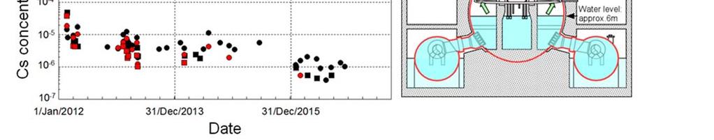
230 Figure A Changes in concentrations of Cs-137 and Cs-134 in the PCVs (Prepared based on data published by TEPCO) A-14


231 Figure A Changes in the temperature during decline of amount of water injection (Prepared based on data published by TEPCO) A-15
 Purpose: Obtaining information on \"steel grating of 1st floor in PCV\".")
 was done in April 2015 using a shape-changing robot.")
232 Appendix 4.2: Results of PCV internal survey Status of the PCV internal survey so far is summarized below. (1) PCV internal survey of Unit 1 A. Conducted in October 2012 and April ) Purpose: Obtaining information on "steel grating of 1st floor in PCV". 2) Method: The survey device was inserted through PCV penetration (X-100B penetration). PCV s internal survey by a CCD camera and stagnant water sampling were performed in October 2012, whereas pedestal outer survey (B1 survey) was done in April 2015 using a shape-changing robot. 3) Information obtained: a. No major damage to the existing facilities (PLR pump, wall surface in PVC, HVH etc.) was observed. b. Radiation dose rate on the steel grating was approx Sv/h. c. It was observed that PLR piping shielding units (lead wool mat) have fallen. It can thus be estimated that the temperature on the steel grating of 1st floor might have exceeded 328 C, which is the melting point of lead. d. Access route to the bottom of D/W was investigated, but sediments are widely distributed at the bottom of D/W. Fuel debris was not observed in this survey. Figure A Results of PCV internal survey (B1 inspection) (Unit 1) [Reference: TEPCO "Development of primary containment vessel internal survey technology pedestal survey on 1st floor steel grating (B1 survey) on-site demonstration testing results"] A-16

 and collect images and dose data. 3) Information obtained: a. Sediments were observed at the bo")
233 B. Conducted in March ) Purpose: Observation of the spread of fuel debris from the bottom of the PCV to outside pedestal as indicated in the analysis and check whether fuel debris has reached PCV shell. 2) Method: In March 2017, a remote survey device was inserted through PCV penetration (X- 100B Penetration) and a CCD camera and a dosimeter were suspended from the steel grating of 1st floor outside pedestal to carry out survey (B2 survey) and collect images and dose data. 3) Information obtained: a. Sediments were observed at the bottom of PCV and in the piping etc. b. Since the sediments did not stir up when images were taken closely the sediments, it was assumed that they have a certain amount of weight. c. The dose decreased when the dosimeter entered the water but increased when it approached the bottom of PCV. d. The height from the bottom of PCV at which the dose starts increasing varies depending on the point where it is measured. e. Radiation dose rate on the steel grating was approx. 4-12Sv/h. It has not changed much since the last inspection (April 2015) and no significant damage to the existing structure was observed. Figure A Results of PCV internal survey (B2 survey) (Unit 1) [Reference: TEPCO "Unit 1 PCV internal survey"] A-17
234 (2) PCV internal survey of Unit 2 A. Conducted in March 2012 and August ) Purpose: Observation of any fallen objects on the platform or any damage and the condition of the access route near the bottom of the PCV. 2) Method: In March 2012 and August 2013, radiation dose rate measurement and PCV internal survey with a CCD camera, and stagnant water sampling through PCV penetration (X-53 penetration) were carried out. 3) Information obtained: Dose rate varied from place to place Sv/h was measured in March 2012 and Sv/h was measured in August A survey inside the pedestal (A2 survey) in the PCV was planned, but since eluted material was found near CRD hatch (X-6 penetration) and the peripheral dose rate was significantly higher than expected values. Radiation dose reduction measures were undertaken and the survey was postponed to B. Conducted in January and February ) Purpose: The survey device was inserted through PCV penetration (X-6 penetration) and the condition of the platform in the pedestal (observation for deformations), condition of fuel debris fallen on platform and CRD housing and condition of the structure in the pedestal were observed. 2) Method: From January to February 2017, a survey was conducted by inserting a guide pipe with a CCD camera from X-6 penetration and a survey (A2 survey) was conducted by inserting a remotely operated survey device to acquire images, temperatures and dose data through the CCD cameras, thermometer and dosimeters attached to the survey device. 3) Information obtained: The remotely operated survey vehicle could not reach the platform because of the sediments on the CRD replacement rails but data such as images, radiation dose and temperature on the CRD replacement rails could be obtained. Also, images of the inside of the pedestal were obtained in the preliminary survey with a guide pipe that was conducted before inserting the remotely operated survey device. The main information obtained by this survey is given below. a. In the steel gratings inside pedestal, it was observed that had fallen out or some that had deformed so much that even the square appeared to be deformed. A lot of sediments were also seen. b. No major damage was observed to the CRD housing support near the entrance of pedestal. c. Objects were observed that seem to have stuck to the CRD replacement machine and Traversing In-core Probe (TIP) guide pipe support near it. d. Abnormalities such as cracks were not observed on the wall surface in the pedestal of the pedestal platform. e. It was observed that steam was rising from the lower part of the steel gratings. f. The maximum radiation dose rate of the CRD replacement rails was approx. 70 Sv/h. A-18
235 Figure A Results of PCV internal survey (A2 inspection) (Unit 2) [Reference: TEPCO "Unit 2 primary containment vessel internal survey - Additional inspection by image analysis"] (3) PCV internal survey of Unit 3 A. Conducted in October ) Purpose: A survey was conducted mainly to observe the condition of cool-down in PVC and also gather information that would contribute to the future study for the investigation methods. 2) Method: In October 2015, a camera, a thermometer and a dosimeter were inserted by PCV penetration (X-53 penetration) to measure the temperature and radiation dose rate. The survey for the PCV internal structures and the bottom of PCV, and sample stagnant water were conducted. 3) Information obtained: a. No damage was observed on the structure/ wall surface in PCV within the range of the observation. b. No damage was observed in CRD rail and X-6 penetration within the range of the observation. c. Sediments were observed on the CRD rail and the steel grating of 1st floor. (Transparency under water in PCV was good.) d. Water level in the PCV was OP: approx mm, which was almost consistent with the estimated value. e. Temperate inside PCV was approx C in the gas phase and approx C in the water. A-19


236 f. Dose rate of the PCV gas phase was approx Sv/h. Radiation dose in the PCV was at the lowest among Units 1-3 which seemed to be an effect of shielding caused by a high level of stagnant water. g. According to the water quality results of the stagnant water in the PCV, PCV does not have a severe corrosive environment, but rather has low corrosive environment. Currently an internal survey by inserting an ROV from X-53 penetration is under consideration to survey the inside of the pedestal in the PCV. Figure A4.2-4 Results of PCV internal survey (Unit 3) [Reference: TEPCO - Fukushima Daiichi NPS, Unit 3 Primary Containment Vessel (PCV) internal survey results] B. Conducted in July ) Purpose: Survey device was inserted through PCV penetration (X-53 penetration) to observe the status in the basement floor of pedestal. 2) Method: An underwater ROV was inserted through X-53 penetration in July 2017 to carry out survey by taking pictures. 3) Information obtained: The underwater ROV reached inside the pedestal, and it was possible to gather images of the condition inside the pedestal for the first time. The main information obtained from this survey is as given below: a. Presence of molten material that appears to have solidified was observed inside the pedestal. b. It is possible to access the inside of the pedestal through the pedestal opening. A-20
 [Reference: TEPCO, IRID Unit 3 Primary Containment Vessel (PCV) internal survey results (summary of rapid report)] (4) Stagnant water sampling results 2-6")


237 Figure A4.2-5 Results of PCV internal survey (Unit 3) [Reference: TEPCO, IRID Unit 3 Primary Containment Vessel (PCV) internal survey results (summary of rapid report)] (4) Stagnant water sampling results Figure A4.2-6 shows the analysis results of concentration of Cs-137 in the stagnant water samples collected during the main surveys inside S/C and torus room and the PCV internal survey. Since the sampling time and the units where they were collected are different, it is difficult to predict the trend of a specific unit. However, since water treated with cesium and strontium adsorption equipment has been injected into the PCV as cooling water, concentration of Cs1-37 is overall declining. Figure A shows the analysis results of concentration of Cs-137 in the stagnant water samples from the T/B, process building and high temperature incinerator building. Although there are effects of the penetrations in the T/B and the connection of drainage from the neighboring facilities, the concentration is gradually decreasing in the stagnant water in the T/B of Unit 1, Unit 2 and Unit 4. And the concentration of Cs1-37 in the stagnant water in Units 2 and 3 is showing a common tendency wherein the concentration inside of the PCV < that inside of the Torus room. A-21

238 Figure A.2-6 Concentration of Cs-137 in the sampled water (Prepared based on data published by TEPCO) Figure A4.2-7 Concentration of Cs-137 in water sampled in the T/Bs and water injection system diagram (Prepared based on data published by TEPCO) A-22
239 Appendix 4.3: Survey results of S/C and torus room Amongst the surveys conducted so far in S/C and torus room, the main status is summarized below. (1) Survey around the lower part of vent pipe in Unit 1 A. Period: November 2013 B. Purpose: Observation whether there is a water flow from the edge of vent pipe sleeve and see the condition (external observation) of sand cushion drain pipe etc. In addition, measure the radiation dose in lower part of vent pipe. C. Method: Survey with a water boat equipped with a camera and dosimeter. D. Information obtained: The following information was obtained. 1) It was observed that water was flowing down the S/C surface from the top of S/C around vent pipe X-5E. 2) It was observed that the sand cushion drain pipe around vent pipe X-5B has come off and water is flowing out. 3) Radiation dose rate was approx Sv/h. (2) Survey of the top of S/C and wall surface of torus room in Unit 1 A. Period: May - June 2014 B. Purpose: Observation for water leakage from the top of S/C near vent pipe X-5E, where a water flow was observed in the survey of November 2013 and observation for water leakage from penetration of the torus room's east wall surface. The radiation dose measurement in the torus room. C. Method: Survey using an inspection device equipped with a crawler having a camera, sonar (ultrasonic sensor) and dosimeter D. Information obtained: The following information was obtained. 1) A leakage was observed from the protective cover of the expansion joint of vacuum break line which connects to vent pipe X-5E at the top of S/C. 2) No leakage was observed in the penetrations of the torus room s east wall surface. Sonar inspection was reconsidered since the place to be surveyed was narrow. 3) Maximum radiation dose rate was approx. 2.4 Sv/h. (3) Survey in torus room in Unit 2 A. Period: April 2012 B. Purpose: Visual inspection of torus room (obtaining images), dose measurement and collecting acoustics from torus room. C. Method: Survey using a remote control robot equipped with a camera, dosimeter and acoustic device. D. Information obtained: The following information was obtained. The acoustic device could not be retrieved because communication with the remote control robot got cut off during survey. 1) Images were obtained on steel grating. 2) Maximum radiation dose was approx. 118 msv/h. A-23
240 (4) Survey in torus room in Unit 2 A. Period: April 2013 B. Purpose: Measurement of the radiation dose and temperature in torus room and obtaining images. C. Method: Survey by inserting a thermometer, dosimeter and camera through a hole opened in the floor of the RHR heat exchanger (B) room on the south side of the reactor building's 1st floor D. Information obtained: The following information was obtained. 1) Dose rate was measured at intervals of approx. 1m and the maximum dose was approx. 134 msv/h near water surface. 2) Water level was around OP (depth approx. 5.3 m). 3) Temperature was measured at the height intervals of approx. 1m. Air temperature was approx. 20 C and underwater temperature approx. 25 C. 4) Stagnant water was transparency more than approx. 100cm. 5) Although rust was found on the structure in torus room as far as it could be observed, no major damage was found. Image of the bottom part could not be obtained because it interfered with the torus room stairs at approx. 1.5 m underwater. (5) Survey in torus room in Unit 3 A. Period: July 2012 B. Purpose: Visual inspection of torus room (obtaining images), radiation dose measurement and collecting acoustics from torus room. C. Method: Survey using a remote control robot equipped with a camera, dosimeter and acoustic device D. Information obtained: The following information was obtained. The acoustic device could not be retrieved because communication with the remote control robot got cut off during inspection. 1) Images were obtained on steel grating. 2) The maximum radiation dose rate was approx. 360 msv/h. A-24


241 Appendix 4.4: Results of muon detection Fuel debris distribution was measured using muon detection technology through the transmission method for Unit 1 in 2015 and for Unit 2 in Measurement results are summarized below. Measurement for Unit 3 has been started in May (1) Unit 1 For Unit 1, fuel debris distribution was measured twice from February to May and from May to September 2015 by the transmission method of muon measurement. With the measurement results, it is reasonable to assume that no fuel fragment larger than 1 m, which is maximum muon detection capacity by transmission method or no water exist at the original reactor core region. Figure A4.4-1 Results of fuel debris measurement by transmission method of muon detection for Unit 1 [Source: Quick Report on the Measurement Results for Unit 1 from Development of Technology for Detecting the Fuel Debris Location inside Nuclear Reactors from TEPCO] (2) Unit 2 For Unit 2 fuel debris distribution was measured by the transmission method of muon measurement from March to August The following was observed from these results. It was observed that high density material believed to be fuel debris is present at the bottom of the RPV. Based on the evaluation conducted by comparing with the simulations, it was presumed that most of the fuel debris is at the bottom of the RPV. It also indicated that some high- A-25


242 density material believed to be fuel debris is present in the lower part and outer periphery of the core. However, some uncertainty in the test remains because of the effects of the reactor building's structure. Figure A4.4-2 Unit 2 Results of fuel debris measurement by transmission method of muon detection [Reference: TEPCO - Fukushima Daiichi NPS Unit 2, Locating fuel debris location by muon measurement] A-26
 ± 51%. (3) Unit 3 Muon detection has being carried out for several months since May 2017.")

243 In addition, muon radiography using nuclear emulsion counter was conducted by joint research of Toshiba corporation and Nagoya University in 2015, and by comparing the analysis value of muon count and the measured value, the residual ratio of the core part was obtained as (9 to 36) ± 51%. (3) Unit 3 Muon detection has being carried out for several months since May The current results of the evaluation being carried out indicate the possibility of presence of some fuel debris in both the reactor core region and the bottom part inside the RPV, but the presence of any high-density substance has not been observed so far. Fig A4.4-3 Results of fuel debris measurement by transmission method of muon detection for Unit 3 [Reference: TEPCO - Fukushima Daiichi NPS Unit 3, Measurement status regarding locating fuel debris location by muon measurement (interim report)] A-27
244 Appendix 4.5: BSAF project outline and results so far (1) Outline of BSAF project The BSAF project of OECD/NEA aims to improve the severe accident progression analysis code and analyze the accident progression in Unit 1 to Unit 3 of the Fukushima Daiichi NPS and their current condition to provide useful information for decommissioning of the reactors. Phase 1 was carried out with 8 participating countries (France, Germany, Korea, Russia, Spain, Switzerland, U.S.A and Japan) for 3 years from April After phase 1, phase 2 has being carried out since April 2015 with 11 participating countries (Canada, China, Finland, France, Germany, Korea, Russia, Spain, Switzerland, U.S.A and Japan). The final report will be summarized in March (2) Result of phase 1 In phase 1 of the BSAF project of OECD/NEA, 13 institutions in Japan and abroad conducted severe accident progression analysis of Unit 1 to Unit 3 for 6 days after the earthquake. Results of this analysis are shown in Table A Table A Area Result of fuel debris distribution evaluation in BSAF phase 1 [unit: ton] Unit 1 Unit 2 Unit 3 9 institutions 6 institutions 3 institutions 4 institutions 5 institutions Reactor core RPV lower head PCV (Provided by IAE) The analysis results of Units 2 and 3 were categorized into two cases, one where the fuel debris remains in the RPV, and one where it falls down to the PCV. The result of Unit 2 depends on the model of the fuel debris relocation from the reactor core to the lower plenum and the assumed amount of the water injection by the fire engine which is highly uncertain. With regard to Unit 3, the results were affected by the difference in the assumption of HPCI water injection behavior (amount of water injected in reducing the RPV pressure), that is, the maximum quantity of the steam flow rate that drives HPCI and its cycle were significantly different among the institutions that performed the analysis. (3) Status of phase 2 In phase 2, the latest knowledge is being incorporated to carry out severe accident progression analysis for three weeks after the earthquake, with an aim to make advancements in analysis. A-28
245 Also, knowledge about severe accident research analysis is being shared through workshops regarding MCCI or the state of Appendix on the FP reactor internals. Progress meetings (PRG) and workshops are held twice a year and the final report will be compiled in March A-29
246 Appendix 4.6: Characteristics of MAAP code and SAMPSON code and analysis results Characteristics of the SAMPSON code and MAAP code, the severe accident progression analysis codes, are shown in Table A and the analysis results by both codes as well as noteworthy comments about the analysis results are given in Table Table A Characteristics of MAAP code and SAMPSON code Code MAAP code SAMPSON code Developed by: U.S. EPRI Japan NUPEC (Institute of Applied Energy is continuing the development at present) Analysis targets In+Ex Vessel In+Ex Vessel User adjustment None (with dependency on mesh Multiple factor division) Calculation time Short 20 to 30 times the real time Characteristics Users can obtain the expected analysis results by combining the adjustment factors. Analysis results often differ from user to user. Analysis results do not depend on the user since it is built with a theoretical and mechanistic physical model. Verifying the individual model, code etc. User groups will continue to improve the code. Participated in OECD/NEA's international benchmark problem (ISP: International Standard Problem) and was highly acclaimed. It has also been verified by several other experimental analyses. [Reference: Koji Okamoto, Atomic Energy Society of Japan, SA evaluation research expert committee's documents] Table A Analysis results using accident progression analysis code (Implemented in FY2015) Location Unit 1 Unit 2 Unit 3 [unit: ton] MAAP SAMPSON MAAP SAMPSON MAAP SAMPSON Reactor core RPV lower head Inside pedestal 109(78) 79(130) 92(37) 76(14) 103(51) 53(20) Outside pedestal 33(52) 52(0) 102(4) 5(0) 96(6) 0(0) Total value (including concrete) Note) The weight shown for inside and outside pedestal is the fuel/ structure material weight (without concrete weight) and concrete weight is shown inside ( ). A-30
247 In Unit 1, RPV damage began before the start of water injection. Both the MAAP code and the SAMPSON code show a trend of most of the debris falling into the RPV pedestal. In Units 2 and 3, analysis using the SAMPSON code indicated that the granular particles of fuel debris were cooled by water injection and accumulated inside the RPV. At the core region and bottom of the RPV, amounts of debris estimated by the SAMPSON code are larger than that estimated by the MAAP code. In the SAMPSON code model, granular particles debris are modeled as a mass which cools down when water is present. It may be possible that the cooling water gets distributed unevenly and granular fuel debris which does not come in contact with cooling water melts again and drops on the lower plenum. Results by the SAMPSON code shows that some fuel in the outer periphery of the core has remained in stub-shape, but that is because there is water outside the reactor core shroud which is contributing towards the cooling. The fuel will melt and drop if there is no water. [Reference: IRID Completion report for "Improvement of recognition regarding the internal PCV condition using severe accident progression analysis and actual plant data"] A-31

, That is, the heat balance method means to estimate the proportion between the fuel debris in the RPV and PCV based on the assumption that the")
248 Appendix 4.7: Summary of heat balance method and estimation result The heat generation is still continued due to decay heat from the fuel debris and water injection into the RPV to cool it down. As temperature of water injection goes up to the RPV temperature and from RPV temperature to PCV stagnant water temperature, cooling has been continued with increase in temperature. Heat balance method is a method that estimates the fuel debris proportion inside the RPV and PCV assuming it maintains (balance) the state that enables decay heat (heat generation) = Sum of temperature rise of cooling water (heat release), That is, the heat balance method means to estimate the proportion between the fuel debris in the RPV and PCV based on the assumption that the temperature of the cooling water injected into the RPV is raised to the temperature of the accumulated water by the heat source (fuel debris) inside the RPV and PCV, namely the assumption that the heat input (heat of the injected cooling water and decay heat) comes into balance with heat radiation (heat radiated out to the building or into the air through the PCV walls and cooling-water temperature rise caused by fuel debris). Figure A4.7-1 is a conceptual diagram of evaluation based on the heat balance method. Shown below is the fuel debris distribution estimated by the heat balance method for each unit. Figure.A4.7-1 Conceptual diagram of evaluation by the heat balance method [Reference: IRID Completion report for "Sophistication of the internal investigation of the PCVs using accident progression analysis and actual plant data"] (1) Evaluation results for Unit 1 For Unit 1, an evaluation based on the heat balance method was performed on the assumption that no heat source exists inside the RPV (i.e., the RPV decay heat in the equation above = 0) according to the analysis results based on the MAAP code. The evaluation used the quantity of A-32


, possibility of heat release from fuel debris to the floor concrete, and")
249 the heat of the injected and leaked water calculated from actually measured temperatures of both water, with the degree of contribution of decay heat to the rise of the accumulated water temperature used as an evaluation parameter. The evaluation results indicate that if it is assumed as a heat source equivalent to 45% of decay heat, the actually measured changes in stagnant water temperature are almost reproducible as Figure A shows; thus it is determined that a significant heat source exists inside the PCV. It is, however, deemed that the fuel debris distribution is significantly affected by the uncertainty about the decay heat of the fuel debris that fell at the bottom of the PCV (according to evaluation by the JAEA, the decay heat decreases approximately 60% if all of the highly-volatile nuclides are released), possibility of heat release from fuel debris to the floor concrete, and uncertainty about the evaluation of the thermal conductivity of the heat radiation from the PCV into the outside air. Figure A4.7-2 Example of an evaluation based on the Heat Balance Method for Unit 1 (Provided by IRID) (2) Evaluation results for Unit 2 The evaluation was made based on the quantity of the heat of the injected and leaked water calculated from actually measured temperatures of both water, using as evaluation parameters the degree of contribution of decay heat to the rise of the accumulated water temperature and the ratio between the amounts of the heat sources (fuel debris) inside the RPV and PCV. A-33
 inside the RPV and PCV used as a parameter, the evaluation results indicate that if it is assumed that 30 to 60% heat source")
 (Provided by IRID) (3) Evaluation results for Unit 3 As with Unit 2, the")
250 Figure A4.7-3 shows an evaluation result example. With the ratio between the quantity of the heat sources (fuel debris) inside the RPV and PCV used as a parameter, the evaluation results indicate that if it is assumed that 30 to 60% heat source remains inside the RPV, the changes in stagnant water temperature inside the RPV and PCV are almost reproducible. Figure A4.7-3 Example of an evaluation based on the Heat Balance Method for Unit 2 (Percentage of Heat Source inside the RPV: 60%) (Provided by IRID) (3) Evaluation results for Unit 3 As with Unit 2, the evaluation was performed based on the quantity of the heat calculated from the actually measured water temperatures. Figure A4.7-4 shows an example of evaluation results. The evaluation results indicate that if it is assumed that 20 to 70% heat source remains inside the RPV, the changes in stagnant water temperature inside the RPV and PCV are almost reproducible. They also indicate, however, that since the changes in the temperature of the stagnant water in the RPV do not agree with that of the injected water, the quantity of the fuel debris existing inside the RPV as a heat source is a lower than estimated. A-34
 (4)Summary of evaluation results from Units 1-3 (Provided by IRID) Table A4.")
) Unit 2: 30-60% heat source (fuel debris) may be present in the RPV.")
251 Figure A4.7-4 Example of an evaluation based on the Heat Balance Method for Unit 3 (Percentage of Heat Source inside the RPV: 40%) (4)Summary of evaluation results from Units 1-3 (Provided by IRID) Table A4.7-1 Results of estimation of fuel debris distribution by the heat balance method Unit Estimation results Unit 1: Heat source equivalent to 45% of decay heat may be present in the PCV. (Based on analysis result by MAAP code, it is evaluated that there is no heat source in the RPV (decay heat in the RPV is zero)) Unit 2: 30-60% heat source (fuel debris) may be present in the RPV. Unit % heat source (fuel debris) may be present in the RPV. However, since the temperature of the RPV stagnant water does not follow the water injection temperature, the amount of debris present in the RPV as a heat source may be even smaller. Note: It is deemed that the fuel debris distribution is significantly affected by the uncertainty about the decay heat of fuel debris that fell at the bottom of the PCV (according to evaluation by the JAEA, the decay heat decreases approximately 60% if all of the highly-volatile nuclides are released), the possibility of heat radiation from fuel debris to the floor concrete, and uncertainty about the evaluation of the thermal conductivity of the heat radiation from the PCV into the outside air. (Provided by IRID) A-35
 was estimated based on the trend of the temperature around the RPV in the post-accident condition,")
252 Appendix 4.8: Location of fuel debris estimated from plant parameter trend The heat source in RPV (fuel debris) was estimated based on the trend of the temperature around the RPV in the post-accident condition, water temperature of S/C and amount of water injected in FDW system and CS system. Figure A4.8-1 shows the difference between flow paths of the FDW system and CS system. FDW system is a system that introduces the cooling water during the normal operation of BWR into the RPV. After flowing into the RPV, cooling water is accumulated in the space between reactor core shroud and the RPV (annulus), it will be flowing into the jet pump at the time when the water level reaches to the upper part of the jet pump mixer. If the integrity of the bottom of the RPV is maintained, the cooling water flowed in will accumulated inside the RPV and the water level the accumulated water will be raised. However, since increase in the water level was not observed, the bottom of the RPV has been damaged and the cooling water is estimated to be flown down from the damaged portion into the inside of the pedestal. That is, FDW system water injection cannot cools down the BWR reactor core portion but the bottom part of the RPV, even after the accident. While on the other hand, CS system is a core spray system in case of the loss of coolant accidents and is installed along the inner walls of the core shroud immediately above the core. In the CS system water injection, the cooling water flowing down the space from the reactor core to the bottom of the RPV and the space can be cooled down. Based on the above, the fuel debris locations were estimated for each Unit. Figure A4.8-1 Flow path of FDW and CS systems [Reference: Public data released by TEPCO] Shown below is the fuel debris distribution for each unit estimated from the trend of the plant parameters. (1) Evaluation results for Unit 1 A-36

 The ambient temperature of the RPV did not rise that corresponds to the decrease in the amount of water injected by the FDW system.")
253 Figure.A4.8-2 shows temperatures at several positions inside the PCV of Unit 1 along with changes in the quantity of injected water and measurement locations. In response to the changes in the quantity of injected water, the following characteristic changes in temperature were observed. 1) Compared to Units 2 and 3, the ambient temperature of the RPV decreased at a faster rate, which decreased below 100 C in five months after the accident. 2) The ambient temperature of the RPV did not rise that corresponds to the decrease in the amount of water injected by the FDW system. 3) With increases in the quantity of water injected for the FDW system, the ambient temperature of the RPV dropped to below 50 C and the S/C water temperature rose. 4) With decreases in the amount of water injected for the FDW system, the ambient temperature of the RPV rose. With the characteristics shown in 1), 2), and 3) above, it is estimated that the heat source inside the RPV is probably small. From 3) and 4), it is assumed that a heat source may exist in the water injection channel of the FDW system and the heat removed in response to water injection has transferred to the S/C. Figure A4.8-2 Changes in plant parameter and measurement locations for Unit 1 (2) Evaluation results for Unit 2 Figure shows the temperatures at several positions inside the PCV of Unit 2 along with changes in the amount of injected water and measurement locations. In response to the changes in the amount of injected water, the following characteristic temperature changes were observed. 1) Compared with Unit 1, the ambient temperature of the RPV is high, which was higher than 100 C even six months after the accident. 2) The temperature of the lower RPV head sensitively responded to the decreases in the amount of water injected for the FDW. 3) With the start of water injection for the CS system, the ambient temperature of the RPV decreased and the S/C water temperature rose. A-37

, 3), 4) and 5), it is estimated that a certain quantity of heat source may exist inside the RPV; from (2), it is assumed that the lower RPV head is closer to the")
254 4) With decreases in the amount of water injected by the CS system, the ambient temperature of the RPV rose. The biggest rise in temperature at this time was seen in the lower part of the RPV lower head. 5) With increase in the amount of water injected by the CS system, the ambient temperature of the RPV dropped. With the characteristics shown in 1), 3), 4) and 5), it is estimated that a certain quantity of heat source may exist inside the RPV; from (2), it is assumed that the lower RPV head is closer to the heat source than the water supply nozzle (N4B). From (3), it is deemed that the removed heat had transferred to the S/C. Figure A4.8-3 Changes in plant parameter and measurement locations for Unit 2 (3) Evaluation results for Unit 3 Compared with Unit 1, the ambient temperature of the PRV is high, which was higher than 100 C even six months after the accident; as with Unit 2, it is assumed that a certain percentage of fuel debris exists in both of the RPV and PCV. The procedure for the above estimation is shown below: 1) Compared with Unit 1, the ambient temperature of the PRV is high, which stayed at a level higher than 100 C even six months after the accident. 2) Although the amount of water injected by the FDW system is the highest in all units, the ambient temperature of the RPV decreased at a low rate. 3) With the start of water injection by the CS system, the ambient temperature of the RPV dropped rapidly. 4) With a decrease in the amount of water injected by the CS system, the temperatures of the water feed nozzle (N4B) and the RPV lower head rose. With the characteristics shown in 1), 3), and 4) above, it is estimated that a heat source may exist inside the RPV. A-38


255 Figure A4.8-4 Changes in plant parameter and measurement locations in Unit 3. (4) Summary of evaluation results from Units1-3 Table A.8-1 Results of estimation of fuel debris locations based on the trend of plant parameters Unit Estimation results Unit 1: It is likely that the heat source in the RPV is small. It is possible that heat sources are present in the flow path of water injected by the FDW system, and the amount of heat removed by water injections is transferring to S/C. Unit 2: A certain quantity of heat source may be present in the RPV. The distance to the heat source is the closer from the RPV lower head than the feedwater nozzle N4B. The removed heat is transferring to S/C. Unit 3: A certain quantity of heat source may be present in RPV. Since there is a large amount of stagnant water in the PCV there is not much change in the parameter because of which it is difficult to estimate. A-39


256 Appendix 4.9: List of properties of fuel debris The estimation result of shape of fuel debris is shown below as an example of a list of properties of fuel debris. A-40


257 A-41
 H26: IRID et al.")
 (2015) H27: IRID et al.")
258 References (Estimation of Fuel debris properties) Eidam: G. R. Eidam, Core Damage Chapter 5 of The Three Mile Island Accident, 1986 American Chemical Society, Volume 293. EPRI: W. C. Holton, C. A. Negin and S. L. Owrutsky The cleanup of Three Mile Island Unit 2 A Technical History: 1979 to 1990, EPRI NP-6931 (1990) H26: IRID et al. Operating grants for Government-led R&D Program on Decommissioning and Contaminated Water Management (Research Report of Fuel Debris Characterization and Development of Fuel Debris Retrieval Processing Technology) (2015) H27: IRID et al. Operating grants for Government-led R&D Program on Decommissioning and Contaminated Water Management (Research Report of Fuel Debris Characterization) (Interim report) (2016) (Provided by IRID) A-42


259 Appendix 4.10: Status of the comprehensive analysis and evaluation of the conditions inside the reactor in each unit A-43


260 [Reference: TEPCO Estimation of current status inside RPV and PCV at Fukushima daiichi NPS (The 2 nd International Forum on the Decommissioning of the Fukushima Daiichi NPS)] A-44
261 Appendix 4.11: Studies on containment function The accident at the Fukushima Daiichi NPS resulted in a long-term loss of power that deprived the power station of its cooling capability, resulting in a core meltdown. This was followed by the loss of the RPV and PCV containment boundaries as well as the loss of containment function of the R/B, resulting in severe environmental contamination. Under a situation where the confinement capability (boundaries) is incomplete, our critical challenge is to reduce the radiation dose and its impact, i.e., the risk level, through emergency measures, stabilization of the facilities, and cleaning after the accident. This section gives more information about the containment function such as the concept on which the power station was originally designed, what measures were taken at the time of accident, what the present situation is and what challenges are involved now that we are entering into a new phase of fuel debris removal, which is summarized below. (1)Containment function of a NPS under a normal condition In order to examine containment, its targets must be first clarified. A typical power station contains mainly two types of substances: fission products (FP) and corrosion products (CP). FPs are produced inside fuel pellets by nuclear fission. Some of it leaves the fuel pellets and is contained inside the fuel cladding. If this tube is damaged, FPs leak out into to the water, the coolant, in the nuclear reactor. Amongst the FPs, while special attention is paid to noble gas and iodine as they are likely to leak out in a gaseous state, if a leak is detected, the reactor is stopped to prevent the cooling water from being contaminated with FP, and measures are taken to replace damaged fuel assemblies. On the other hand, CPs exist in the coolant as products that are resulted from corroded structure materials, adhere to the fuel at the core, and then become liberated. The CPs that require particular attention are Co-60 and Mn-54. CPs are securely controlled with a treatment system for liquid waste to prevent them from having an impact on the outside of the power station. In addition, since they greatly expose workers to radiation, measures for reducing radiation exposure are being carried out such as use of low-cobalt materials as structural materials, improvement of reactor water chemistry, and removal of corrosion products. During normal operation, the FPs and CPs mentioned above, including small amount of leaks, are kept within the radiation controlled area and treated with a waste treating system to ensure that they are below the reference value before they are released. During scheduled outage, RPV and PCV are opened and the reactor well is filled up with water to replace the fuel and inspect the inside of the reactor. In this case also FPs and CPs are kept within the radiation controlled area and treated with a waste treating system to ensure that they are below the reference value before they are released. Radioactive dust may be a problem A-45
262 during construction, and therefore its release from the radiation controlled area is restricted by setting up barriers or separate air-conditioning etc. (2)Containment function at the time of accident Originally, the containment function is expected to prevent FPs from being released when an accident occurs. As a containment function, FPs are contained by 5 layers of walls: (1) fuel pellets, (2) fuel cladding, (3) reactor coolant-pressure containment boundary (RPV containment boundary), (4) primary containment vessel (PCV containment boundary), and (5) R/B (secondary containment). Out of these containment functions, the RPV boundary is for containing liquidphase and the PCV boundary and R/B are for containing gas-phase. In order to prevent hydrogen explosion in BWR plant in the event of an accident, the PCV is filled with nitrogen and inactivated during operation. According to the scale of the accident, the release is prevented by the fuel cladding tube, RPV boundary, or PCV boundary. Various accidents at BWR plants so far have not resulted in significant core damage caused by core re-submersion. This even applies to an accident that undergoes a guillotine break of the RPV boundary piping resulting in a loss of the coolant. If an accident occurs, for the liquid phase, a circulation loop is established as a boundary that allows cooling water that has flown out from the ruptured part to move to the S/C and then be poured into the reactor by the ECCS system. Regarding the PCV gas phase part, while containment is maintained, radioactive substances leaking at slightly below the allowable value are retained inside the R/B and released while being processed in an emergency gas treatment system. Regarding this, the dose standard for accidents at the site boundary is determined as 5 msv / accident. The accident at the Fukushima Daiichi NPS, however, resulted in a long-term loss of power, leading to conditions more severe than those assumed in the design phase. The loss of the cooling capability of the reactors and the damage to the cores resulted in losses of two walls: (1) fuel pellets and (2) fuel cladding tube. Furthermore, the molten core damaged the RPV, resulting in a loss of the (3) RPV containment boundary. Subsequently, the temperature and pressure inside the reactor containment vessels became high, which damaged the (4) PCV containment boundary, causing leakage of steam containing radioactive substances and hydrogen, produced by a water-zirconium reaction, into the R/B. Since the standby gas treatment system did not work either due to the loss of power, hydrogen explosions and other factors damaged the (5) R/B. However, although damaged, the PCV still existed which suppressed the release of gases other than highly volatile gases such as the noble gas and iodine. Although the reactor core melting could not be avoided, reactor core cooling was possible. This development was never seen in Chernobyl. A-46
263 As a result, the release of cesium to the air outside the PCVs was controlled under 2%. For the other nuclides, the release amounts were even lower. On the other hand, it is necessary to keep pouring in water to cool the fuel debris but that water leaks out from the breakages in the PCVs. This causes radioactive substances contained in leaked water to continuously flow out and mix with the stagnant water in the buildings, which presents a problem of contaminated water caused by degradation of the containment function for the liquid phase. Since the R/B s water seal function has also degraded, the ground water keeps flowing in and increases the contaminated water. This has further complicated the problem. To prevent contaminated water from increasing and radioactive substances from flowing out to the outside of the system, a cooling water injection system is used that purifies contaminated water and then reuses it to cool reactor cores with the building used as a boundary. The level of the accumulated water inside the building is kept lower than that of ground water so that ground water will flow in (in leak) so as to prevent radioactive substances from flowing out (out leak) to the outside of the building. This continuous water injection successfully cooled fuel debris and sufficiently decreased the temperature inside the containment vessels to below 100 C. This remarkably suppressed the release of radioactive substances, achieving a so-called stable cold shutdown state. (3)Containment functions at the Fukushima Daiichi NPS at present The present containment functions at the Fukushima Daiichi NPS is as follows. The containment function for the liquid phase uses a cooling water injection system that purifies the water accumulated inside the building using a water treatment system and then reuses the purified water to cool the reactor core with the PCV used as the primary boundary to retain cooling water poured into the reactor and the building used as the secondary boundary to retain water leaked from the PCV. The level of the accumulated water inside the building is kept lower than that of ground water so that ground water will flow in (in leak) so as to prevent radioactive substances from flowing out (out leak) to the outside of the building. This causes the ground water that has flowed into the reactor to be redundant water, which must be stored as water treated by the water treatment system. This requires a storage tank to be kept inside the premises, which presents a problem with contaminated water. To counter this problem, subdrainage equipment is installed near the building to pump up ground water and release it into the harbor through a purification system, thus lowering the level of ground water to reduce the amount that flows into the building. Multiple layers have also been set up by putting up land-side impermeable walls to reduce the groundwater near the R/B. Transfer system for stagnant water inside the building is also installed so that the level of the accumulated water inside the building can be controlled. To reduce the amount of ground water that comes in and prevent contaminated water A-47
264 from flowing out, it is required to be able to securely control the level of water inside and outside the buildings under any condition. As for boundary for the gas phase, a nitrogen filler is used to inactivate the inside of the PCV and a PCV gas monitoring system is installed to extract gases inside the PCVs, filter them, and measure radiation from them before releasing them. This arrangement keeps the pressure in the gas phase slightly positive to prevent a hydrogen explosion and minimizes the release of radioactive substances. With these measures, the estimated radiation dose at the boundary of the premises due to the radiation released from Units1-4 is sufficiently low--approx msv/year. (4)Issues concerning the containment function during the fuel debris retrieval work Removal of fuel debris involves cutting the debris, which probably causes α fine particulates to move to the liquid or gas phase inside the PCVs. In addition, changing the level of water inside the PCV is being considered, meaning that the requirements for the containment function may change. For alpha particulates, the upper limit of concentrations associated with internal exposure through inhalation, in particular, is stricter than that for the other nuclides. For this reason, attention must be paid to particulates that may be released as dust from the gas phase and the gas-phase containment boundary must be arranged based on careful consideration. Hence, it is easier to control the alpha particles if they are moved to liquid phase by doing the task of cutting fuel debris under water or with pouring water as far as possible. In this case, raising the level of water inside the PCVs must be considered. This is one of the major aims for which intensive R&D for PCV repairs (water sealing) is in-progress at present. Regardless of the fuel debris retrieval method, alpha particles are basically being converted to the liquid phase wherever possible, which inevitably raises the concentration of radioactive substances in the liquid phase. This raises an issue of how to build a liquid phase containment function while considering the current control for the difference in the water level between the inside and outside the R/B. As for the containment function for the gas phase, although an action is taken to convert alpha particles to the liquid phase as much as possible while removing fuel debris removal, the concentration of alpha nuclides in the gas phase is expected to increase. Now the challenge is to develop a system wherein a cell is installed in the upper part the PCV to keep the inside pressure negative (primary containment boundary) while a container is also installed in the R/B to set up an air conditioning system that controls the inside pressure to keep it negative (secondary containment boundary). While developing these containment functions, not only normal operations but measures in the event of an emergency must also be considered. A-48
265 Appendix 4.12: Study of water level at the bottom of PCV when retrieving fuel debris Assuming that it is possible to control water level by installing of underwater pumps, water level at the time of fuel debris retrieval at the bottom of PCV is illustrated and explained by dividing into two cases, that is, achieving and not achieving vent pipe water seal *1 (Fig A4.12-1). The upper part of the diagram shows the current water level, the middle part is the conceptual diagram when water sealing in the lower PCV has been achieved by vent pipe repairing, and the lower part is the conceptual diagram when water sealing of vent pipe could not be achieved. It is necessary to setup and control the water level depending on the success or failure of the repairs to the vent pipe. *1: Inability to perform water sealing for vent pipe also includes the cases in which water seal technology cannot be applied at on-site as construction is not possible due to high dose of radiation. [Water level at the bottom of PCV in Unit 1] When water sealing of vent pipe successful - The expected water level when water sealing for vent pipe is done is shown in the middle part of the diagram. The water level in the PCV can be maintained to the present level (about 2 m from the bottom of PCV), and fuel debris retrieval can be carried out underwater. In order to improve the seismic resistance margin of S/C while retrieving fuel debris, it is preferable to dry up the inside of the S/C (if it is dried up in the beginning, that state can be maintained). If the water level in the PCV lowers, it can also be carried out in a state of partial submersion where water is poured in. In case water sealing for vent pipe could not be done, water sealing of strainers are carried out since downcomer water seal has a poor seismic margin. From the viewpoint of seismic resistance of S/C, it is desirable to continuously dry up the inside of S/C. As shown in the lower part of the diagram, water level of bottom part of PCV cannot be maintained. For example, it will be low as in Unit 2 (About 0.3 m from the bottom part of PCV). Therefore, the fuel debris retrieval is carried out in partial submersion state with water being poured in. [Water level at the bottom of PCV in Unit 2] If vent pipe water sealing is done, it is possible to increase the water level at the bottom of PCV. For example, if the level is set at current level of Unit 1 (approx. 2m from the bottom of PCV), it will be possible to carry out fuel debris retrieval under water. It will also be possible to carry out work under partial submersion, with water being poured in, by maintaining the water level inside PCV in the current state. If vent pipe water sealing cannot be done, one method to stop water could be to apply a downcomer water seal in which high-flowing concrete is poured into S/C to bury the tip of the down comer and A-49
266 separate the D/W and S/C. The performance of downcomer water seal has been confirmed by testing, but its seismic resistance, although promising, needs to be confirmed in future detailed testing. Also, though leakage from S/C is expected in Unit 2, prevention through water sealing method will be planned. Fuel debris retrieval work is done underwater or in a state of partial submersion where water is poured in. The lower part of the diagram shows retrieval tasks being carried out under water. [Water level at the bottom of PCV bottom in Unit 3] If vent pipe water sealing is done - If side access method is to be adopted, the current water level (approx. 6m from the bottom of PCV) needs to be reduced to the current level of Unit 1 (approx. 2m from the bottom of PCV) (middle stage in the diagram). In this case, it will be possible to carry out fuel debris retrieval work under water. However, it is necessary to obtain technical support for keeping this water level stable during the retrieval work. It will also be possible to lower the water level further and carry out the task in partially submersed state with water being poured in. If vent pipe water sealing is cannot be done - Like Unit 2, a water sealing method that can be considered is to apply downcomer water seal for separate D/W and S/C. Fuel debris retrieval work is done underwater or in a state of partial submersion where water is poured in. The lower part of the diagram shows retrieval tasks being carried out under water. A-50
")


267 Figure A Water level at the bottom of PCV and water sealing for vent pipes (Conceptual diagram) The current water levels inside PCV are: Unit 1: water depth of about 2m; Unit 2: water depth of about 0.3m; Unit 3: water depth of about 6m. If water sealing can be achieved in vent pipes, the task of retrieving fuel debris can be performed under water in each unit. The water level inside PCV is controlled by operating the circulation system from D/W for raising the water level of Unit 2 or lowering the water level of Unit 3. If the water level has been lowered, the task can be carried out in partially submersed state with water being poured in. If vent pipe water sealing is not done, strainer water seal is applied in Unit 1, and water A-51


268 Appendix 4.13: Preliminary Seismic Margin Evaluation of RPV and PCV. A-52


269 A-53


270 A-54


271 A-55


272 A-56


273 A-57


274 A-58


275 A-59
 Test with a hydraulic manipulator Checking the basic feasibility of the")
 based on the assumption that a long distance is required between the fluid-pressure controller and access unit when the latter")
 Evaluation and challenges Objective Tests up to FY2016 complete.")
276 Appendix 4.14: Development of fuel debris retrieval equipment and devices Objective Test details (1) Test with a hydraulic manipulator Checking the basic feasibility of the control characteristics helpful in designing a manipulator for removing fuel debris, and identifying their challenging items Present situation Evaluating the effect of the hose length (10 m or 100 m) based on the assumption that a long distance is required between the fluid-pressure controller and access unit when the latter must be remotely controlled Evaluating the effect of the load (15 kg) to be mounted at the end of the manipulator Setting the moving speed of the laser end as the operating speed (2 mm/second or so) Evaluation and challenges Objective Tests up to FY2016 complete. It was possible to confirm the basic features of fuel debris retrieval manipulator. For practical application, it is necessary to verify its controllability, considering its use in combination with tip tools. Overview A-60


277 Designation Objective (2) Technical developments for cutting/dust collection, visualization and measurement For easy removal, fuel debris must be processed into easy-to-handle sizes. Identifying the characteristics of cutting technologies that seem to be effective for fuel debris processing and developing technologies for collecting dust and aerosols produced during processing Test details Developing a radiation-proof camera to be used in the environment of fuel debris removal Improvement bit: Checking the stability in early stages of cutting and the amount of chips to be produced, and verifying the processibility of the mock fuel debris Non-core bit: Checking the processibility of mock fuel debris Laser: Measuring the processing efficiency and the weight and the particle size distribution of secondary products (fumes) moving into water and air Analytic evaluation to select a method for preventing fumes that move into the air from spreading Checking the effect of removing fume from gases Present situation Evaluation and challenges Overview Camera: Irradiation test on the pickup camera tube and radiation-resistant camera Tests up to FY2016 complete. With respect to cutting technology, it was possible to verify cutting performance using laser and boring. With respect to visual component, irradiation test of imaging tube and radiation-proof camera was conducted and its resistance against radiation was verified. Specific equipment needs to be designed (including combinations with robotic arm etc.) for application at on-site. It is necessary to continue studies on an efficient dust collection technology. A-61
 Test details Prototyping a 1/1 scale element of the lower")
 Prototyping an upper table and conducting a test on it in or after")

278 Designation Objective (3) Development of the devices to access to the inside of the RPV Developing a device that brings the fuel debris handler handing device nearby fuel debris and supports the reaction force during fuel debris removal (processing and collection) Test details Prototyping a 1/1 scale element of the lower table, which is a common platform for work inside the RPV Checking the basic action of the support mechanism as well as the performance of remove at a (single) malfunction Identifying the most appropriate supporting method (contact or pressing support) Prototyping an upper table and conducting a test on it in or after fiscal 2017 reflecting the design conditions, such as the interfaces cell Present situation Tests up to FY2016 complete. Verified the basic feasibility of the concept by producing a test specimen of the device to RPV. Evaluation and It is necessary to verify workability (mockup test etc.) assuming specific tasks. challenges Overview A-62


279 Designation Objective (4) Development of platform/cell Developing a system that contains the radioactive substances generated from the PCV and shielding from radiation by using a floor door installed between the cell installed on the refueling floor and the PCV Test details Prototyping a 1/1 scale element of the shielding port Checking the action of the opening/closing door Checking the airtightness of the seal Present situation Tests up to FY2016 complete. By creating prototype of the actual scale of the platform/cell, it was possible to verify the operation of closing door and shielding door inside the cell and the airtightness. Evaluation and challenges Installation feasibility and remote maintenance performance etc. needs to be studied for practical application. Overview A-63


280 Designation Objective (5) Development of handling equipment for fuel debris canister Developing equipment that can be remotely controlled to transfer container cans to the RPV, close the lids, and clean the surfaces of the cans Testing details Prototyping a 1/1-scale element of a device for closing the lids of container cans Checking the basic action of the bolt tightening mechanism Checking the appropriate tightening method and procedure Checking the easiness of removing, disassembling and carrying out for maintenance of the remote device Present situation Tests up to FY2016 complete. It was possible to verify sealing and remote operation performance with the test specimens for canisters and sealed containers closing mechanism and closing jig. Evaluation and challenges Design conditions have been determined for the equipment for handling canisters. But, it must be designed by maintaining its consistency with the entire removal system. Overview A-64


281 Designation Objective (6) Development of light-weight and shape-following shielding Developing equipment for facilitating installation and removal of a shield to be installed between the refueling floor and PCV in the upper-access method Test details Reviewing the required strength through stress analysis based on distortion simulation Reviewing the removing and recovering method a installed water-filled shield Reviewing the shape of the drainage nozzle and drainage pressure conditions Present situation Tests up to FY2016 complete. It was possible to verify installation and removal by remote operation and verify the basic feasibility with 1/4 scale model. Evaluation and challenges Overview It is necessary to establish an exact method for verification of tasks etc. for on-site application. A-65


282 Designation (7) Development of utilizing films and sheets for contamination spread prevention method Objective Developing equipment for partitioning work areas and preventing radioactive dust from spreading removal of large structures Test details Checking the mechanisms of equipment for preventing contamination from spreading, large opening/closing equipment, and remote equipment using models of an approximately 1/4 scale model of the actual equipment and checking the operating procedure for the equipment Checking the airtightness of film and sheet to be used as partitions between areas Checking the weldability and airtightness of contaminated equipment during cure Present situation Tests up to FY2016 complete. Verified the performance by testing characteristic of films and sheets and verified the work procedure 1/4 scale model. Evaluation and challenges It is necessary to establish an installation method that is suitable for on-site application. Overview A-66


283 Designation Objective (8) Development of sealing technology for devices accessing to the inside of the RPV Developing equipment for preventing radioactive dust spreading at access unit and also at the interface between the access unit and RVP, in the in-air upper access method Test details Checking the sealing performance by partial simulation tests (including tests on slewing and opening and closing of the port) using a full-scale model Checking the sealing mechanism inside the RPV Checking the sealing mechanism at the bottom of the equipment Present situation Tests up to FY2016 complete. It was possible to verify the feasibility of basic prevention of radioactive dust dispersion and certain sealing performance. Evaluation and challenges It is necessary to check the impact on performance when combining remote-control operation procedures and maintenance method and the in-furnace work equipment for onsite application. Schematic drawing Overview A-67

 Checking whether a rail can be installed remotely Checking the accessibility to the inside of the pedestal Checking the cutting action inside the pedestal")

284 Designation Objective (9) Development of device to access inside the pedestal Checking the basic feasibility of a series of processes from installation of an access rail inside the pedestal to cutting of fuel debris using a robot arm the horizontal access method Test details Checking the positioning accuracy of the robot arm (in with the conditions of end load of 2 t and an arm length of 6.5 m) Checking whether a rail can be installed remotely Checking the accessibility to the inside of the pedestal Checking the cutting action inside the pedestal Present situation Tests up to FY2016 complete It was possible to verify the basic performance of access equipment within pedestal contributing to the design of practical application prototype machine. Evaluation and challenges It is necessary to verify the controllability in combination with advanced tool, proceeding with the verification of installation method of robot arm at on-site and maintenance method. Overview A-68


285 Designation Objective (10) Development of flexible structure arm for remote-controlled work Developing the arm and its ancillary devices for removing obstacles that block fuel debris removal work inside the PCVs for the horizontal access method Test details Checking the accessibility, remote operability, and handleability by using mockup facility simulating the condition of the pedestal inside Conducting element tests with the in-air horizontal removal method in mind to check the applicability of the method under review for removing fuel debris and devices Present situation Tests up to FY2016 complete. It was possible to verify the operability of the remote operation using prototype and handling etc. Evaluation and challenges Overview It is necessary to study work methods and maintenance techniques to match the condition of the site and confirm the plan for removal of interfering objects within PCV. A-69


286 Designation Objective (11) Development of the PCV remote seal welding equipment for cells Developing welding equipment for building boundaries between the cell being installed at a side of the PCV and the PCV connection in the horizontal access method Test details Checking the feasibility of welding for the narrow section simulating the actual working conditions Checking the quality of cross sections of welds Checking the tensile strength of weld samples Weld performance of 30-m hydraulic head pressure (0.3 MPa) Present situation Tests up to FY2016 complete. It was possible to verify the basic design feasibility necessary for PCV and cell boundary construction. Evaluation and challenges Overview In order to apply this on-site, it is necessary to study regarding specific work procedures and how to ensure welding quality etc. A-70
287 Appendix 4.15: Risks accompanied by fuel debris retrieval tasks During fuel debris retrieval, there are risks such as abnormal radioactive material leakage accompanied by the tasks, hence in order to carry out the task safely, it is important to conduct risk analysis and have clarity on improvement points in advance, then take them into account of reviewing methods in future. Further, the risk here is defined as the influence and likelihood of released radioactive material as a result of events that can be assumed during debris retrieval. (2)Risk assessment method Since installations and procedures for fuel debris retrieval are not decided, experts with experience in TMI-2 accident and decommissioning of Hanford facility evaluated the risk based on their engineering judgment with the following procedures. A. Assume an overview of installations and procedures. B. Determine the types of events that can be expected (refer to (2)), and use the knowledge of engineering to define the likelihood of their occurrence in 5 stages (historically occurrence is rare - not expected to occur even without prevention measures taken - occurs once if preventive measures are not taken.) C. Considering the distribution and properties of fuel debris, environmental conditions (on the surface of the water, submersion) where fuel debris is placed, the release route assumed in the event, etc. evaluate the dose that the public receives from inhalation and seafood intake as well as the dose that that the workers receive from inhalation and direct ray respectively based on released amount and judge in five stages (engineering judgment by experts when quantification is difficult) ((Can be ignored Cannot be ignored but less than normal dose standard At normal dose standard level.) D. Evaluate risks in five stages based on their likelihood of occurrence and impact. (2)Events which can be expected (refer Table A4.15-1) Firstly one of the possible events in which radioactive materials could be released while retrieving fuel debris are assumed, is a case in which the enclosed contaminated gas and liquid may be released. Also, like the event mentioned above, leakage of radioactive dust caused by falling of heavy objects can be considered. Besides these, release by criticality or hydrogen explosion can be considered. (3)Evaluation results and risk reduction. The result of applying method (1) to the event (2) is shown in Table A Since the effect of dust dispersion prevention achieved by flooding by partial submersion method is small, there is an increase in radioactive material concentration in the air which increases the risk as the in impact at the time of contaminated gas outflow increases. A-71
288 In submersion method, the PCV water level is increased as part of preparation, fuel debris is flooded and there is a possibility of becoming critical. Also, lot of fuel debris comes in contact with water which generates hydrogen due to radiolysis and the hydrogen concentration increases since the gas phase section is small. This leads to an increased risk as it increases the possibility of a hydrogen explosion. There are two ways to reduce risks, i.e. reduce the impact and possibility of occurrence. In order to effectively reduce the risk, it is better to reduce high impact or possibility of occurrence which is a major cause of the risks. As an example of mitigation measures in the event of outflow of contaminated gas, installation of a cutting particles collection system for reducing concentration in the air and an installation of a filter to a negative pressure control system are considered. As an example of measures to prevent criticality, installation of sub-critical state monitoring and neutron absorber injections are considered. And as for the measures for preventing hydrogen explosion, scavenging with inert gas and monitoring the hydrogen concentration are considered. Further, considering risk in terms of environmental pollution rather than exposure, there is higher risk in the event of large amount of radioactive materials emission, especially events with large release of liquid that are more difficult to diffuse than gas. Considering cases in which large amounts of liquid radioactive material is released into the environment, one possible scenario is where there is an outflow due to some catastrophic failure such as PCV damage. Especially, in case of submersions method, the risk is higher because the amount of water held in PCV is more than the partial submersion method. Characteristics of these risks and countermeasures are generally consistent with Section 4.5 "Considering feasibility of fuel debris retrieval methods". Since it is believed that this method can be used in future to realize methods or verify the safety of preparatory tasks, the study on this will be continued. Event type Outflow of contaminated gas Falling of heavy objects Outflow of contaminated liquid Table A Example of specific events Example of specific events Incorrect connection of exhaust installations, loss of confinement function due to erroneous operation, outflow due to exhaust installation failure, outflow due to disturbance in exhaust balance, outflow caused by installing an opening in PCV (only for side removal), HEPA filter damage. PCV shield plug falling, PCV head falling, RPV head falling, dryer or separator falling, RPV internal structure falling on operating floor, fuel debris falling in CRD housing due to cutting of the fuel debris in RPVRPV, fuel debris falling on pedestal due to cutting of the fuel debris in RPV on CRD housing, RPV lower head falling due to cutting of it to remove pedestal's fuel debris (top access method).) Outflow due to small piping damage, outflow due to large piping damage, outflow due to catastrophic failure such as PCV damage, outflow due to tsunami (only for side access method) A-72
289 Event type Criticality Hydrogen explosion Example of specific events Criticality due to cutting fuel debris re-assembly in critical shape inside water, criticality due to re-assembly of cutting particles after movement, criticality due to rising water level (only in case of submersion method), criticality caused by an increase in the water level by mistake (only in case of partial submersion method), criticality caused by gathered fuel pieces Explosion by hydrogen accumulation due to ventilation airflow blockage, explosion due to hydrogen release from fuel debris, explosion due to hydrogen accumulation in piping. Table A Main causes of risk and examples of risk reduction measures Event type Outflow of contaminated gas (including dust due to falling of heavy weight object) Outflow of contaminated liquid Criticality Hydrogen explosion Main causes of risks and examples of risk reduction measures Since the effect of dust dispersion prevention achieved by flooding is small with partial submersion method, concentrations in the air increase and the impact during outflow increases. As a measure to mitigate the impact for reducing airborne concentration, setting installing cut particles collection system and setting up filters in negative pressure control systems are considered. Even if contaminated liquid in the building or piping containing the radioactive material flows out in the site, measures such as the installation of seaside impermeable wall are taken and the possibility of outflow to ocean is low. Even if it is assumed that direct ocean outflow is made, the effect on the public is extremely small due to the diffusion effect in the ocean. When PCV water level is raised as preparation for submersions method, fuel debris is flooded and there is possibility of becoming critical. As a preventive measure, subcritical state monitoring and neutron absorbing injection are considered. In submersion method, lot of fuel debris comes in contact with water, which generates hydrogen due to radiolysis and the hydrogen concentration also increases since the gas phase section is small. Compared to partial submersion method, there is increased possibility of a hydrogen explosion. As prevention measures, scavenging with inert gas and monitoring hydrogen concentration are considered. A-73
\" from the 42nd meeting of the Reactor Decommissioning and Contaminated Water Countermeasures Team of May 25, 2017.")
290 Fig. A5-1 Management status of rubble, etc. and secondary waste from water treatment Source: Tokyo Electric Power Co., Inc., Document 3-4, "Management Status of Rubble and Felled Trees (as of April 30, 2017)" from the 42nd meeting of the Reactor Decommissioning and Contaminated Water Countermeasures Team of May 25, Appendix 5: Status of Solid Wastes Management, and Their Storage Management Plan A-74
291 A-75 Fig. A5-2 Overall schematic of the storage management plan for solid waste from the Fukushima Daiichi nuclear power station. Source: Tokyo Electric Power Co., Inc., Document 3-4, p. 22, "Tokyo Electric Power Co., Inc. Solid Waste Storage Management Plan from the Fukushima Daiichi Nuclear Power Station (Revised in June 2017)" (body text) from the 43rd meeting of the Reactor Decommissioning and Contaminated Water Countermeasures Team/bureau conference of June 29, 2017.
292 Appendix 6.1: Interim Report by Research Partnership Task Force (Tentative translation) November 28, 2016 Research Partnership Task Force 1. Background The Technical Strategic Plan for Decommissioning of the Fukushima Daiichi Nuclear Power Station of Tokyo Electric Power Company 2016 ( Technical Strategic Plan ) points out that it is important to create research plans that target whole of the phases from basic/generic research to the applied research and the practical development by broadening our horizons to include the technical development issues from the strategical viewpoint and by widely collecting those basic and generic technologies that are thought to be necessary in the future. At present, the main budgetary measures by the Government related to the research and development to foster the decommissioning of the Fukushima Daiichi Nuclear Power Station (1F) are the Project of Decommissioning and Contaminated Water Management (the National Project ) by the Ministry of Economy, Trade and Industry (METI) and the Center of World Intelligence Project for Nuclear S&T and Human Resource Development ( World Intelligence Project ) by the Ministry of Education, Culture, Sports, Science and Technology (MEXT). The International Research Institute for Nuclear Decommissioning (IRID), the Japan Atomic Energy Agency (JAEA), research institutes such as universities, etc. are carrying out research and development projects that are thought necessary while Tokyo Electric Power Company (TEPCO) Holdings is also carrying out their own required research and development. On the other hand, the 1F decommissioning project, which may continue for 30 to 40 years long, currently has many uncertain and unclear issues and thus the whole image of the needs for research and development considering the time base is not clarified yet. Thus, since systematic search for seeds is not easy, it seems that there are many potential research seeds that are still not investigated. Therefore, NDF launched a Research Partnership Task Force consisting of a small number of experts in order to identify, evaluate and prioritize the further research and development issues and needs on which we should work in a strategic and preferential manner toward decommissioning of 1F, and the task force had discussions. 2. Basic Ideas 2-1. Necessity of understanding of principles and investigations based on theories The technically difficult issues include those that can be cleared by application of the existing technologies only if time and cost are spent and those that can be cleared by understanding of the universal principles lying in the backgrounds of the phenomena and by investigation based on the theories. In the future device development, etc., we should stand on these scientific investigations for achievement of the spec targets, etc. in order to firmly drive the development without having A-76
293 critical problems and large delays. In other words, in order to foster the 1F decommissioning project that will last for years long, it is required to plan a mid-and-long-term research and development strategy including understanding of the principles and scientific investigations of the theories as above mentioned. For the basic researches related to the 1F decommissioning project, on the other hand, the project configuration is based on consciousness of the needs, such as participation of the NDF in the proposal selection and the interim evaluation. To prevent the selected tasks from configuring only by following the conventional research themes on the side of the seeds (adopted organizations), it is expected to produce achievements that are more conscious of the applicability to the 1F decommissioning site Clarification of needs and search for seeds The 1F decommissioning project takes 1F only as its target to which the technologies are applied but on the other hand, it is a comprehensive engineering derived from a variety of scientific and engineering technologies and knowledge including nuclear physics, chemistry, machinery, architecture, physical properties and measurement. The potentiality of the seeds is unlimitedly open. The task to find the prospective seeds from them requires wide knowledge, critically high judgment, and a great deal of labor. Therefore, it is the most certain and efficient way that some experts who are familiar with both the site condition of the 1F decommissioning project and the responses to the reactors damaged by the accident firstly extract various scientific and engineering issues (hidden needs) that may become critical in the future in the 1F decommissioning project from the medium-to-long term viewpoint, and then proceed to search for the seeds based on those issues. 3. Methods The Platform of Basic Research for Decommissioning (secretariat: Collaborative Laboratories for Advanced Decommissioning Science (CLADS), JAEA) has been breaking down and systematically organizing the needs while creating an R&D map to clarify the relationship between the needs and the seeds. These activities correspond to the above-mentioned idea and therefore, it seems appropriate to continue our actions by using the Platform of Basic Research for Decommissioning as the basis. The Platform of Basic Research for Decommissioning should found a task subcommittee (provisional name) consisting of experts from both the needs side including TEPCO and the seeds side including universities, etc. for Essential R&D Themes extracted as an issue that could be critical in the future in the progress of the decommissioning project. It should be investigated mainly by comprehensive system integrators or candidates who can be a communication hub between the A-77
294 both needs and seeds sides with a panoramic perspective and integrate the technical seeds and bring them to the practical phases. This R&D strategy should suppose to found a system that forms a COE centered with core personnel or core studies and it would continue to engage with the project for a long time in order to support the long-term 1F decommissioning. As contents of the strategy, we expect a composition of concrete core research themes (research scopes) and approaching methods thereof for application to the 1F decommissioning project, i.e., a comprehensive R&D strategy that considers a research conducting system centered on a COE, research facilities and equipments, development of young human resources through appointing them as a core personnel and promoting research, implementing timeline and achievement target that are calculated by considering the Mid- to Long-Term Roadmap, the technical strategic plan, and the needs, a desired way of research evaluation, and a required budget, with consideration on the international situation of the R&D. In this case, since these are R&D planning that are generally made by researchers, it is desired that the task subcommittees be operated by R&D institutions, etc. that have special knowledge of each task field. In addition, these institutions should collaborate with the NDF and the Research Partnership Task Force to go on while fully considering the needs. What is expected to TEPCO are to send persons as the above mentioned experts on the needs side who are familiar with the 1F decommissioning site and can sufficiently communicate with the experts on the seeds side from each fields, and to take consideration that these persons will be able to play their roles for a long time as core personnel on the needs side. 4. Essential R&D Themes Based on the above mentioned points, while considering the logic tree in the technical strategy plan, etc., the Research Partnership Task Force discussed the essential R&D Themes on which we should work strategically and preferentially for clarification of principles. As a result, the task force extracted the 6 themes for now as shown on the table and identified the related technical seeds. Note that some other essential issues remain including the remote controlling techniques and the storage and disposal of fuel debris. Therefore, we will keep extracting the essential R&D themes. These Essential R&D Themes have different levels of specification of research scope, different emergency levels, different timelines of application, and different research periods. Therefore, considering these points, the above-mentioned task committees should review the R&D strategy in a flexible and agile manner. If necessary, NDF should start initial R&D activities within this fiscal year (FY2016). In addition, based on the intent of this interim report, the Governmental and related institutions are expected to start or support the R&D actions and to consider a system that is necessary for carrying out this R&D strategy in a more effective manner. A-78
295 6 Essential R&D Themes that should be worked on for the clarification of principles in a strategic Essential R&D Themes To identify process of characteristic changes in fuel debris over time To elucidate corrosion mechanisms under unusual/extreme circumstances Radiation measurement technologies adopting innovative approaches To clarify behavior of radioactive particulates generated during decommissioning (incl. alpha dust treatment) To understand fundamentally mechanisms of radioactive contamination Environmental fate studies of radioactive materials generated during decommissioning and preferential manner Descriptions / Background issues The fuel debris retrieval is scheduled for 2021 onward, 10 years after the fuel debris production. And since it is anticipated that the retrieval will require a long period of time, the fuel debris will remain inside the reactors over 10 years. We also need to remember that the retrieved debris must be stored safely. Choosing the best possible methods of retrieve/transmission/storage of fuel debris requires predictions of characteristic changes of fuel debris over time. It is required to collect data on corrosion under a variety of circumstances with consideration of the circumstances specific to 1F decommissioning such as high radiation levels and unsteady routes of cooling water in order to prepare for potential corrosion during decommissioning. The radiation levels are still extremely high inside the 1F reactors/buildings due to the accident and the existing measurement devices do not meet the capability/functional requirements to provide accurate figures. It is vital to develop an innovational device adopting brand-new ideas/principles based on 1F needs. As thermal cutting of the fuel debris via machine or Laser may produce a large amount of alpha dust, it requires safety measures and dust containment solutions. It is necessary to understand physical/chemical properties of alpha dust, to predict the amount of dust to be produced for each method, and to consider how to seal the dust according to the results in order to make sure the retrieval will be conducted in a safe and effective manner. To figure out the mechanism of radioactive contamination towards effective decontamination; it is critical to implement effective approaches of decontamination based on the mechanism of the contamination to radiation sources, and to decrease the volume of radioactive wastes as well. It is essential to clarify the behavior of radioactive materials such as absorption, dispersion, moving along with groundwater flow in shallow underground in order to conduct environmental fate studies to ensure they will not affect the environment. (Note) The Descriptions/Background issues describes the contents of the issue that the Research Partnership Task Force suppose at present. Compositions of research theme (scopes of study) and the methods of approach should be established in a more concrete manner in the R&D strategy by the task subcommittees. (Reference 1) Members of Research Partnership Task Force Koji Okamoto Professor, Graduate School of Engineering, The University of Tokyo Toru Ogawa Director, Collaborative Laboratories for Advanced Decommissioning Science (CLADS), Japan Atomic Energy Agency (JAEA) Jun Matsumoto Corporate Officer, Executive Vice President, Chief Technology Officer, Fukushima Daiichi Decontamination and Decommissioning Engineering Company, Tokyo Electric Power Company Hajimu Yamana President, Nuclear Damage Compensation and Decommissioning Facilitation Corporation (NDF) (In the order of the Japanese syllabary) (Reference 2) Held meetings of Research Partnership Task Force First Meeting: Monday, September 26, 2016 Agenda Free discussion about matters of concern with regard to partnership in research and development for decommissioning Others Second Meeting: Monday, October 31, 2016 A-79
296 Agenda Report of hearing survey by secretariat Hearing from experts with regard to important issues Free discussion Others Third Meeting: Monday, November 28, 2016 Agenda Interim report draft Candidates of Essential R&D Themes to be added in the future Others A-80


297 Appendix 6.2: Changes in elective subjects of secondary examination for professional engineers (category of atomic energy and radiation) (Source) The Future System of Professional Engineer by the Professional Engineer Subcommittee, the Council for Science and Technology, dated December 22, 2016 (Tentative translation by NDF) A-81