Springshed Management Training Curriculum 2016 The Springs Initiative
|
|
|
- Monica Booker
- 5 years ago
- Views:
Transcription

1 Springshed Management Training Curriculum 2016 The Springs Initiative
2 SESSION TITLE: BMPs for Protection, Restoration & Recharge SECTION: Application of Knowledge MODULE: BMPs for Recharge, Restoration, Participation AUTHORS: CHIRAG CONTRIBUTING ORGANIZATIONS: CHIRAG, Acwadam PURPOSE: To list and define the major BMPs used in spring management IMPACT: Participants will be familiar with restoration & recharge methods TIME REQUIRED: 60 minutes MATERIALS: This ppt ADDITIONAL RESOURCES:
3 Spring Protection restoration and recharge option
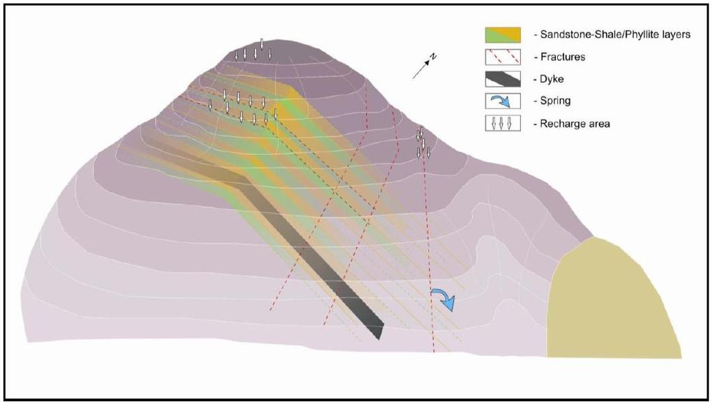
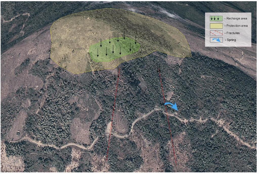
4 Springshed development: the process Hydrogeological mapping of springshed Classification of the spring Secondary data collection and interpretation Setting up a monitoring system for periodic spring discharge, rainfall and water quality data collection Identification of recharge area based on local geology and structure Delineation of the mountain aquifer Planning of treatment measures in the recharge area with the help of community participation Conceptual layout of spring
5 A Springshed plan Source development/construction Source protection -segregation for drinking, washing, cattle -source protection area (no open defecation, garbage disposal) Recharge -Trenches-Contour/staggered, recharge pits, Recharge shafts, Recharge wells (through rooftop rainwater harvesting), farm ponds, Farm bunds, farm slope Catchment area protection -protection of forest, protection from development, proper sanitation Discharge monitoring -monitoring setup Controlling soil erosion/velocity -plantation, check dams,

6 Watershed treatment Source: NREGA Watershed Works Manual, SPS, 2006
7 Process of Source Protection Protocols 1. Meeting with user group 2. Discussion of protection issues 3. Formation of user group 4. Awareness campaign with community & UG. 5. Training of User Group. 6. Discussion of protection for selected 7. Set Of Water Usage Regulation & Water Source Protection Protocol with the Help of community and UG. 8. Preparation Post Implementation O&M Plan. 9. Approval From Gram panchayat and Van Panchayat. 10. Formation of Gram Kosh by the User Group. 11. Formation of Yearly work plan by the user group with help of gram panchayat, van panchayat and other VLIs. 12. Evolution of Work plan by Gram Panchyat.

8 LOOSE BOULDER CHECKDAM It is a check dam made of stones in the path of a spring. Its depth is generally less than 3m. Its uses are: Retard the flow of water in the springs. Reduction in soil-erosion. Retard downstream fill up of ponds/dams with mud. Increase water table and perennial nature of springs
9 LOOSE BOULDER CHECKDAM Site selection: Easy availability of stones. Individual check dams should not have a catchment area of more than 1-2 hectare. Slope behind the check dam should be low as possible to accumulate maximum water. The banks of the stream should be strong enough. The banks should either have rock beddings or side foundations should be dug so as to reach the beddings. The area behind the check dam should have good permeability to facilitate percolation. This dam is generally made near the origin of springs. The vertical interval (VI) between 2 consecutive check dams should be equal to the height of the check dam. Horizontal interval (HI) is given by: This suggests that higher the slope of the stream closer the check dams should be made.
10 LOOSE BOULDER CHECKDAM Dimensions: Height generally varies between 80 cm to 150 cm. Width generally varies between 60 cm to 90 cm. Length generally varies between 3 m to 5 m. The length of the apron should be equal to the height of the check dam. The height of the weir should be around cm and its length is 1/3 rd of check dam length. The downstream side of the check dam should be made in a slope of 5:1 to 4:1. Bottom and side foundations should be given as and when required. Bottom foundations should be at least 25 cm in depth. Side foundations are generally 50 cm by 50
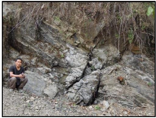
11 GULLY PLUG It is a small check dam made of stones in the pathway of a spring or gullies leading to the spring. Its uses are: Retard the flow of water in gullies to prevent their extension into springs. Reduction in soil erosion. Protect downstream structures like loose boulder check dams, Gabien and Sub surface check dams.
12 GULLY PLUG Site Selection Slope behind the check dam should be low to stop the impact of gushing water and to have some space for fill up of eroded soil/rocks. The banks of the stream should be strong enough. The banks should either have rock beddings or side foundation should be dug so as to reach them. Generally made in gullies leading to streams. Easy availability of stones. An important point to be kept in mind is that higher the slope of the gully closer the gully plugs should be made.

13 GULY PLUG Dimensions: Height of gully plugs extends to a maximum of m. Length of gully plugs extend to a maximum of 2 m. Width varies between m. Weir and apron are generally not given.
14 SUB SURFACE CHECKDAM Site Selection It stops the sub surface flow. This water can then be used to recharge the surrounding wells or guide the water into the adjacent formations to recharge downstream water sources. These dams are more advantageous in places having impermeable rock and clay. Its uses are: Retards the sub-surface water flow and recharge water sources. Increase perennial nature of water sources like wells, etc.
15 SUB SURFACE CHECKDAM recharge downstream water sources. These dams are more advantageous in places having impermeable rock and clay. Its uses are: Retards the sub-surface water flow and recharge water sources. Increase perennial nature of water sources like wells, etc. It stops the sub surface flow. This water can then be used to recharge the surrounding wells or guide the water into the adjacent formations to
16 GABIEN CHECKDAM The check dam is made with the help of steel wires and stones. Wires are woven into nets which enclose stones to form a rigid structure. Its uses are: Retard the flow of water in the springs. Reduction in soil-erosion. Retard downstream fill up of ponds/dams with mud. Increase water table and perennial nature of springs.
17 GABIEN CHECKDAM Site Selection: Individual check dams should not have a catchment area of more than 5 hectares. Easy availability of stones. Slope behind the check dam should be low as possible to accumulate maximum water. The banks of the stream should be strong enough. The banks should either have rock beddings or side foundations should be dug so as to reach the beddings. The area behind the check dam should have good permeability to facilitate percolation. Gabion check dams are generally made in the lower reaches of the spring.
18 BRUSH WOOD CHECKDAM It is a check dam made of stones and bamboo logs in the pathway of a spring. It is a permanent solution, cheap and requires least maintenance. It acts as a natural barrier after a couple of years. Its uses are: Retard the flow of water in the springs. Reduction in soil-erosion. Retard downstream fill up of ponds/dams with mud. Increase water table and perennial nature of springs.
19 BRUSH WOOD CHECKDAM Site selection: Easy availability of stones, logs (e.g. bamboo) and bushes having secondary regeneration. The logs and bushes should be alive and should sprout and grow. Individual check dams should not have a catchment area of more than 1 hectare. Slope behind the check dam should be low as possible to accumulate maximum water. Banks of the stream should be strong enough. The area behind the check dam should have good permeability to facilitate percolation. The area should have sufficient moisture to allow logs and bushes to sprout up. Sufficient soil depth is needed to plant the bamboo posts.
20 BRUSH WOOD CHECKDAM Construction/Dimensions: Prepare the wooden logs (or posts) according to height of the check dam keeping in mind that 1/3 rd of the height is underground. The height of brush wood check dam generally varies between 1-2 m. Length of the check dam generally varies between 4-5 m. The distance between consecutive bamboo posts in a single row is 2 ft and rows of such bamboo posts are constructed at a distance of 1 m from each other. The minimum number of rows is 2 and the number rarely exceeds 3. Fencing is done around the wooden posts to create pit type structures with jute or GI wires. The vacant space is than filled with bushes having lateral growth. Roughly 70% of the structural height is filled with bushes which are overlaid with stones to make the structure stable and rigid.
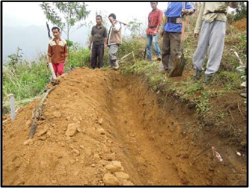
21 COUNTOUR TRENCH Long narrow pit dug on the contour line is called contour trench. The contour trench is at the same elevation from the sea level and thus water coming in it stops and settles. Its uses are: Retard the flow of water in the springs. Reduction in soil-erosion. Retard downstream fill up of ponds/dams with mud. Increase water table and perennial nature of springs. Increase moisture in the surrounding soil which can transform waste land into cultivable land. It also facilitates deposition of fertile soil in the respective area. Thus, contour trench construction should be associated with other activities like forestry.
22 COUNTOUR TRENCH Site Selection: Mountainous regions in Uttrakhand have high slope but one can find a lot of waste lands and abandoned terraces which are relatively flat. One should find the catchment/recharge area for a particular spring based on surface and sub-surface geology. Then such abandoned terraces and wastelands form perfect spots to dug contour trenches. Contour trenches are not dug if mud depth is very low and sub-surface has hard, rocky beds. Soil should be permeable and help in percolation of water down to water table.
23 COUNTOUR TRENCH Dimensions/Key Points: Consecutive contour trenches are dug 4-6 ft from each other. Contour trenches are generally dug at a cross-section of 1ft by 1ft. Mud excavated is spread on the downstream side at least 20 cm away from the contour trench. This distance is termed Berm and is necessary to prevent fall back of mud into the trench. The excavated mud is stabilized by pressing and growing grass/shrubs in it. Contour trenches are generally dug shorter than 4 m because its difficult to maintain the same contour along the entire length. Contour trenches in adjacent layers are dug / placed as shown in diagram to effectively trap all the water flowing down.

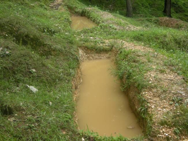
24 COUNTOUR TRENCH CONTOUR TRENCH
25 RECHARGE PONDS (KHAL) It is a large pit which catches surface run-off and facilitates water conservation and percolation. Its uses are: Retard the flow of water in the springs & reduction in soil-erosion. Retard downstream fill up of ponds/dams with mud. Increase water table and perennial nature of springs. Increase moisture in the surrounding soil which can transform waste land into cultivable land. Site Selection: Mountainous regions in Uttrakhand have high slope but one can find a lot of waste lands and abandoned terraces which are relatively flat. One should find the catchment/recharge area for a particular spring based on surface and sub-surface geology. Then such abandoned terraces and wastelands form perfect spots to dug Khals. Khals should be made where there is sufficient depth of soil. For instance, for constructing Khals of depth 1 m, the depth of soil should be a little over 1 m. Khals should be made over the rock strata which is permeable and has fractures/ sink holes, etc which can transport the percolated water to the spring we aim to recharge. Khals should be avoided where large
26 RECHARGE PONDS (KHAL) Dimensions: Length of Khal generally varies between 4 m to 10 m and Breadth of Khal generally varies between 2 m to 6 m. Depth of Khal generally varies between 1 to 1.5 m. Khals deeper than this are made in a step by step manner. E.g. 8m *2m*1m, 5m*2m*1m, etc.
27 RECHARGE PONDS (KHAL) Construction Parameters: The soil dug out can be handled in two ways. If it is fertile, it can be spread uniformly over contour terraces. Otherwise, it is spread on the downstream side of Khal and stabilized by growing grass and shrubs. Mud taken out is spread at least 1-2m away from the Khal. This distance is called Berm and prevents fall back of soil into the Khal. Long channels should be constructed to bring surface run-off from farther areas and thus increase catchment area of the Khal. The supporting channels should remain at same contour or slope otherwise they could easily become victims of soil erosion. A gap of 1 m should be left from terrace end otherwise Khal structure can make the whole terrace unstable.a deeper Khal is more favorable compared to a shallow Khal because of lower evaporation. Khal should be given proper exits to channelize overflow. We can also theoretically calculate the volume of Khal: V stands for volume of Khal. C stands for surface run-off coefficient. R stands for Maximum rainfall in a day. A stands for catchment area E stands for efficiency factor. f stands for number of times Khal is filled (generally 1.5 to 3).

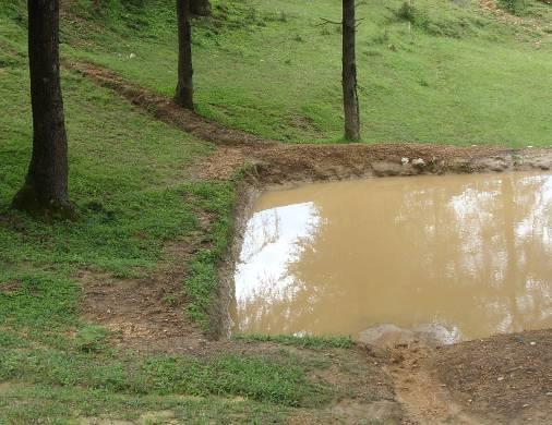
28 RECHARGE PONDS (KHAL)
29 PERCOLATION PIT It is a smaller version of Khal which catches surface runoff and facilitates water conservation and percolation. Its uses are: Retard the flow of water in the springs. Reduction in soil-erosion. Retard downstream fill up of ponds/dams with mud. Increase water table and perennial nature of springs. Increase moisture in the surrounding soil which can transform waste land into cultivable land. It also facilitates deposition of fertile soil in the respective area. Thus, contour trench construction should be associated with other activities like forestry. Site Selection: We should start with identifying the catchment area of the spring based on surface and sub surface geology. Percolation pits are characteristic of areas where the slope is very high and flat waste land and terraces are difficult to find. These are comparatively shorter pits and apt for hilly terrain like in uttrakhand. They are generally grown in numbers ranging from /hectare. Some points to be kept in mind are: Depth of soil must be at least cm. The bedrock/soil on which percolation pit is made must be permeable enough to facilitate quick percolation of water. Percolation Pits should be made over the rock strata which has fractures/ sink holes, etc which can transport the percolated water to the spring we aim to recharge

 varies between 1-3 ft.")
30 PERCOLATION PIT Dimensions: Length & Breadth generally varies between 1-3 ft each. Depth generally varies between 1-2 ft. Diameter (if made circular) varies between 1-3 ft. E.g. 1.5 ft by 1.5 ft by 1 ft.
31 TERRACE BUNDING/LEVELING Terrace bunding involves raising the boundary of the terrace to a contour higher than the general contour level of the terrace by using clay and other impermeable material. Leveling involves reducing the gap between highest and lowest contour levels in the terrace. Its uses are: Terrace bunding is done to prevent fertile soil erosion and maintain the much needed moisture in the terrace Retard downstream fill up of ponds/dams with mud. Increase water table and perennial nature of springs.
32 TERRACE BUNDING/LEVELING Site Selection: It is a collective activity which requires cooperation of entire farming community because partial bunding in terraces can be more harmful than profitable. It is done on fertile terraces in the catchment area where digging contour trenches and Khals can be objectionable Dimensions: Width generally varies from m (permeable soil) and m (impermeable soil). Height generally varies from m (permeable soil) and m (impermeable soil). Upstream / downstream slope generally varies between 3:1 to 5:1 for both soil types.
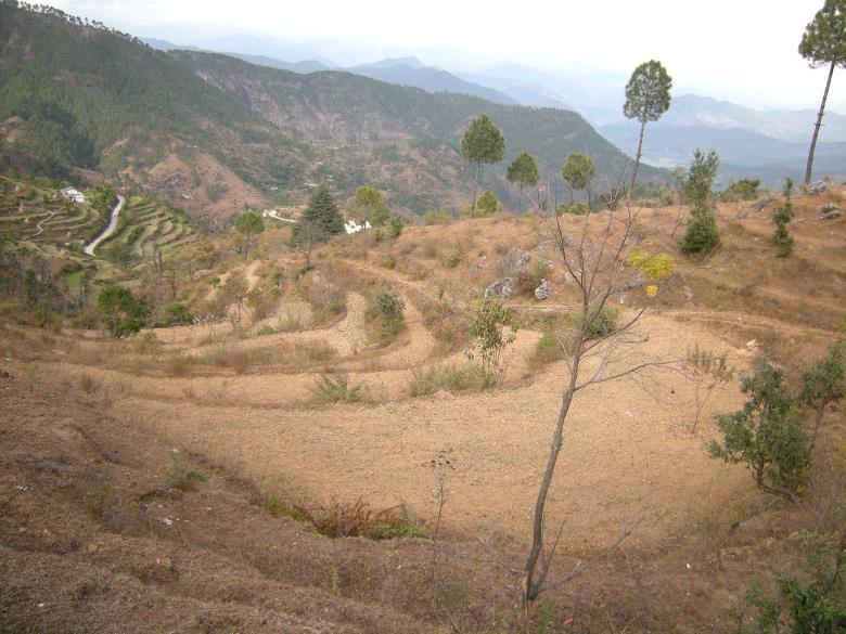

33 TERRACE BUNDING/LEVELING
34
35 Thanks