NDIA Test and Evaluation Conference
|
|
|
- Erick Fitzgerald
- 5 years ago
- Views:
Transcription
 and Modeling and")
 March 16, 2011 Larry Grello")
")
1 NDIA Test and Evaluation Conference Model Based Systems Engineering (MBSE) and Modeling and Simulation (M&S) adding value to Test and Evaluation (T&E) March 16, 2011 Larry Grello High Performance Technologies, inc Schrader Road Dover NJ, (973) ext 275, 1

2 Outline What was our Assignment The Approach to the Assignment Model Based Systems Engineering (MBSE) Systems Modeling (SysML) Pillars of SysML Capturing Requirements, Behavior, and Structure for our assignment Capturing Test Information Other Modeling Activities Planning Activities Lessons Learned
3 The Facility and the Assignment Hardware in the Loop (HIL) Facility Focus on testing of GPS-guided precision munitions Desiring a cost effective means for mitigating risks Capable of performing component and integrated component tests prior to gun launch testing Our Assignment Capture Stakeholder Requirements Capture System Requirements Capture Test and Evaluation information that the HIL Facility offers Traceability of Test and Evaluation information to the Requirements
4 How to capture the information for our assignment? Asked ourselves how to best accomplish our assignment Desire to capture Requirements, System Behaviors, and Test information in one location with traceability Desire to involve all stakeholders in the process and develop a common understanding early in the lifecycle Need to manage project risk Looked to a Model Based Systems Engineering Approach to help achieve this Focus on early developmental activities Scoping the system of interest Systems Engineering Approach 4


 Dynamic Simulation")

5 MBSE - General Definition It is about System Modeling System Model is a cohesive, unambiguous representation of what the System is and does. It provides a description of Requirements and Technical Solution and Operational Scenarios System Behavior (including I/O) Physical Architecture (Structure, interfaces) Dynamic Simulation (requires executable models) Verification Procedures MBSE is used to produce SE products It requires a Modeling Language that is computer interpretable Minimum Required to Define System


6 SysML Overview Descriptive Modeling General Purpose Visual Modeling Structure Behavior Requirements Parametric Supports: specification, analysis, design, verification and validation


7 4 Pillars of SysML 1. Structure 2. Behavior 3. Requirements 4. Parametrics 7

8 Capture Capabilities of the HIL Eliciting Threshold and Objective Capabilities Actors Use Cases (Goals) Used to review with team Helped to come up with stakeholder requirements and informally trace behavior to requirements Looked at HIL facility as a project
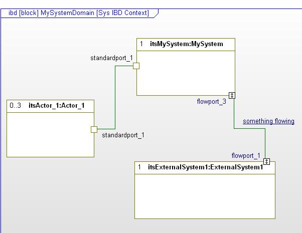
9 Capture Structure of the HIL Eliciting Structure of the HIL What is part of the system What is outside of system that interacts with our system Logical Abstraction of things that may end up being: Physical Equipment Software Information (e.g. documented procedures/enabling products)
10 Capture Behavior of the HIL Eliciting Behaviors of the HIL Could use Activity, Sequence, and/or State Diagrams Can look at from a domain perspective (which we did here) Here we elicit the actions for testing a weapon (which may or may not be tied to a specific capability)
11 Scope Behavior of the HIL Scope Behaviors of the HIL Used the activity diagrams to review actions of a test Next, it helped us decide what is part of the system and what is outside the system (i.e. allocation of behavior to structure in this case)


12 Capture Requirements of the HIL Capture Requirements of the HIL This was going on in parallel with capturing the capabilities, structure, and behavior Can be done within a modeling tool, requirements management tool, or both Relationships between the requirements and other model elements can be captured System Requirements in a requirements management tool >>>
.")
13 Capture Requirements of the HIL Capture Requirements of the HIL A trace view may be more appropriate and manageable for large projects than a diagram A trace view can be exported to a deliverable or format that can be used elsewhere (e.g. imported into a spreadsheet or requirements management tool). Some tools provide tables that would allow you to managed requirements within the MBSE tool (if desired).


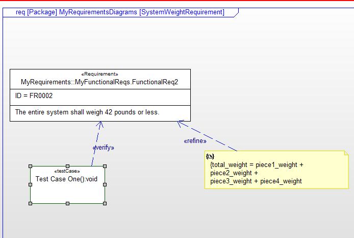
14 Capture Verification Information Capture Verification Information for the HIL Assignment was also to capture how the system requirements were going to be verified. MBSE can capture that information (e.g. relating verification to requirements). This can be captured and displayed in requirements diagrams, trace views, and behavior diagrams).
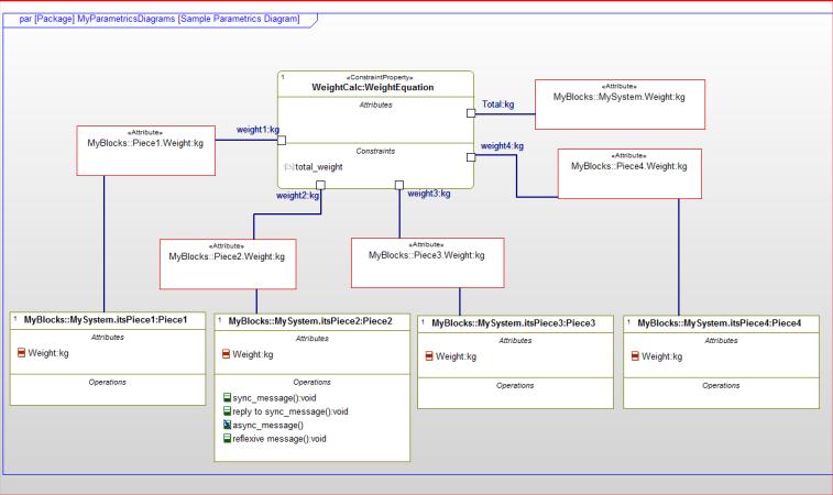
15 Capturing Parametrics Capturing equation data for your system of interest Interface with solvers to solve your equations Can create instances to look at different possible solutions (e.g. trade comparisons) Some examples of possible use: timeline analysis, failure analysis, reliability analysis, budgeting (e.g. weight, cost), aeroballistics model, optimize test set, model risk
16 Capturing Parametrics Simple example here is for a weight budget. The data for the equation is gathered in the block definition diagram. The wiring together of weight equation is done within a parametric diagram. The data can now be analyzed (which may mean interaction with a plug-in to the MBSE tool that serves a equation solver).
17 Capturing Parametrics For our HIL task assignment, we did some capturing of parametric data (informal). Interfaced with System Analysis team to explain the HIL testing related to the simulated projectile flight information. The diagrams to the right is a high level abstraction of that information (representative example).
18 Model Animation and Execution MBSE tools can be used to animate/execute behavior of your system of interest Executing an Activity Diagram Executing a State Machine Diagram Executing a Sequence Diagram Model animation can help with gap analysis Model animation identify interfaces within your system and domain Model animation can be used to prototype your system (or prototype different solutions/alternatives) An executable model provides the potential to auto-generate useful model artifacts 18
19 Planning Considerations Scoping the effort (and where modeling fits in for specific project) Need a MBSE process to follow (an approach) Common Modeling Language (e.g. SysML, UML) A Modeling Tool to capture the information Who is going to model the information (and be able to convey the information to the reviewers who aren t expected to be system modelers themselves) Who is going to review the information (impacts the scoping of the effort as well) 19
20 Conclusions/Lessons Learned Developed a common understanding of our system and what we needed to verify Assisted in defining and confirming: capabilities, requirements, structure, interfaces, and test information Formally documented the system and related verification information Didn t cause extra work (was part of the work; modeling assisted in delivering on schedule and quality work) Provided confidence to leadership that the project was meeting requirements and being verified 20