Work Study and Ergonomics
|
|
|
- Jocelin Jacobs
- 5 years ago
- Views:
Transcription
1 UNIT-I Work Study and Ergonomics Work Study Work Study is a generic term for management services and system engineering techniques, used to investigate: Methods of performing work (Method Study). The time taken to do it (Work Measurement). Method study is a technique to reduce the work content mainly by eliminating unnecessary movements by workers, materials, or equipments. However, even after that, there could be substantial unnecessary time taken for the process because of lack of management control or inaction of worker. Method Study approaches and tools of Method Analyst: Flow Diagrams & Process Charts etc. Critical questioning techniques. Method Study Objectives Improvement of processes and procedures. Improvement in the design of plant and equipment. Improvement of layout. Improvement in the use of men, materials and machines. Economy in human effort and reduction of unnecessary fatigue. Development of better working environment. Method study - Methodology Procedure to accomplish method study, called "SREDIM" shall be as follow: 1. Select: the job or operation that needs improvement, 2. Record: all facts, how work is done by chart methods, 3. Examine: every aspect of the job by asking; what, why, where, when, who and how 1

2 4. Develop: review ideas, eliminate, simplify, combine, re-arrange, make new method which more safe, chart new method, submit for approval, 5. Install: the new method, consider best time to introduce, convince all, train users, 6. Maintain: check frequently, match results, correct deviations. Method Study Tools Exploratory Tools Pareto Analysis Fish & Bone Diagrams Gantt and PERT charts Recording and Analysis Tools Operation Process Chart Flow process chart Flow diagram Worker and Machine Process Charts Gang Process charts Synchronous Servicing 2
3 The need for methods analysis can come from a number of different sources : Changes in tools and equipment. Changes in product design or new products. Changes in materials or procedures Other factors (e.g. accidents, quality problems) Recording Techniques Charts 1. Outline process chart. 2. Flow process chart (man-type, material-type and equipment-type): This is the use of symbols and description to chart the sequence of work. The process, then, show what is happening at different stages. The distances and time may be given. 3. Two hands process charts. 4. Multiple activity charts: This technique is used to solve problems where a number of items are dependent on each other. The aim is to reduce idle times by using the optimum number of each item. It depicts the occupied times-broken down into the number of different activities and the idle times both for the original and proposed methods of doing the job. Diagrams and models (2-D and/or 3-D) 1. Flow diagrams, which is the use of symbols for flow process charts, superimposed on drawings and the "descriptions" are not necessary. 2. String diagrams, which is used for solving movement problems since it shows congestions and excessive distances. 3. Cut-out templates (2-D models) D models. Photography 1. Photographs, 2. Films, 3. Video. 3
4 Assembly Chart It is an analog model of the assembly process. Circles with a single link denote basic components, circles with several links denote assembly operations/subassemblies, and squares represent inspection operations. The easiest method to constructing an assembly chart is to begin with the original product and to trace the product disassembly back to its basic components. Assembly Chart for producing Cheese Hamburger 4
5 Operation Process Chart The operation process chart shows the chronological sequence of all operations, inspections, time allowances, and materials used in a manufacturing or business process, from the arrival of raw material to the packaging of the finished product. The chart depicts the entrance of all components and subassemblies to the main assembly. Two symbols are used in constructing the operation process Chart : an operation and an inspection. Operations charts show the introduction of raw materials at the top of the chart on a horizontal line. Some parts require no fabrication steps. These parts are called buyouts. Buyouts are introduced above the operation Operations Chart Steps Step by Step Procedures For Preparing an Operations Chart: Identify the parts to be manufactured and purchased Determine the operations required to fabricate each part and sequence them Determine the sequence or assembly for buyouts and fabricated parts Draw the operations chart as explained Put time standards, operation numbers and descriptions Calculate and write down the total hours required per 1,000 units 5

6 Flow Diagrams A flow diagram is essentially a flow process chart drawn to: 1. Show the layout of a facility. 2. Show the flow of work through that area 3. Show overcrowding areas, crossing worker paths, total travel. 4. Identify how layout can be redesigned to reduce travel, motion, collisions, etc. 5. Store materials near where they are used. 6. Increase efficiency and safety. Usually, the objective is to look for spatial relationships. It depicts the probable movement of materials in the floor plant. The movement is represented by a line in the plant drawing. 6
7 Flow Process Charts A flow process chart is a chart of all the activities involved in a process. It is similar to an operations process chart, except that more detail is shown by including transportations and delays as well as operations, inspections, and storages. Not usually used for entire assemblies, it is used for just one component (or operator) Add in information on: Operation duration (time to complete) Distance traveled (for transport operations) Good for showing savings of a new method. Process charts summarizes the whole process They are used to compare the existing and the proposed methods Process is observed, who, what, where, when, and how questions are asked Every detail is understood and the chart of the existing situation is drawn Quantity: Operations: Pieces per hour Transportation: How many are moved at a time Inspection: How many pieces per hour if under time standard and/or frequency of inspection Delays: How many pieces in a container Storage: How many pieces per storage unit Time in Hours per Unit If 250 pieces are processed in an hour then 1 unit is processed in hours. Record 400 If 200 units are moved in 1 minute, then 1/200 = minutes per part, and 0.005/60 hours/part = hrs/part. Record 8. 7
8 Flow Process Types: Product or Material type Worker (Man) type Machine type 8

9 Flow Process Chart Symbols Occurs when an object is intentionally changed in one or more of its characteristics Usually occurs at a machine or a work station Drilling, Painting, Data Entry, Cutting, Sorting, etc. Occurs when an object is moved from one place to another except when the movement is part of an operation or an inspection Using elevator, carrying, moving with material handling devices Occurs when an object is examined for identification or is compared with a standard as to quantify or quality Examine the quantity or quality, read steam gauge on boiler, detect the defectives Occurs when the immediate performance or the next planned action does not take place Work In Process inventory waiting to be processed, Employee waiting for an elevator, Waiting for accumulation of a certain quantity for packaging Occurs when an object is kept under control such that its withdrawal requires authorization Bulk storage of raw material, finished products inventory, archived documents Combined Symbols Two symbols may be combined when two activities are performed concurrently. 9


10 Flow Process Chart-An Example Flow Process Chart Example 10

11 Material Type - Example 11

12 Left-Hand-Right-Hand Charts Useful in analyzing the work performed by one person at one specific workstation. As the name implies, the chart follows the motion of the left and right hands of one operator. Each hand of the worker is treated as an activity. Each hand s activities are broken into work elements and plotted side by side on a time scale. 12
13 Lists the work performed simultaneously by each hand Symbols To assist in finding a better method of performing the task and To train the operator in the preferred method. Two symbols are used in this chart: Transportation (either an arrow or a small circle) Action (e.g., grasp, position, use, release) A sketch of the workplace is drawn, indicating the contents of the bins and the location of tools and materials. Record the motions of one hand at a time Usually necessary to redraw the chart Left-Hand-Right-Hand Chart (An Example) 13

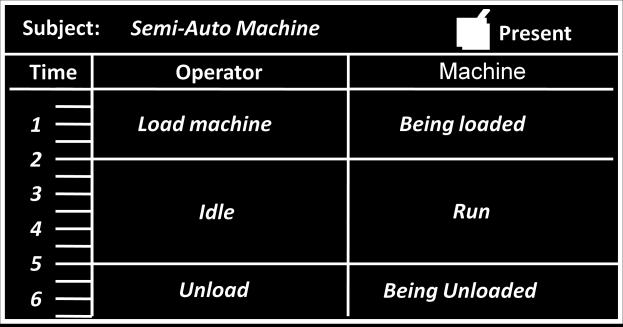
14 Man-machine chart The worker and machine process chart (Man-machine chart) is used to study, analyze, and improve one workstation at a time. The chart shows the exact time relationship between the working cycle of the person and operating cycle of the machine. These facts can lead to utilization of both worker and machine time, and a better balance of the work cycle. Worker-Machine Chart for a Gourmet Coffee Store 14

15 The customer, the clerk, and the coffee grinder (machine) are involved in this operation. It required 1 minute and 10 seconds for the customer to purchase a pound of coffee in this particular store. During this time the customer spent 22 seconds, or 31 percent of the time, giving the clerk his order, receiving the ground coffee, and paying the clerk for it. He was idle during the remaining 69 percent of the time. The clerk worked 49 seconds, or 70 percent of the time, and was idle 21 seconds, or 30 percent of the time. The coffee grinder was in operation 21 seconds, or 30 percent of the time, and was idle 70 percent of the time. Multiple Activity Charts Also known as Gang Process Charts Used when several workers operate a single machine or render a single service Used when a single worker is operating several machines Used to show the exact relationship between idle and operating times of both workers and machines An operation performed by one member of the group may continue while another member is performing more than one operation. The chart should cover the complete cycle for the longest performing member. 15

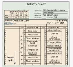
16 Activity Chart Activity Chart for Two-Person 16

17 Activity Chart of Emergency Tracheotomy Principles of Motion Economy As Related To The Use Of The Human Body 1. The two hands should begin as well as complete their motions at the same time. 2. The two hands should not be idle at the same time except during rest periods. 3. Motions of the arms should be made in opposite and symmetrical directions, and should be made simultaneously. 4. Hand and body motions should be confined to the lowest classification with which it is possible to perform the work satisfactorily. 17

18 5. Momentum should be employed to assist the worker whenever possible, and it should be reduced to a minimum if it must be overcome by muscular effort. 6. Smooth continuous curved motions of the hands are preferable to straight-line motions involving sudden and sharp changes in direction. 7. Ballistic movements are faster, easier, and more accurate than restricted (fixation) or controlled movements. 8. Work should be arranged to permit easy and natural rhythm wherever possible. 9. Eye fixations should be as few and as close together as possible. As Related To The Work Place 10.There should be a definite and fixed place for all tools and materials. 11.Tools, materials, and controls should be located close to the point of use. 18


19 16.The height of the work place and the chair should preferably be arranged so that alternate sitting and standing at work are easily possible. 19
20 As Related To The Design Of Tools And Equipment 18.The hands should be relieved of all work that can be done more advantageously by a jig, a fixture, or a foot-operated device. 19.Two or more tools should be combined wherever possible. 20.Tools and materials should be prpositioned whenever possible. 21.Where each finger performs some specific movement, such as in typewriting, the load should be distributed in accordance with the inherent capacities of the fingers. 22. Levers, hand wheels and other controls should be located in such positions that the operator can manipulate them with the least change in body position and with the greatest speed and ease. Introduction Work measurement Work measurement is the application of techniques designed to establish the time for a qualified worker to carry out specified jobs at a defined level of performance. We have seen how total time to manufacture a product is increased by: adding undesirable features to product, bad operation of the processes, and ineffective time added because of worker and management. All this leads to decreased productivity. Method study is one of principal techniques by which work content in the product manufacture or process could be decreased. It is a systematic method of investigating and critically examining the existing methods, to develop the improved ones. 20
21 Method study is, then, a technique to reduce the work content mainly by eliminating unnecessary movements by workers and/or materials and/or equipments. However, even after that, there could be substantial unnecessary time taken for the process because of lack of management control and/or inaction of worker. Work measurement (WM) is concerned with investigating, reducing and eliminating ineffective time, whatever may be the cause. WM is the means of measuring the time taken in the performance of an operation or series of operations in such a way that the ineffective time is shown up and can be separated out. In practice, proving existence of the ineffective time is the most difficult task. After existence is proved, nature and extent is easy to see! WM is also used to set standard times to carry out the work, so that any ineffective time is not included later. Any addition the standard time would show up as excess time and thus can be brought to attention. Since, standard times are set for all the activities through WM, it has earned bad reputation amongst workers. Major reason for that has been the initial focus of the WM methods, which essentially targeted only the worker controllable ineffective times. Management controllable ineffective times were ignored traditionally. Two critical issues in work study: 1. Method study should precede the work measurement, always. 2. Elimination of management controllable ineffective time should precede the elimination of the ineffective time within the control of the workers. 21
22 Purpose of WM To reveal the nature and extent of ineffective time, from whatever cause, So that action can be taken to eliminate it; and then, To set standards of performance that are attainable only if all avoidable ineffective time is eliminated and work is performed by the best method available. Uses of WM To compare the efficiency of alternative methods. Other conditions being equal, the method which takes the least time will be the best method. To balance the work of members of teams, in association with the multiple activity charts, so that, as far as possible, each member has tasks taking an equal time. To determine, in association with man and machine multiple activity charts, the number of machines an worker can run. Uses of time standards To provide information on which the planning and scheduling of production can be based, including the plant and labor requirements for carrying out the program of work and utilization of resources. To provide information on which estimates for tenders, selling prices and delivery promises can be based. To set standards of machine utilization and labor performance which can be used for incentive scheme. To provide information for labor-cost control and to enable standard costs to be fixed and maintained. 22
23 Stop watch time study Measuring Time with a Stop Watch There are two methods of timing using a stop watch. They are 1. Fly back or Snap back method. 2. Continuous or Cumulative method. 1. Fly back method Here the stop watch is started at the beginning of the first element. At the end of the element the reading is noted in the study sheet (in the WR column). At the same time, the stop watch hand is snapped back to zero. This is done by pressing down the knob, immediately the knob is released. The hand starts moving from zero for timing the next element. In this way the timing for each element is found out. This is called observed time (O.T.). Factors affecting rate of working Factors within worker s control: Acceptable variation in the quality of the process/product. Variation due to worker s ability. Variation due to ability of mind, specifically attitude. Optimum pace at which the worker will work depends on The physical effort demanded by the work. The care required on the part of the worker. Training and experience. Rating factor The figure 100 represents standard performance. 23
24 If the operator is apparently performing with less effective speed, than the assigned factor is less than 100. If, on the other hand, the effective rate of working is above standard, the operator gets a factor above hundred. Essential idea being: Observed time x Rating = Constant This constant is known as the basic time: Rating So, depending on the rating assigned for the operator, the basic time can either be less than or greater than the observed time. Selected time Observed time The selected time is the time chosen as being representative of a group of times for which an element or group of elements. These times may be either observed or basic times; and should be denoted as selected observed or selected basic times. Theoretically, the results of all the computations of the basic time for any single constant element should be same. However, because of inherent process variations, it happens rarely! It becomes necessary to select a representative time for each element from all the basic times which have been entered into the time study. Multiple ways to pick a representative selected time from the available ones. Statistics suggests.. Taking averages! x Rating Standard There are other ways though! Basic Time Before the selected time is decided, the anomalies in the sample should be noted. Exceptionally high or low points should get some attention. 24
25 Constant element A very high or short observed time for a given element of job should be treated with caution. An exceptionally high observed time could be due to incorrect recording, but most common reason is material or environment variation. In such as case, it should be checked whether such a variation is frequent or rare. Excess observed time because of rarely occurring events is typically not included as a representative. The average time calculations should exclude this observation. But, the excess-overaverage time is added to the contingency allowance. Frequent large variations indicate that the element is not a constant one but a variable element. Excessively large time for this element could be detected by corresponding reduction in time for the immediate element. Exceptionally short times could be due to human error. A rare reason of observation of such short times could also be a last-minute-processimprovement. In such as case, the job should be studied again with more detailed attention. Variable element In general more observations will be necessary of a variable element than of a constant element before reliable representative basic times can be established. The analysis of factors affecting the time to complete the element should be closely studied. Some relationship should be established between the observed time and the variable factors. Multiple factors could be affecting the observed time variation and establishing relationships amongst multiple factors is difficult 25
26 Work content The work content of a job or operation is defined as: basic time+ relaxation allowance+ any allowance for additional work (e.g. the part of relaxation allowance that is work related). Standard time is the total time in which a job should be completed at standard performance i.e. work content, contingency allowance for delay, unoccupied time and interference allowance. Allowance for unoccupied time and interference may not be frequently included in the standard time calculations; however, the relaxation allowance is. Standard time constituents A contingency allowance is a small allowance of time which may be included in a standard time to meet legitimate and expected items of work or delays, precise measurement of which is uneconomical because of their infrequent or irregular occurrence. Contingency allowance for work should include fatigue allowance; whereas the allowance for delay should be dependent on the workers. Typically contingency allowances are very small and are generally expressed as percentage of the total repetitive minutes of the job. Contingency allowance should not be more than 5%, and should only be given where the contingencies cannot be eliminated and are justified. Relaxation allowance is an addition to the basic time intended to provide the worker with the opportunity to recover from the physiological and psychological effects of carrying out specified work under specified conditions and to allow attention to personal needs. The amount of the allowance will depend on the nature of the job. One of the major additions to the basic time. Industrial fatigue allowance, in turn, forms a major portion of the relaxation allowance. Relaxation allowances are also given as percentages of the basic times. 26
27 Typical values of relaxation allowance are 12-20%. In addition to including relaxation allowances, short rest pauses could be added over the period of work for an operator. Other allowances Start-up / shut-down allowance Cleaning allowance Tooling allowance Set-up / change-over allowance Reject / excess production allowance Learning / training allowance Policy allowance is an increment, other than the bonus increment, applied to standard time to provide a satisfactory level of earning for certain level of performances under exceptional conditions. Standard time Now, we can add all the constituents to arrive at the standard time for a job. Standard time = observed time + rating factor + relaxation allowance + work related contingency allowance + delay related contingency allowance. ERGONOMICS Ergons means work and Nomos means Natural laws. Ergonomics or its American equivalent Human Engineering may be defined as the scientific study of the relationship between man and his working environments. Ergonomics implies Fitting the job to the worker. Ergonomics combines the knowledge of a psychologist, physiologist, anatomist, engineer, anthropologist and a biometrician. Objectives 27
28 The objectives of the study of ergonomics is to optimize the integration of man and machine inorder to increase work rate and accuracy. It involves The design of a work place befitting the needs and requirements of the worker. The design of equipment, machinery and controls in such a manner so as to minimize mental and physical strain on the worker thereby increasing the efficiency, and The design of a conductive environment for executing the task most effectively. Both work study and Ergonomics are complementary and try to fit the job to the workers; however Ergonomics adequately takes care of factors governing physical and mental strains. Applications In practice, ergonomics has been applied to a number of areas as discussed below 1. Working environments 2. The work place and 3. Other areas. 1. Working environments (a) The environment aspect includes considerations regarding light, climatic conditions (i.e., temperature, humidity and fresh air circulation), noise, bad odour, smokes, fumes, etc., which affect the health and efficiency of a worker. work. (b) Day light should be reinforced with artificial lights, depending upon the nature of (c) The environment should be well-ventilated and comfortable. (d) Dust and fume collectors should preferably be attached with the equipments giving rise to them. 2. Work place layout Design considerations (a) Materials and tools should be available at their predetermined places and close to the worker. used. (b) Tools and materials should preferably be located in the order in which they will be 28
29 (c) The supply of materials or parts, if similar work is to be done by each hand, should be duplicated. That is materials or parts to be assembled by right hand should be kept on right hand side and those to be assembled by the left hand should be kept on left hand side. (d) Gravity should be employed, wherever possible, to make raw materials reach the operator and to deliver material at its destination (e.g., dropping material through a chute). (e) Height of the chair and work bench should be arranged in a way that permits comfortable work posture. 29