By choosing to view this document, you agree to all provisions of the copyright laws protecting it.
|
|
|
- Edmund Collins
- 5 years ago
- Views:
Transcription
1 Copyright 2015 IEEE. Reprinted, with permission, from Carl S. Carlson, Understanding and Applying the Fundamentals of FMEAs, 2015 Reliability and Maintainability Symposium, January, This material is posted here with permission of the IEEE. Such permission of the IEEE does not in any way imply IEEE endorsement of any of ReliaSoft Corporation's products or services. Internal or personal use of this material is permitted. However, permission to reprint/republish this material for advertising or promotional purposes or for creating new collective works for resale or redistribution must be obtained from the IEEE by writing to By choosing to view this document, you agree to all provisions of the copyright laws protecting it.
2 2015 Annual RELIABILITY and MAINTAINABILITY Symposium Understanding and Applying the Fundamentals of FMEAs Carl S. Carlson Carl S. Carlson ReliaSoft Corporation 1450 S. Eastside Loop Tucson, Arizona USA Tutorial Notes 2015 AR&MS
3 SUMMARY & PURPOSE Across the globe, development times are becoming shorter, cost concerns more acute, and customers are demanding and expecting absolute safety and high reliability. While it may have been sufficient in the past to focus on testing and analysis as the primary methods for ensuring high reliability, this is no longer sufficient. The focus needs to be on problem prevention, anticipating the factors that lead to failure and ensuring designs are robust. Failure Mode and Effects Analysis (FMEA) can anticipate and prevent problems, reduce costs, shorten product development times, and achieve safe and highly reliable products and processes. The plain truth is FMEA has the potential to be a very powerful tool to achieve high reliability in products and processes; and when done well, it is remarkably effective. Yet in practice, FMEA does not always achieve the expected results. It has to be done correctly: performed on the correct parts, by the correct team, during the correct timeframe, with the correct procedure. The purpose of this tutorial is to share the fundamental concepts and procedures for effective FMEAs and highlight the FMEA success factors. Carl S. Carlson Carl S. Carlson is a consultant and instructor in the areas of FMEA, reliability program planning and other reliability engineering disciplines. He has 30 years of experience in reliability testing, engineering, and management positions, and is currently supporting clients of ReliaSoft Corporation with reliability and FMEA training and consulting. Previous to ReliaSoft, he worked at General Motors, most recently as senior manager for the Advanced Reliability Group. His responsibilities included FMEAs for North American operations, developing and implementing advanced reliability methods, and managing teams of reliability engineers. Previous to General Motors, he worked as a Research and Development Engineer for Litton Systems, Inertial Navigation Division. Mr. Carlson co-chaired the cross-industry team that developed the commercial FMEA standard (SAE J1739, 2002 version), participated in the development of SAE JA 1000/1 Reliability Program Standard Implementation Guide, served for five years as Vice Chair for the SAE's G-11 Reliability Division, and was a four-year member of the Reliability and Maintainability Symposium (RAMS) Advisory Board. He holds a B.S. in Mechanical Engineering from the University of Michigan and completed the 2-course Reliability Engineering sequence from the University of Maryland's Masters in Reliability Engineering program. In 2007, he received the Alan O. Plait Award for Tutorial Excellence. He is a Senior Member of ASQ and a Certified Reliability Engineer. His book, Effective FMEAs, was published in 2012 by John Wiley & Sons. Table of Contents 1. Introduction Understanding the fundamentals and procedures of FMEAs Selecting the right FMEA projects Preparation steps for each FMEA project Applying lessons learned and quality objectives Providing excellent facilitation Implementing an effective company-wide FMEA process Conclusions References Appendix - Problems and Solutions Tutorial Visuals ii Carlson 2015 AR&MS Tutorial Notes
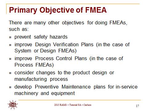
4 1.1 Brief history of FMEA 1. INTRODUCTION FMEA was formalized in 1949 by the US Armed Forces by the introduction of Mil-P 1629 Procedure for performing a failure mode effect and criticality analysis.. The objective was to classify failures according to their impact on mission success and personnel/equipment safety. [1] It was later adopted in the Apollo space program to mitigate risk due to small sample sizes. The use of FMEA gained momentum during the 1960s, with the push to put a man on the moon and return him safely to earth. In the late 1970s the Ford Motor Company introduced FMEA to the automotive industry for safety and regulatory consideration after the Pinto affair. They also used it to improve production and design. In the 1980s, the automotive industry began implementing FMEA by standardizing the structure and methods through the Automotive Industry Action Group. Although developed by the military, the FMEA method is now extensively used in a variety of industries including semiconductor processing, foodservice, plastics, software, aeronautics, automotive, and healthcare, to name a few. [2] 1.2 FMEA Standards There are many standards and guidelines published that cover the scope and general procedure for doing FMEAs or FMECAs. Some of the more common and relevant are: SAE J1739, Potential Failure Mode and Effects Analysis in Design (Design FMEA), Potential Failure Mode and Effects Analysis in Manufacturing and Assembly Processes (Process FMEA) [2009] AIAG, Potential Failure Mode and Effects Analysis (FMEA) Reference Manual Fourth Edition [2008] MIL-STD-1629A, Procedures for Performing a Failure Mode Effects and Criticality Analysis (Cited for cancelation in 1994, but still used in some military and other applications) SAE ARP5580, Recommended Failure Modes and Effects Analysis (FMEA) Practices for Non-Automobile Applications [2001] IEC 60812, Analysis techniques for system reliability Procedure for failure mode and effects analysis (FMEA) [2006] 1.3 Why do FMEAs? There are a number of business reasons to implement an effective FMEA Process. When done well, FMEA is a proven tool to reduce life cycle warranty costs. When done well, FMEAs will reduce the number of oops during product development. It is far less expensive to prevent problems early in product development than fix problems after launch. FMEAs can identify and address safety issues before a potential catastrophe. 1.4 Definition and purpose of FMEA Failure Mode and Effects Analysis is a method designed to: Identify and fully understand potential failure modes and their causes, and the effects of failure on the system or end users, for a given product or process. Assess the risk associated with the identified failure modes, effects and causes, and prioritize issues for corrective action. Identify and carry out corrective actions to address the most serious concerns. An FMEA is an engineering analysis done by a crossfunctional team of subject matter experts that thoroughly analyzes product designs or manufacturing processes, early in the product development process. Its objective is finding and correcting weaknesses before the product gets into the hands of the customer. [3] An FMEA should be the guide to the development of a complete set of actions that will reduce risk associated with the system, subsystem, and component or manufacturing/assembly process to an acceptable level. [3] Performing an FMEA just to fill a checkbox in the Product Development Process and then filing it away, never to be seen again, is a waste of time and adds no value. If not for use as guidance through the development process, why waste the time and resources to do it in the first place? If effectively used throughout the product life cycle, it will result in significant improvements to reliability, safety, quality, delivery, and cost. [3] The primary objective of an FMEA is to improve the design. For System FMEAs, the objective is to improve the design of the system. For Design FMEAs, the objective is to improve the design of the subsystem or component. For Process FMEAs, the objective is to improve the design of the manufacturing process. [3] There are many other objectives for doing FMEAs, such as: [3] identify and prevent safety hazards minimize loss of product performance or performance degradation improve test and verification plans (in the case of System or Design FMEAs) improve Process Control Plans (in the case of Process FMEAs) consider changes to the product design or manufacturing process identify significant product or process characteristics develop Preventive Maintenance plans for in-service machinery and equipment develop online diagnostic techniques 1.5 Types of FMEAs The most common types of FMEAs are System FMEA, Design FMEA and Process FMEA. System FMEA is the highest-level analysis of an entire system, made up of various subsystems. The focus is on system-related deficiencies, including system safety, system integration, interfaces or interactions between subsystems or 2015 Annual RELIABILITY and MAINTAINABILITY Symposium Carlson 1
.")
5 with other systems, interactions with the surrounding environment, human interaction, service, and other issues that could cause the overall system not to work as intended. In System FMEAs, the focus is on functions and relationships that are unique to the system as a whole (i.e., do not exist at lower levels). Included are failure modes associated with interfaces and interactions, in addition to considering singlepoint failures (where a single component failure can result in complete failure of the entire system). Some practitioners separate out human interaction and service into their own respective FMEAs. Design FMEA focuses on product design, typically at the subsystem or component level. The focus is on design-related deficiencies, with emphasis on improving the design and ensuring product operation is safe and reliable during the useful life of the equipment. The scope of the Design FMEA includes the subsystem or component itself, as well as the interfaces between adjacent components. Design FMEA usually assumes the product will be manufactured according to specifications. Process FMEA focuses on the manufacturing or assembly process, emphasizing how the manufacturing process can be improved to ensure that a product is built to design requirements in a safe manner, with minimal downtime, scrap and rework. The scope of a Process FMEA can include manufacturing and assembly operations, shipping, incoming parts, transporting of materials, storage, conveyors, tool maintenance, and labeling. Process FMEAs most often assume the design is sound. Failure Mode Effects and Criticality Analysis (FMECA) is similar to FMEA, with the added step of a more formal Criticality Analysis. This added step commonly requires objective data to support the criticality calculation. It is recommended for practitioners who are required to perform a FMECA analysis to understand the basics of FMEA first, and then to learn the FMECA procedure. Some other types of FMEAs include Concept FMEA, a short version of FMEA to aid in selecting optimum concept alternatives or to determine changes to system design specifications; Maintenance FMEA, in support of Reliability Centered Maintenance projects; Hazard Analysis, which focuses on identifying and addressing potential hazards associated with the use of a product; and Software FMEA, which identifies system weaknesses, and evaluates the effectiveness of the software architecture and software specifications. 1.6 FMEA Success Factors There are six broad success factors that are critical to uniformity of success in the application of FMEA in any company. The six success factors are listed here, and will be elaborated on later in this tutorial. 1. Understanding the fundamentals and procedures of FMEAs, including the concepts and definitions. 2. Selecting the right FMEA projects 3. Preparation steps for each FMEA project 4. Applying lessons learned and quality objectives 5. Providing excellent facilitation 6. Implementing an effective company-wide FMEA process. Implementing these FMEA success factors will help ensure FMEAs achieve safe, reliable and economical products and processes. 2. UNDERSTANDING THE FUNDAMENTALS AND PROCEDURES OF FMEAS It is important to begin with an understanding of the basic definitions of FMEAs. Time spent toward understanding the fundamental concepts and definitions of FMEAs will shorten the time in meetings and help ensure high quality results. There is no substitute for having a thorough knowledge and understanding of the FMEA definitions and concepts. Figure 1 is an example of a Generic FMEA Worksheet, truncated after the Recommended Actions column. The numbers in the illustration correspond to the subsections in this paper. The definitions are presented in the sequence they are normally developed in an FMEA project. 2.1 Item Figure 1. Generic FMEA Worksheet, up through Recommended Actions An item (1) is the focus of the FMEA project. For a System FMEA this is the system itself. For a Design FMEA, this is the subsystem or component under analysis. For a Process FMEA, this is usually one of the specific steps of the manufacturing or assembly process under analysis, as represented by an operation description. Figure 2 is an example of an Item for a Design FMEA. Figure 3 is an example of an Item for a Process FMEA. Figure 2. Example of an Item for Design FMEA [3] 2 Carlson 2015 AR&MS Tutorial Notes


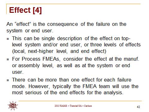
6 Dictionary defines the word failure as the act of ceasing to function or the state of not functioning. Mode is defined as a way in which something occurs. Figure 6 is an example of a Failure Mode for a Design FMEA. Figure 7 is an example of a Failure Mode for a Process FMEA. Figure 3. Example of an Item for a Process FMEA [3] 2.2 Function A function (2) is what the item or process is intended to do, usually to a given standard of performance or requirement. For Design FMEAs, this is the primary purpose or design intent of the item. For Process FMEAs, this is the primary purpose of the manufacturing or assembly operation. Functions are typically described in a verb-noun format. It is essential to include the standard of performance as part of the function statement in order to help describe the failure mode. There can be many functions for each item or operation. Figure 4 is an example of example of a Function for a Design FMEA [3]. Figure 5 is an example of a Function for a Process FMEA. Note, in the case of Process FMEAs, the function can be similar to the item, as described in the operation description for the manufacturing or assembly process. Figure 5. Example of a Function for Process FMEA [3] Figure 6. Example of a Failure Mode for Design FMEA [3] Figure 4. Example of a Function for a Design FMEA [3] 2.3 Failure Mode A failure mode (3) is the manner in which the item or operation potentially fails to meet or deliver the intended function and associated requirements. It may include failure to perform a function within defined limits, inadequate or poor performance of the function, intermittent performance of a function, and/or performing an unintended or undesired function. The term failure mode combines two words that both have unique meanings. The Concise Oxford English Figure 7. Example of Failure Mode for Process FMEA [3] 2.4 Effect An effect (4) is the consequence of the failure on the system or end user. This can be a single description of the effect on the top-level system and/or end user, or three levels of effects (local, next-higher level, and end effect). For Process FMEAs, consider the effect at the manufacturing or assembly level, as well as at the system or end user. There can be more than one effect for each failure mode. However, typically the FMEA team will use the most serious of the end effects for the 2015 Annual RELIABILITY and MAINTAINABILITY Symposium Carlson 3
 is a ranking number associated with the most serious effect for a given failure mode, based on the criteria from a severity scale.")


![Example of a Severity scale for Process FMEAs [4] Figure 9. Example of an Effect for a Process FMEA [3] 2.](/docs-images/89/98073121/images/7-3.jpg "6 Cause A cause (6) is the specific reason for the failure, preferably found by asking why until the root cause is determined.")

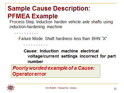
7 analysis. Figure 8 is an example of an Effect for a Design FMEA. Figure 9 is an example of an Effect for a Process FMEA. 2.5 Severity Severity (5) is a ranking number associated with the most serious effect for a given failure mode, based on the criteria from a severity scale. It is a relative ranking within the scope of the specific FMEA determined without regard to the likelihood of occurrence or detection. Figure 10 is an example of a Severity scale for Design FMEAs. Figure 11 is an example of a Severity scale for Process FMEAs. Note, when applying the severity scale for Process FMEAs, the team assesses the severity of the effect on both product and process and uses the worst case. Cause for a Process FMEA. Figure 10.Example of a Severity scale for Design FMEAs [4] Figure 8. Example of an Effect for a Design FMEA [3] Figure 11. Example of a Severity scale for Process FMEAs [4] Figure 9. Example of an Effect for a Process FMEA [3] 2.6 Cause A cause (6) is the specific reason for the failure, preferably found by asking why until the root cause is determined. For Design FMEAs, the cause is the design deficiency that results in the failure mode. For Process FMEAs, the cause is the manufacturing or assembly deficiency that results in the failure mode. At the component level, cause should be taken to the level of failure mechanism. If a cause occurs, the corresponding failure mode occurs. There can be many causes for each failure mode. Figure12 is an example of a Cause for a Design FMEA. Figure 13 is an example of a Figure 12. Example of a Cause for a Process FMEA [3] 4 Carlson 2015 AR&MS Tutorial Notes
![development, or actions to detect a problem during service before it becomes catastrophic. There can be many controls for each cause. Figure 13. Example of a Cause for a Process FMEA [3] 2.](/docs-images/89/98073121/images/8-0.jpg "7 Occurrence Occurrence (7) is a ranking number associated with the likelihood that the failure mode and its associated cause will be present in the item being analyzed.")

8 development, or actions to detect a problem during service before it becomes catastrophic. There can be many controls for each cause. Figure 13. Example of a Cause for a Process FMEA [3] 2.7 Occurrence Occurrence (7) is a ranking number associated with the likelihood that the failure mode and its associated cause will be present in the item being analyzed. For System and Design FMEAs, consider the likelihood of occurrence during the design life of the product. For Process FMEAs consider the likelihood of occurrence during production. It is based on the criteria from the corresponding occurrence scale, and has a relative meaning rather than absolute value, determined without regard to the severity or likelihood of detection. Figure 14 is an example of an Occurrence scale for Design FMEAs. Figure 15 is an example of an Occurrence scale for Process FMEAs. Figure 14. Example of an Occurrence scale for Design FMEAs [4] 2.8 Controls Controls (8) are the methods or actions currently planned, or already in place, to reduce or eliminate the risk associated with each potential cause. Controls can be the methods to prevent or detect the cause during product Figure 15. Example of an Occurrence scale for Process FMEAs [4] For System or Design FMEAs, prevention-type design controls describe how a cause, failure mode, or effect in the product design is prevented based on current or planned actions. They are intended to reduce the likelihood that the problem will occur, and are used as input to the occurrence ranking. Only those prevention-type controls that are currently planned, or are already in place, should be entered onto the FMEA worksheet. Detection-type design controls describe how a failure mode or cause in the product design is detected, based on current or planned actions before the product design is released to production, and are used as input to the detection ranking. They are intended to increase the likelihood that the problem will be detected before it reaches the end user. Only those detection-type controls that are currently planned, or are already in place, should be entered onto the FMEA worksheet. [3] Figure 16 is an example of Design Controls for a Design FMEA. For Process FMEAs, prevention-type process controls describe how a cause, failure mode or effect in the manufacturing or assembly process is prevented, based on current or planned actions. Detection-type process controls describe how a failure mode or cause in the manufacturing or assembly process is detected, based on current or planned action, before the item is shipped from the manufacturing or assembly plant, and are used as an input to the detection ranking. [3] Figure 17 is an example of Process Controls for a Process FMEA Annual RELIABILITY and MAINTAINABILITY Symposium Carlson 5
![Figure 16. Example of Design Controls for a Design FMEA: [3] Figure 18. Example of Detection scale for Design FMEAs [4] Figure 17. Example of Process Controls for a Process FMEA [3] 2.](/docs-images/89/98073121/images/9-0.jpg "9 Detection Detection (9) is a ranking number associated with the best control from the list of detection-type controls, based on the criteria from the detection scale.")


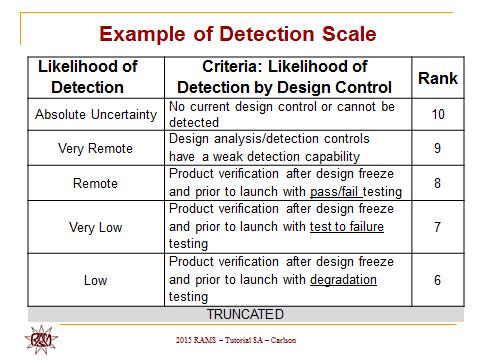
9 Figure 16. Example of Design Controls for a Design FMEA: [3] Figure 18. Example of Detection scale for Design FMEAs [4] Figure 17. Example of Process Controls for a Process FMEA [3] 2.9 Detection Detection (9) is a ranking number associated with the best control from the list of detection-type controls, based on the criteria from the detection scale. It considers the likelihood of detection of the failure mode/cause, according to defined criteria. It is a relative ranking within the scope of the specific FMEA, and is determined without regard to the severity or likelihood of occurrence. Figure 18 is an example of a Detection scale for Design FMEAs. Figure 19 is an example of a Detection scale for Process FMEAs. Caution is advised when using a Detection scale. The examples in figures 18 and 19 attempt to integrate three types of detection risk into one scale: risk due to the likelihood that the detection-type controls will detect the cause of the failure, risk due to the timing of the detection-type controls, and risk due to the type of detection controls. Practitioners need to be aware of the criteria inherent in detection scales and ensure they are properly used Risk Priority Number (RPN) RPN (10) is a numerical ranking of the risk of each potential failure mode/cause, made up of the arithmetic product of the three elements: severity of the effect, likelihood of occurrence of the cause, and likelihood of detection of the cause. Figure 19. Example of a Detection scale for Process FMEAs [4] Example: If the effect of a failure mode has a severity ranking of 10, and the cause of the failure mode has an occurrence ranking of 6 and detection ranking of 4, then the RPN will be 240 (severity 10 x occurrence 6 x detection 4) RPN Limitations RPN has a number of limitations and is not a perfect representation of the risk associated with a failure mode and associated cause. Practitioners who use RPN should be aware of the inherent limitations and take measures to be sure product and process risks are properly characterized and addressed. Examples of limitations to RPN include: 1. It is subjective, not objective 2. The potential values of RPN are not continuous 3. The Detection scale has its own limitations 4. There are many duplicate RPN values, representing different combinations of severity, occurrence and detection rankings 5. The practice of using RPN thresholds is not advised. 6 Carlson 2015 AR&MS Tutorial Notes
 uses severity and occurrence risk rankings as input to the criticality risk, without the use of a detection risk ranking.")


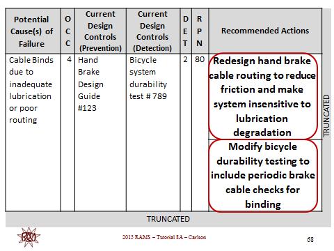
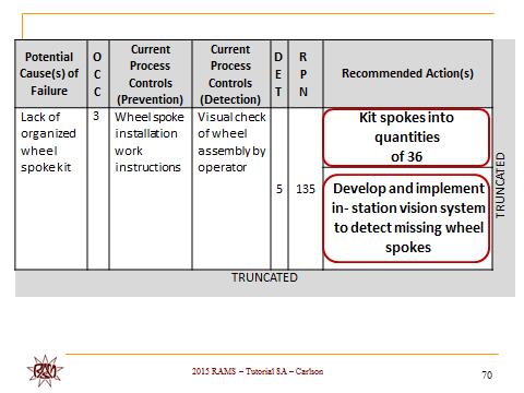
10 When RPN is used high severity must be considered regardless of RPN value. Many companies use alternatives to RPN, such as severity and occurrence. For example, FMECA (FMEA, with the added step of Criticality Analysis) uses severity and occurrence risk rankings as input to the criticality risk, without the use of a detection risk ranking. When severity and occurrence risk rankings are used by themselves, care must be taken to understand potential risk due to inability to detect failure modes and their causes, and properly characterize and address this risk Use of Risk-Ranking Scales If the risk-ranking scales are not mandated and the team has the flexibility to establish their own scales, the riskranking criteria can be tailored, along with the worksheet columns, to satisfy company-specific applications. Regarding the number of scale ranking levels, there is a simple rule to follow: use the minimum number of ranking levels for each scale that adequately differentiates the risk criteria. In other words, if the team can manage with five ranking levels and the needed differentiation of risk for a given application is adequately defined, then use ranking scales with five levels. If ten ranking levels are needed to adequately differentiate and define the risk, use scales that have ten ranking levels Recommended Actions Recommended actions (11) are the tasks recommended by the FMEA team to reduce or eliminate the risk associated with potential causes of failure. They should consider existing controls, relative importance (prioritization) of the issue, and the cost and effectiveness of the corrective action. There can be many recommended actions for each cause. In practice, it usually takes more than one, and sometimes many actions to address high risk issues. The FMEA team must adequately address all highseverity as well as high-rpn issues. Every task the FMEA team recommends (that is different from what is already planned or in place) shows up in the Recommended Actions column. Figure 20 is an example of Recommended Actions for a Design FMEA. Figure 21 is an example of Recommended Actions for a Process FMEA. Completing the FMEA worksheet, Actions Taken is the specific action that is implemented to reduce risk to an acceptable level. It should correlate to the specific recommended action, and is assessed as to effectiveness by a revised severity, occurrence, detection ranking, and corresponding revised RPN. Figure 22 shows the logical relationship between the various elements of FMEAs. Figure 20. Example of Recommended Actions for a Design FMEA [3] Figure 21. Example of Recommended Actions for a Process FMEA [3] Figure 22. The Logical Relationship Between FMEA Elements [3] 3. SELECTING THE RIGHT FMEA PROJECTS FMEAs take time and cost money. They should be done when a certain level of risk can be effectively addressed by the FMEA procedure. New product designs can include hundreds or even thousands of subsystems and components. Few companies have the resources to properly do FMEAs on everything. New or modified designs usually require a System FMEA. Lower level FMEA projects can be identified based on well-defined selection criteria. Companies can identify important criteria for selecting FMEA projects Annual RELIABILITY and MAINTAINABILITY Symposium Carlson 7


11 Selection criteria may include: New technology New designs where risk is a concern New applications of existing technology Potential for safety issues History of significant field problems Potential for important regulation issues Mission Critical applications Supplier Capability The risk criteria can each be assessed on a variable scale for the items being considered for FMEAs. Preliminary Risk Assessment criteria can be tailored to the unique needs of any company. Figure 23 shows an example of preliminary risk assessment done on a bicycle system. This example only shows the bicycle subsystems. The same process can be applied to all of the bicycle components to select FMEA projects. Figure 23. Preliminary Risk Assessment on Bicycle Subsystems [3] 3.1 Timing criteria for FMEAs In general, FMEAs should be done early in the product development process, where design and process changes can be most easily implemented. Concept FMEAs should be performed during the time when concept alternatives are being considered and before design or process concepts have been selected. System FMEA should be started as soon as the system configuration is determined and completed before the system configuration freeze-date. Design FMEAs should be started as soon as the design concept is determined and completed before the design freeze date. Process FMEAs should be started as soon as the manufacturing or assembly process is determined at the concept level, and completed before the manufacturing or assembly process freeze date. The high level timing for FMEAs is shown in Figure PREPARING FOR FMEA PROJECTS The importance of good preparation for FMEA projects cannot be emphasized enough. All of the preparation steps are essential for the FMEA project to be successful and completed in a timely manner. Some tasks, such as selecting FMEA software, selecting or modifying FMEA standards and scales, FMEA team training, meeting logistics, and defining the system hierarchy, need doing only once, for all of the FMEA projects. Other tasks may be unique for each project. Figure 24. FMEA and Stage Gate Process High Level [3] Each selected FMEA project requires thorough preparation. The following are the high level preparation tasks. Each of these tasks must be done thoroughly. Short cutting FMEA preparation time will significantly increase the amount of time to do FMEAs and jeopardize quality of results. Determine the scope of the FMEA project Make the scope visible and get consensus on boundaries (such as FMEA Block Diagram or Process Flow diagram) Assemble the right FMEA team (not done by one or two people) Establish ground rules and assumptions Gather information Prepare for the FMEA meetings An example of an FMEA Block Diagram is shown in Figure 25. It is a System FMEA Block Diagram for a bicycle system, showing only the major subsystems and interfaces. For self-study, you may be able to identify a few interface elements that were intentionally omitted from the diagram. Figure 25. All Terrain System FMEA Block Diagram [3] Selecting the right FMEA team is necessary for getting high quality results. FMEA is a cross-functional team activity. Some companies try to perform FMEAs with only 1 or 2 people, which is not acceptable. An example core team for a Design FMEA includes representation from systems engineering, design engineering, manufacturing engineering, test engineering, field service, and quality or reliability. An example core team for a Process FMEA includes 8 Carlson 2015 AR&MS Tutorial Notes


12 representation from : manufacturing engineering, plant assembly, product engineering, supplier quality, end-of-line test, maintenance, and quality or reliability. Recommend between 4 and 8 team members. Examples and checklists for ground rules and assumptions, gather information, and FMEA meeting readiness are available on 5. APPLYING LESSONS LEARNED AND QUALITY OBJECTIVES Much is learned by observing the mistakes companies have made in doing FMEAs. Based on the experience of over two thousand FMEAs and working with hundreds of companies in a wide variety of applications, certain common mistakes show up repeatedly. What are the primary ways that FMEAs can be done wrongly (mistakes made). What are the leading factors that make for effective FMEAs (quality objectives)? Figure 26 shows common FMEA mistakes converted into Quality Objectives. develop expert facilitation skills, including brainstorming, encouraging participation, active listening, controlling discussion, making decisions, conflict management, managing level of detail, managing time, and unleashing team creativity. Facilitators must be well trained in effective meeting facilitation techniques, know the FMEA procedure, and know how to effectively use FMEA software. FMEA team members need to be trained in an overview of FMEA procedure. Good facilitation is essential to prevention of high-risk problems without wasting time. Figure 27 shows the FMEA Roadmap, which outlines at a high-level the steps for performing effective FMEAs. Figure 27. FMEA Roadmap High Level [3] 7. IMPLEMENTING AN EFFECTIVE FMEA PROCESS A company-wide FMEA process is the entire set of systems and tasks essential to support development of highreliability products and processes through timely accomplishment of well-done FMEAs. Key elements of this process include management support for strategy and resources, well-defined roles and responsibilities, management review of high risk issues on an ongoing basis, FMEA quality audits, execution of FMEA recommended actions, and a feedback loop to incorporate lessons learned. Figure 28 shows an effective FMEA process. Figure 26. FMEA Quality Objectives [3] Make these FMEA Quality Objectives part of FMEA team training. Review them at each FMEA meeting. Conduct FMEA Quality audits based on these quality objectives. Keep FMEAs open until Quality Objectives are met. 6. PROVIDING EXCELLENT FMEA FACILITATION FMEA facilitation is a different subject than FMEA methodology. Poorly led FMEA teams will not achieve excellent results. To be successful, FMEA leaders need to Figure 28. An Effective FMEA Process [3] The importance of broad support from management in 2015 Annual RELIABILITY and MAINTAINABILITY Symposium Carlson 9
13 implementing an effective FMEA process cannot be overstated. Management provides agreement on strategy and supports needed resources, assists in integrating FMEA with other business processes, provides effective reviews of high risk failure modes and recommended actions, and mandates attendance of expert FMEA team members. 7.1 FMEA Linkages FMEAs can provide important input for other processes. System/Design FMEAs input to Design Verification Plans, Process FMEAS input to Process Control Plans, and Design FMEAs input to Process FMEAs. In addition, FMEA must be fully integrated with the Product Development Process. Although FMEA can be implemented as a stand-alone process and make significant design or process improvements, properly linking FMEAs to other processes results in efficiencies, and can greatly enhance the effectiveness of individual FMEAs. 8. CONCLUSIONS Everyone wants to support the accomplishment of safe and trouble-free products and processes while generating satisfied and loyal customers. When done correctly, FMEA can anticipate and prevent problems, reduce costs, shorten product development times, and achieve safe and highly reliable products and processes. Using the FMEA success factors will help ensure the success of FMEA projects. REFERENCES 1. United States Military, 1949, Mil-P 1629 Procedure for performing a failure mode effect and criticality analysis 2. Fadlovich, Erik. Performing Failure Mode and Effect Analysis [Online] 2007 [cited 2010; Available from: ticle/6134, Embedded Technology 3. Carl S. Carlson, Effective FMEAs: Achieving Safe, Reliable, and Economical Products and Processes using Failure Mode and Effects Analysis, John Wiley & Sons, Wiley Series in Quality & Reliability Engineering, AIAG, Potential Failure Mode and Effects Analysis (FMEA) Reference Manual Fourth Edition [2008]; note, the scales in this tutorial have been re-formatted, abbreviated and/or shortened for readability APPENDIX - PROBLEMS AND SOLUTIONS The following FMEA problems and solutions are excerpted from the book Effective FMEAs. [3] The book, along with the companion Solutions Manual, has over 100 problems and solutions, ranging from fundamentals of FMEAs to all aspects of FMEA applications, including case studies, quality audits, FMEA facilitation, FMECA, Design Review Based on Failure Mode (DRBFM), Fault Tree Analysis (FTA), Reliability Centered Maintenance (RCM), Hazard Analysis, and Software FMEA. A few have been selected to introduce FMEA practitioners to this form of self-study. Answers to problems 1 to 5 are at the end of the paper. Problems 6 and 7, along with their respective solutions can be found on the website Problem 1 Which of the following are true statements about FMEA? (Select all that apply) 1. An FMEA is an engineering analysis done by the most knowledgeable person on the engineering team. 2. Part of the FMEA is to identify and carry out corrective actions to address the most serious concerns. 3. The primary objective of an FMEA is to understand the design. 4. Risk assessment is not part of the FMEA procedure. Problem 2 Indicate whether each statement about the application of FMEA is true or false. 1. One of the uses of FMEA is to improve the reliability of the product. 2. One of the uses of FMEA is to improve the safety of the product. 3. FMEAs can be used to improve the quality of the manufacturing process. 4. One of the primary applications of FMEA is to fix field problems. Problem 3 In an FMEA, which of the following is true about a function? (Select all that apply) 1. A function is what the item is intended to do, without respect to any standard of performance. 2. A function is what the item is intended to do, usually to a given standard of performance. 3. There is one function for each item in an FMEA. 4. The function description in an FMEA must include the consequence or impact on the end user. Problem 4 In an FMEA, which of the following is true about a failure mode? (Select all that apply) 1. A failure mode is the specific reason for the failure. 2. A failure mode is the manner in which the item or assembly could fail to meet the intended function and its requirements 10 Carlson 2015 AR&MS Tutorial Notes
14 3. In an FMEA, there is one failure mode for each function. 4. The failure mode description in an FMEA must include the consequence or impact on the end user. Problem 5 In an FMEA, which of the following is true about a control? (Select all that apply) 1. A control is the specific recommendation by the FMEA team to control the risk associated with the cause of failure. 2. A control needs to be taken to the level of root cause of the failure. 3. There are often two types of controls identified in an FMEA: prevention-type controls and detection-type controls. 4. Controls are the methods or actions that are not currently planned, but need to be done to reduce or eliminate the designrelated risk associated with the cause of failure. 5. Controls are the methods or actions that are planned or currently in place to reduce or eliminate the design-related risk associated with the cause of failure. Problem 6 Study the Pencil Problem on the website (click on link FMEA Links and Articles, click on Pencil Problem ) Perform problems 1 through 9. Compare answers to Solutions at the end of the Pencil Problem. Problem 7 Study the Projector Lamp Problem on the website (click on link FMEA Links and Articles, click on Projector Lamp Problem ) Perform problems 1 through 9. Compare answers to Solutions at the end of the Projector Lamp Problem. Solutions to Self-study Problems Solution 1 Which of the following are true statements about FMEA? (Select all that apply.) 1. An FMEA is an engineering analysis done by the most knowledgeable person on the engineering team. (False. An FMEA is an engineering analysis done by a cross-functional team of subject-matter experts.) 2. Part of the FMEA is to identify and carry out corrective actions to address the most serious concerns. (True) 3. The primary objective of an FMEA is to understand the design. (False. The primary objective of an FMEA is to improve the design.) 4. Risk assessment is not part of the FMEA procedure. (False. Risk assessment is an integral part of the FMEA procedure.) Solution 2 Indicate whether each statement about the application of FMEA is true or false. 1. One of the uses of FMEA is to improve the reliability of the product. (True) 2. One of the uses of FMEA is to improve the safety of the product. (True) 3. FMEAs can be used to improve the quality of the manufacturing process. (True) 4. One of the primary applications of FMEA is to fix field problems. (False) Solution 3 In an FMEA, which of the following is true about a function? (Select all that apply) 1. A function is what the item is intended to do, without respect to any standard of performance. (False. A function description needs to include the standard of performance.) 2. A function is what the item is intended to do, usually to a given standard of performance. (True) 3. There is one function for each item in an FMEA. (False. There can be many functions for an item.) 4. The function description in an FMEA must include the consequence or impact on the end user. (False. An effect must include the consequence or impact on the end user, not a function.) Solution 4 In an FMEA, which of the following is true about a failure mode? (Select all that apply) 1. A failure mode is the specific reason for the failure. (False. A failure mode is the manner in which the item or assembly could fail to meet the intended function and its requirements.) 2. A failure mode is the manner in which the item or assembly could fail to meet the intended function and its requirements. (True) 3. In an FMEA, there is one failure mode for each function. (False. There can be many failure modes for each function.) 4. The failure mode description in an FMEA must include the consequence or impact on the end user. (False. An effect must 2015 Annual RELIABILITY and MAINTAINABILITY Symposium Carlson 11
15 include the consequence or impact on the end user, not a failure mode.) Solution 5 In an FMEA, which of the following is true about a control? (Select all that apply) 1. A control is the specific recommendation by the FMEA team to control the risk associated with the cause of failure. (False. Controls are the methods or actions that are planned or currently in place to reduce or eliminate the design-related risk associated with the cause of failure. Recommendations need to be in the Recommended Actions column of the FMEA.) 2. A control needs to be taken to the level of root cause of the failure. (False. Causes in the FMEA need to be taken to the level of root cause, not controls.) 3. There are often two types of controls identified in an FMEA: prevention-type controls and detection-type controls. (True) 4. Controls are the methods or actions that are not currently planned, but need to be done to reduce or eliminate the designrelated risk associated with the cause of failure. (False. Controls are methods or actions that are planned or currently in place.) 5. Controls are the methods or actions that are planned or currently in place to reduce or eliminate the design-related risk associated with the cause of failure. (True) Solution 6 The solution to the Pencil Problem can be found on the website (click on link FMEA Links and Articles, click on Pencil Problem ) Solution 7 The solution to the Projector Lamp Problem can be found on the website (click on link FMEA Links and Articles, click Projector Lamp Problem ) 12 Carlson 2015 AR&MS Tutorial Notes
16 2015 Annual RELIABILITY and MAINTAINABILITY Symposium Carlson 13


17 14 Carlson 2015 AR&MS Tutorial Notes


18 2015 Annual RELIABILITY and MAINTAINABILITY Symposium Carlson 15


19 16 Carlson 2015 AR&MS Tutorial Notes


20 2015 Annual RELIABILITY and MAINTAINABILITY Symposium Carlson 17


21 18 Carlson 2015 AR&MS Tutorial Notes


22 2015 Annual RELIABILITY and MAINTAINABILITY Symposium Carlson 19


23 20 Carlson 2015 AR&MS Tutorial Notes


24 2015 Annual RELIABILITY and MAINTAINABILITY Symposium Carlson 21


25 22 Carlson 2015 AR&MS Tutorial Notes


26 2015 Annual RELIABILITY and MAINTAINABILITY Symposium Carlson 23


27 24 Carlson 2015 AR&MS Tutorial Notes


28 2015 Annual RELIABILITY and MAINTAINABILITY Symposium Carlson 25


29 26 Carlson 2015 AR&MS Tutorial Notes


30 2015 Annual RELIABILITY and MAINTAINABILITY Symposium Carlson 27


31 28 Carlson 2015 AR&MS Tutorial Notes


32 2015 Annual RELIABILITY and MAINTAINABILITY Symposium Carlson 29


33 30 Carlson 2015 AR&MS Tutorial Notes


34 2015 Annual RELIABILITY and MAINTAINABILITY Symposium Carlson 31


35 32 Carlson 2015 AR&MS Tutorial Notes