Presented By. NicolScales.com Contact Us
|
|
|
- Karen Stephens
- 5 years ago
- Views:
Transcription
1 Presented By Dallas Ft Worth Austin Houston NicolScales.com Contact Us Nicol Scales & Measurement is an ISO Accredited Calibration Company that has provided calibration, repair and sales of all types of weighing and measurement products since 1931.


2 51248 Revision 1 07/10
3 Fairbanks Scales page 2 AADI Document W150 H st Edition 14 th September 2007 Preliminary Edition 2 nd Edition 11 th January 2008 Copyright: Aanderaa 2010 Fairbanks Data Scales Instruments AS Contact information: Aanderaa Data Instruments AS Visiting address: TEL: PO BOX 34, Slåtthaug 5851 Bergen, NORWAY Nesttunbrekken 97 Fairbanks Scales 821 Locust Kansas City, MO Nesttun, Norway FAX: info@aadi.no WEB:
4 OPERATOR S MANUAL page 3 Table of Contents CHAPTER 1 Description of LOADTRONIC Sensors Main Unit Calibration Switch Printer (Optional) Remote Wireless Communication (Optional) Certified Technical Data...7 CHAPTER 2 Operator Display and Menu Menu Layout...9 CHAPTER 3 Operating LOADTRONIC Start Normal Operation Automatic Weighing Tips for best results when weighing Recording Job Record Unspecified Recording Specified Recording Selecting a Pre-defined Job Record Multiple Jobs Manual Weighing Changing and Deleting Attachment Zeropoint Adjustment Re-Weighing and Adjusting the Weight Shakeoff to Truck Cancelling/Dumping last Bucket Pause mode Adjusting the Display Backlight Display Volume of Load System Information...28 CHAPTER 4 Library and Reports Library of Customers, Materials, Trucks and Locations Search the Library for a Customer, Truck etc Special Characters Enter Job Details from the Job List Enter Job Details from the Text Editor...34
5 Fairbanks Scales page Reports Report Header Total Load Report Specified Report Copy of Receipt...43 CHAPTER 5 Maintenance Load List, Event List and Error List Backup and Restore Logfiles, Database and System Files Copy Calibration Details System Information...50
6 OPERATOR S MANUAL page 5 CHAPTER 1 Description of LOADTRONIC 3 LOADTRONIC 3 is an automatic and dynamic weighing system for wheel loaders. It is automatic in the respect that the load in the bucket is weighed without any involvement from the operator and dynamic as the weighing is done while the machine operates normally without any interruption for weighing. LOADTRONIC 3 is type approved as Automatic Catchweigher according to MID-directive MI-006 and OIML R Sensors LOADTRONIC 3 has two pressure sensors fitted to the hydraulics of the wheel loader. These sensors measure the forces applied to the lifting arm system, refer LOADTRONIC 3 Installation Guide. There are two more sensors in the system: One angular sensor (inclinometer) which measures the position of the lifting arms. One acceleration sensor which measures the movement (acceleration, retardation and the inclination of the machine). There is one switch in the system: One bucket position switch to signal when the bucket is fully retracted. In addition, the system is connected to the reverse signal of the machine. 1.2 Main Unit The main unit is a combined operator s display and a computer unit. The main unit is mounted on the right corner post in the cabin, and has the following functions: To read sensor signals. To compute and analyze measured data. To control the automatic weighing function. To record and report the weighing results.

7 Fairbanks Scales page 6 To carry out calibration and similar functions when the calibration switch is set to the enabled position. To present measurement results on the LCD display. To receive commands from the operator through a keypad and a set of function keys. 1.3 Calibration Switch The calibration switch is placed underneath the main unit, refer Figure 1-1. Calibration is enabled when the switch is in the rightmost position. Ensure that the switch is in the leftmost position (calibration disabled) during normal operation of the LOADTRONIC 3. Figure 1-1 The Calibration Switch is placed underneath the Main Unit. 1.4 Printer (Optional) The printer is connected to the main unit and positioned as required. The printer has the following functions: Print a load receipt for each truck load. Print reports about customer, truck, material, location and load list. If a printer is connected, you can print a load receipt by pressing the function key next to the printer symbol (F2). Print/F2 will automatically cancel/zero the running accumulated total for the current active job.
8 OPERATOR S MANUAL page Remote Wireless Communication (Optional) Wireless communication is used for up- and downloading data between the wheel loader and a remote location. 1.6 Certified Technical Data Accuracy class Y(b) Verification scale interval e 0.02t Number of verification scale interval n 200 Maximum capacity Max 100e Max 200e Minimum load Min 10e Temperature range -25 C to +50 C Power supply VDC

9 Fairbanks Scales page 8 CHAPTER 2 Operator Display and Menu Figure 2-1 LOADTRONIC 3 Display. LOADTRONIC 3 has a set of function keys, F1, F2, F3, F4, #,,, and * on the display unit, refer Figure 2-1 and Figure 2-2. The functionality differs depending on which sub menu is currently open; a symbolic representation is shown inside the display, in the rightmost column (next to the function keys). The LOADTRONIC 3 display unit has a keypad below the display; the keypad holds the digits from 0 to 9, and the English alphabet; the layout is similar to the one used in mobile phones.


10 OPERATOR S MANUAL page Menu Layout Figure 2-2 Illustration of the LOADTRONIC 3 menu.

11 Fairbanks Scales page 10 The LOADTRONIC 3 starts up in automatic weighing mode. Press the down arrow to open the main menu; press the down- or up arrow to highlight the sub menus, refer Figure 2-2. Press Enter/# to open the highlighted sub menu, and Cancel/Exit/* to return to automatic weighing mode without performing any changes to the settings. Figure 2-3 Main menu as shown in the operator s display.
12 OPERATOR S MANUAL page 11 CHAPTER 3 Operating LOADTRONIC Start Normal Operation LOADTRONIC 3 starts up as the machine s ignition key is set in position 1 (running position) and the power switch at the rear of the main unit is switched ON/1. After a few seconds a start up window is shown in the display; next the system enters automatic weighing mode. LOADTRONIC 3 is now ready for automatic weighing, refer chapter 3.2. The currently active job record is shown in the lower part of the display; if all records have been cleared (no active record) job record 0 Unspecified Recording is displayed. Note: If the instrument is directly connected to the machine battery (optional, refer the LOADTRONIC 3 Installation Guide), the activation time is less than 1 seconds if the engine is stalled; normally activation time is approximately 10 seconds. The direct connection to the battery will also provide power to the thermostat controlled heating element (optional) for operations in very cold locations. If the machine has been idle for more than two hours, LOADTRONIC 3 will block weighing, and request the operator to carry out a manual zeropoint adjustment, refer chapter Automatic Weighing Normally the LOADTRONIC 3 is in the mode for automatic weighing. Automatic weighing means that the operator can operate as usual; during normal operation the weighing sequence is activated automatically when the wheel loader is reversed out from the material heap after filling the bucket. Refer Figure 3-1 for an illustration. The weighing begins as soon as the lifting arms have moved within the weighing range, providing that other sensor signals are acceptable.

 total load so far). Running Total weight loaded so far, e.g. 17.00 t.")
13 Fairbanks Scales page 12 The weight of the bucket is automatically added to the running total weight. Figure 3-1 Automatic Weighing is connected to the normal working cycle. A: 2 seconds. B: measurement area -20 to +20. C: weighing. During automatic weighing the display unit shows, refer Figure 3-2: Load of the current bucket (Material weight), e.g t. Rest (Remaining material to be loaded (the required final weight - (minus) total load so far). Running Total weight loaded so far, e.g t. Number of buckets loaded so far, e.g. 3. Attachment: ID number of the current attachment. Number of Active Jobs. Active Job (details).
14 OPERATOR S MANUAL page 13 Number of buckets Time until next zero adjustment Number of active jobs Figure 3-2 Operator s display during automatic weighing. Note: If the bucket is not fully tilted rearward, the message: BUCKET will be shown in place of the bucket weight (no weighing performed). Comments: When weighing begins, the Load-field starts to flash, and the value is updated. Weighing is completed when the weight of the current load is added to the running total. The buzzer will give a sound signal if activated in Parameter Setup II, refer Figure 3-6 and LOADTRONIC 3 Installation Guide. The total weight and the rest weight to be loaded will be updated. The weight of the last bucket remains displayed until the load has been dumped. Press Print/F2 to clear the job and print a receipt (if a printer has been installed), or press C/F1 to clear the job (no report).
15 Fairbanks Scales page Tips for best results when weighing Maximum function and accuracy is achieved by avoiding substantial deviations from the usual work cycle, while at the same time noting the following points: The LOADTRONIC 3 is activated/made ready for weighing 2 seconds after the gear selector has been moved into reverse. During this time the bucket should be pulled out from the material heap so that no friction forces between the heap and the bucket will affect the weighing result. This particularly applies if the bucket has been raised fairly high while filling it. The lifting arms must be moving upward to initiate the weighing. If it should happen that the LOADTRONIC 3 does not become activated / begin weighing, it is possible to activate manual weighing by pressing #, refer chapter 3.4. The bucket must be tilted rearward to its end-stop when weighing, otherwise the message BUCKET will appear on the display. The lifting arms must be lifted into the measurement area, refer Figure 3-1. The lifting arms must not touch against the front frame or the machine body when the weighing begins. This could cause false readings. This means that: o It is possible to control at which point in the work cycle the weighing should be done by awaiting raising the lifting arms until the machine has reached a suitable destination. o When loading, transporting and dumping the load at a low height, e.g. down a slope, it is necessary to raise the bucket before emptying it to allow weighing to take place. When weighing on ground which is inclined more than 5 %, it is recommended that weighing should be avoided at low lifting angles particularly when the machine is pointing downhill. The system will only weigh when the tilt is less than 10 %. If the operator wants to weigh the load under controlled conditions, he can cancel the current weight and re-weigh the load, refer chapter 3.7 and 3.9. If the bucket has been emptied, the cancel function must be used. At manual activation a new weighing sequence starts immediately. When canceling before dumping, the system must also be activated for a
16 OPERATOR S MANUAL page 15 renewed weighing by moving the gear selector from forward or neutral to reverse. 3.3 Recording LOADTRONIC 3 records each operation when the system is active (LOADTRONIC 3 is not active in pause mode, refer chapter 3.10). The recording is linked to a specific job record, with or without reference to a specific type of truck, material, customer or location. Data are stored internally in the main unit; data can be inspected and printed for a customer receipt. The current active job record is shown in the lower part of the display Job Record The LOADTRONIC 3 system can hold job details for as many as 999 job records. A specific job record can be activated by e.g. pressing the job record number directly on the keypad. The operator can receive a set of job records to perform prior to the working day, and/or the operator can assign details during the day. Job record 0 is for unspecified recordings. The operator can temporarily type/set job details for job identification in the records list for reporting etc, but the details are not stored in job record 0 for later use; the job details are unspecified the next time job record 0 is opened. Job records 1 to 999 are for specified recordings. The job details that are assigned to a specific job record are stored until changed by the operator. A job record is active until the operator: Press Print/F2 to print a report. Press C/F1 to clear (no report). Refer chapter 4.1 for a description of managing a library of customers, materials, trucks and location.
17 Fairbanks Scales page Unspecified Recording LOADTRONIC 3 allows the operator to perform an unspecified recording; a recording of material weight without any specification of the material type, truck, customer or location. The operator can specify the target load before the job starts; either to set the maximum permitted load limit for the truck or hauler, or to set a pre-defined amount of material requested by the customer, refer Figure 3-4. After each weighing LOADTRONIC 3 will display the weight of the current bucket, the running total weight and the remaining weight to be loaded, refer Figure 3-3. If the operator does not specify the target load for the job, the field for the remaining weight will be blank. The current weight of the bucket and the running total weight will be displayed. Figure 3-3 Job record with specified target load.
18 OPERATOR S MANUAL page 17 Procedure to start an unspecified job record with a specified target load: 1. Press 0 on the keypad to open job record no Press job record/f3 to set the target load (recommended): - Press Next/F4 repeatedly to highlight the Load-field at the end. - Type the target load using the keypad, or press the up arrow/ to adjust the load in step of 0.01t. Press and hold the arrow to adjust the load in step of 0.1t. 3. Press Enter/# to activate the job, or press Cancel/* to abort the operation. LOADTRONIC 3 returns to automatic weighing mode. When the job is complete, the operator can press Print/F2 for a customer receipt (requires a printer), or simply C/F1(no report), refer chapter 4.2 for more detail about customer reports. Figure 3-4 Setting the target load Specified Recording LOADTRONIC 3 allows the operator to assign job details in the job record: details about customer, material, truck and/or location. By adding job details the operator can easily identify a specific job record later. The job details are printed on the load receipt. The job details of the current job are shown in the display, refer e.g. Figure 3-5.

19 Fairbanks Scales page 18 Figure 3-5 Job details. Procedure to specify job details for a job record: 1. Press a job record number directly using the keypad; job record 0 will not store the details for later use. 2. Press job record/f3 to edit the job record; you may also change the job record number in the job list: press the keypad directly, or press the upor down arrows. 3. Press Next/F4 to highlight the Customer-field. Search for/type customer details, refer chapter 4.1 for a description about searching for a description/typing a description. Press Next/F4 to enter material details and other job details until the job has been specified according to your requirements. 4. Press Next/F4 to highlight the Load-field. Type the target load using the keypad, or press the up arrow/ to adjust the load in step of 0.01t. Press and hold the arrow to adjust the load in step of 0.1t. 5. Press Enter/# to activate the job, or press Cancel/* to abort the operation. LOADTRONIC 3 returns to automatic weighing mode. When the job is complete, the operator can press Print/F2 for a customer receipt (requires a printer), or C/F1 (no report) to start a new unspecified job, refer chapter 4.2 for more detail about customer reports.
20 OPERATOR S MANUAL page Selecting a Pre-defined Job Record If the operator has a set of pre-defined jobs to perform, the assigned job record including details can be selected from the job record. Press the job record number directly from the keypad, or open the job list: 1. Press job record/f3. 2. Press the up- and down arrows to set the desired job record number, or type the number directly on the keypad. 3. Press Enter/# to activate the job, or press Cancel/* to abort the operation. LOADTRONIC 3 returns to automatic weighing mode. When the job is complete, the operator can press Print/F2 for a customer receipt (requires a printer), or C/F1 (no report), refer chapter 4.2 for more detail about customer reports Multiple Jobs LOADTRONIC 3 can manage multiple active jobs. The operator can maintain multiple active jobs by selecting a new job record without clearing the current record; the operator can switch between different jobs in the same time period. All active jobs will be handled individually regarding running total, number of buckets and the remaining weight to be loaded. The number of active jobs is shown in the lower right corner of the display. The operator can keep up to 9 active jobs at a time; the maximum number of allowed active jobs can be set in Parameter Setup II, refer Figure 3-6 and LOADTRONIC 3 Installation Guide.

21 Fairbanks Scales page 20 Figure 3-6 Open Main Menu Setup Parameter Setup II to set the maximum number of active jobs. Job record 1-9 can be active jobs. A job becomes active once the first bucket of material is delivered; the operator can easily see that a job is active since the running total is different from zero. An active job is accessed by pressing the job record number (1-9) on the keypad. Note! A job is active until the operator presses the function key Print/F2, or C/F Manual Weighing Weighing can be activated manually: Press # to activate manual weighing. The machine does not have to be moved. Raise the bucket evenly from below the horizontal level. The load is now weighed. The running total weigh is updated as the bucket is dumped.
 is shown in the upper right corner of the display, refer Figure 3-7. Figure 3-7 Changing Attachment.")
22 OPERATOR S MANUAL page Changing and Deleting Attachment 10 different attachments can be used with LOADTRONIC 3. The current attachments ID number (1-10) is shown in the upper right corner of the display, refer Figure 3-7. Figure 3-7 Changing Attachment. The attachments that are listed in blue color have been calibrated on the wheel loader and are available, refer LOADTRONIC 3 Installation Guide. Attachments that are not calibrated on the wheel loader are listed in red color; you can not select the attachment before it has been calibrated. Taring and basic calibration must be performed for every attachment to be used with LOADTRONIC 3, refer LOADTRONIC 3 Installation Guide. Procedure for changing attachment: 1. Fit the attachment to the machine. 2. Open Main Menu - Change Attachment, refer chapter Press the arrows to highlight the attachment identification number and description. Press Select/# to select the correct attachment (or press Cancel/* to return to automatic weighing mode without changing the setting). 4. Ensure that the attachment is empty. LOADTRONIC 3 requires a zeropoint adjustment, refer chapter 3.6.
23 Fairbanks Scales page 22 Note! The system will block the automatic weighing function and indicate the requirement with the message Adjust Zeropoint until the zeropoint adjustment has been performed. Procedure for deleting attachment calibration data: Enable the calibration switch, refer Figure 1-1. Open Main Menu - Change Attachment, refer chapter 2.1. Highlight the correct attachment. Press and hold Clear/F3 for 3 seconds; the entry will change to Unspecified (red font). 3.6 Zeropoint Adjustment A zeropoint adjustment must be carried out each time the machine has been idle for a while, or at least every 2 hour. During normal operation, the zeropoint can be adjusted up to 4% of max load. The LOADTRONIC 3 display shows a request for the operator to perform a new zero point adjustment 10 minutes before the system is blocked (the load will show **** when the system is blocked). Procedure for a zeropoint adjustment: 1. Ensure that the attachment is empty. 2. Position the machine on level ground. The attachment must be fully retracted. 3. Press >0</F4 to enter the zero point adjustment sub menu. 4. Press Start/# to start the adjustment. Note! If the bucket is not fully retracted, an error message appears on the screen: Bucket, refer Figure 3-8. Retract the bucket and press Start.

24 OPERATOR S MANUAL page 23 Figure 3-8 Retract the bucket before a zeropoint adjustment. Figure 3-9 Zeropoint adjustment. 5. Operate the lifting arm at a slow and even speed according to the instructions on the display: Lower Lift Lower, refer Figure 3-10.


25 Fairbanks Scales page 24 Lifting arm Horizontal Figure 3-10 Operation of the lifting arms during zeropoint adjustment. 6. When the zeropoint adjusting is OK and completed, the LOADTRONIC 3 automatically returns to automatic weighing after showing the adjustment in kg. Accumulated load will be continued. When the zeropoint adjusting is not OK an error message appears in the display, refer Figure Figure 3-11 Error message when the zero point adjustment has failed.
26 OPERATOR S MANUAL page 25 Probable cause: Uneven movements of the lifting arm mechanism during taring. The adjustment was more than 4% of max load. The information indicates that the zero point of the sensors have moved significantly relative to the tare curve. This can happen if the machine has not been used for a while, if the machine has been given maintenance recently, or if the bucket is not completely empty due to material build-up, presence of ice etc. There is a mismatch between the actual attachment mounted to the machine, and the selected calibration data. Necessary action: Ensure that the selected calibration data are valid for the actual attachment; select the correct calibration data/attachment. The zeropoint adjustment can be initiated (allowing adjustment up to 20% of max load by pressing >0</F4 twice. Follow the instructions given on screen, refer Figure Repeat the zeropoint adjustment. If the zeropoint adjustment still fails, contact service personnel. 3.7 Re-Weighing and Adjusting the Weight The operator can easily re-weigh the material in the bucket; this is typically necessary if Part of the load falls off while moving the machine. The operator must adjust (remove) the loaded amount of material. Procedure to re-weigh the material in the bucket: 1. Press # or move the gear selector to forward drive and then back to reverse to initiate the weighing. The machine does not have to be moved. 2. Raise the bucket evenly from below the horizontal level. The load is now re-weighed.
27 Fairbanks Scales page 26 Procedure to adjust the material in the bucket: 1. Press and hold * for at least 1 second to cancel the bucket weight from the running total weight. The current approximate weight is shown in the display. 2. Move the machine to a place where the surplus material can be dumped. 3. Shake off the material until the display shows the approximate desired weight. Note: The weight shown is slightly different from the actual weight, since the bucket is not tilted rearward. 4. Retract the bucket and lower the arm when complete. 5. Press # or move the gear selector to forward drive and then back to reverse to initiate the weighing. The machine does not have to be moved. 6. Raise the bucket evenly from below the horizontal level. The load is now re-weighed. 3.8 Shakeoff to Truck If shakeoff to truck has been set in Parameter Setup II, refer Figure 3-6, the operator can shake off part of the load onto the truck; the material delivered to the truck is added to the running total. Procedure for shakeoff to truck: 1. Press and hold * for at least 1 second to cancel the bucket weight from the running total weight. The current weight of the material delivered to the truck is 0 kg. 2. Shake off material until the display shows the approximate desired weight delivered to the truck. Note: The weight shown is slightly different from the actual weight, since the bucket is not tilted rearward. 3. Retract the bucket and lower the arm when complete. 4. Press # or move the gear selector to forward drive and then back to reverse to initiate the weighing. The machine does not have to be moved.
28 OPERATOR S MANUAL page Raise the bucket evenly from below the horizontal level. The remaining load in the bucket is weighed, and the weight of the load delivered to the truck is displayed in the Load-field. Note! The weight of the remaining load must be equal or greater than the Min Load specified in Parameter Setup I. Repeat the procedure until the correct weight has been shaked off to the truck. 3.9 Cancelling/Dumping last Bucket The operator can easily cancel the last weighing if the load in the bucket has been dumped back to the material bank: Empty the bucket. Press and hold Cancel/* for at least 1 second. Note: The weight is subtracted from the total weight Pause mode LOADTRONIC 3 can be set in pause mode when the machine performs actions that are not to be recorded, e.g. tidying the work place. Pause is selected by: 1. Pressing the up-arrow/ from automatic weighing mode. When the LOADTRONIC 3 is in the pause mode no buckets will be weighed or recorded. The display will show a row of signs, refer Figure The pause mode is ended by: 2. Pressing up-arrow/ (in pause mode). The LOADTRONIC 3 returns to automatic weighing.
29 Fairbanks Scales page 28 Figure 3-12 Pause mode Adjusting the Display Backlight When LOADTRONIC 3 is in pause mode, the intensity of the background light of the display can be adjusted by pressing # once or several times Display Volume of Load The volume of the load can be displayed if the density of the material has been specified, refer chapter 4.1. Enter pause mode and press Volume/# to display the volume of the total material delivered System Information In case of a fault/error LOADTRONIC 3 displays a message in red text font in the top line, refer Figure If serious faults arise during start up, LOADTRONIC 3 will not start the automatic weighing mode; the main menu will be opened.
30 OPERATOR S MANUAL page 29 Figure 3-13 Example of an error message.
31 Fairbanks Scales page 30 CHAPTER 4 Library and Reports This chapter describes how to add customers, materials, trucks and location in a library for repeated use (refer chapter 4.1), and how to print reports based on specifications of job details (refer chapter 4.2). 4.1 Library of Customers, Materials, Trucks and Locations LOADTRONIC 3 allows you to build a library of customers, material, trucks and locations for repeated use; up to 1000 entries can be added for each category. The customer/material/truck/location identification number can be described with a 30 character text string, refer Figure 4-2. There are two ways of adding new details to the library: Specify job details for a job record. The details are stored in the library for later use, refer chapter Add customers, materials, location etc. independently of the job list, refer chapter An ID number that has been described with a customized text string will hold its description until the text is changed by the operator. Job details are job record number, Customer name, type and density of the Material, type of Truck and PayLoad, and operating Location Search the Library for a Customer, Truck etc. Use the keypad to search for a customer name, truck- and material description, and locations that have been entered into the library: 1. Open job record/f3. 2. Highlight the text field of the customer/truck/material/location. 3. Press the number-key holding the first character of your search description repeatedly until the character is visible in the display, refer Figure 4-1.
32 OPERATOR S MANUAL page 31 Index-field Text-field Letter visible in search mode Figure 4-1 Search for customer. 4. If the library contains a description starting with this character, the description is shown in the Description-field. Press the up arrow to view more descriptions starting with the same character. 5. Press 0 to exit search mode Special Characters The keypad also holds special characters similar to the mobile phone. Punctuation, commas, explanation mark etc are found by pressing digit 1, other characters are found by pressing the other digits 2-9 repeatedly. The digit 0 does not hold any special characters Enter Job Details from the Job List Press job record/f3 to enter the job list from the automatic weighing mode. By default, the active job record is visible on the screen. Press the job record number directly using the keypad, or use the arrows to specify a desired job number.

33 Fairbanks Scales page 32 Figure 4-2 Example of a job record. Customer Description: Press job record/f3 and open the correct record number. Press Next/F4 until the Customer ID/description is highlighted. Press the arrows repeatedly to open the desired customer number. If the number is assigned to a customer, the customer name will show in the text field else the text reads unspecified. Press /F3 to toggle between the index field and the text field. Press Edit/F2 to edit the name. Use the keypad to type the customer name. - Press F2 to toggle between capital and small letters. - Press F3 to clear the last letter. - Press F4 to clear all letters. Press Save/# to store the customer name with the customer number in the library. Material Description: Press job record/f3 and open the correct record number. Press Next/F4 until the Material ID/description is highlighted. Press the arrows repeatedly to open the desired material number. If the number is assigned to a specific material, the material description will show
34 OPERATOR S MANUAL page 33 in the text field else the text reads unspecified. Press /F3 to toggle between the index field and the text field. Press Edit/F2 to edit the description. Use the keypad to type the material description. - Press F2 to toggle between capital and small letters. - Press F3 to clear the last letter. - Press F4 to clear all letters. Press Save/# to store the material description with the material number in the library. Truck Description: Press job record/f3 and open the correct record number. Press Next/F4 until the Truck ID/description is highlighted. Press the arrows repeatedly to open the desired truck number. If the number is assigned to a specific truck, the truck description will show in the text field else the text reads unspecified. Press /F3 to toggle between the index field and the text field. Press Edit/F2 to edit the description. Use the keypad to type the truck description. - Press F2 to toggle between capital and small letters. - Press F3 to clear the last letter. - Press F4 to clear all letters. Press Save/# to store the truck description with the truck number in the library. Location Details Press job record/f3 and open the correct record number. Press Next/F4 until the Location ID/description is highlighted. Press the arrows repeatedly to open the desired location number. If the number is assigned to a specific location, the place will show in the text field else the text reads unspecified. Press /F3 to toggle between the index field and the text field. Press Edit/F2 to edit the location. Use the keypad to type the location. - Press F2 to toggle between capital and small letters. - Press F3 to clear the last letter.
35 Fairbanks Scales page 34 - Press F4 to clear all letters. Press Save/# to store the location with the location number in the library Enter Job Details from the Text Editor Job details can be entered from the text editor: Open Main Menu - Text Editing, refer chapter 2.1. Figure 4-3 Text editing menu. The text editor menu consists of 6 sub menus: Customers, Trucks, Locations, Materials, Report Header and Attachments, refer Figure 4-3. Press the arrows repeatedly to highlight each sub menu; press Enter/# to open the sub menu. Refer page 35 to page 38 for a description of editing a customer, a truck, a material, a location, and an attachment.

36 OPERATOR S MANUAL page 35 Edit the Customer: 1. Open Main Menu - Text Editing Customers, refer chapter Type the Customer ID number directly using the keypad, or set the number by pressing the arrows repeatedly. 3. Press Next/F4 to highlight the text field, refer Figure Press Edit/F2 to edit the text description, refer Figure 4-5. Use the keypad to type the description. - Press F2 to toggle between capital and small letters. - Press F3 to clear the last letter. - Press F4 to clear all letters. 5. Press Save/# to store the description with the identification number in the library. 6. Press Exit/* to return to the Text Editing menu. Figure 4-4 Edit the customer description
37 Fairbanks Scales page 36 Figure 4-5 Type the customer description. Edit the Truck: 1. Open Main Menu - Text Editing Truck, refer chapter Type the Truck ID number directly using the keypad, or set the number by pressing the arrows repeatedly. 3. Press Next/F4 to highlight the text field. 4. Press Edit/F2 to edit the text description. Use the keypad to type the description. - Press F2 to toggle between capital and small letters. - Press F3 to clear the last letter. - Press F4 to clear all letters. 5. Set the PayLoad, refer Figure 4-6: - Press Next/F4 to highlight the PayLoad-field. - Press Edit/F2 to edit the value. - Type the weight using the keypad or adjust the weight in steps using the arrows. Press Exit/* to clear the field. 6. Press Save/# to store the description with the identification number in the library. 7. Press Exit/* to return to the Text Editing menu.

38 OPERATOR S MANUAL page 37 Figure 4-6 Edit the trucks description and PayLoad. Edit Location: 1. Open Main Menu - Text Editing Location, refer chapter Type the Location ID number directly using the keypad, or set the number by pressing the arrows repeatedly. 3. Press Next/F4 to highlight the text field. 4. Press Edit/F2 to edit the text description. Use the keypad to type the description. - Press F2 to toggle between capital and small letters. - Press F3 to clear the last letter. - Press F4 to clear all letters. 5. Press Save/# to store the description with the identification number in the library. 6. Press Exit/* to return to the Text Editing menu. Edit the Material: 1. Open Main Menu - Text Editing Materials, refer chapter Type the Material ID number directly using the keypad or set the number by pressing the arrows repeatedly. 3. Press Next/F4 to highlight the text field. 4. Press Edit/F2 to edit the text description. Use the keypad to type the description.
39 Fairbanks Scales page 38 - Press F2 to toggle between capital and small letters. - Press F3 to clear the last letter. - Press F4 to clear all letters. 5. Set the material Density, refer Figure 4-7: - Press Next/F4 to highlight the Density-field. - Press Edit/F2 to edit the value. - Type the weight using the keypad or adjust the weight in steps using the arrows. Press Exit/* to clear the field. 6. Press Save/# to store the description with the identification number in the library. 7. Press Exit/* to return to the Text Editing menu. Figure 4-7 Edit the material description and density. Edit the Attachment: 1. Open Main Menu - Text Editing Attachment, refer chapter Type the Attachment ID number directly using the keypad, or set the number by pressing the arrows repeatedly. 3. Press Next/F4 to highlight the text field. 4. Press Edit/F2 to edit the text description. Use the keypad to type the description. - Press F2 to toggle between capital and small letters.
40 OPERATOR S MANUAL page 39 - Press F3 to clear the last letter. - Press F4 to clear all letters. 5. Press Save/# to store the description with the identification number in the library. 6. Press Exit/* to return to the Text Editing menu. 4.2 Reports LOADTRONIC 3 keeps track of the latest jobs. The oldest jobs will be overwritten by the latest jobs as the number of jobs pasts 30000; refer chapter 5.2 for backup of the loadlist. You can ask for a report for jobs that has been performed in a specific time period. You can build up the report to provide a single value of the total weight loaded, the total weight delivered to a specific customer, the total load of a specific material delivered to a specific customer etc, or simply to make a copy of a single job. Refer chapters 4.2.2, and for description of how to specify your report Report Header The report header, e.g. your company details, is added from the Text Editing menu; open Main Menu - Text Editing - Report Header, refer chapter lines can be edited, refer Figure 4-8; the text in the first line will show in the lower left corner of the display. Highlight a line, press Edit/F2 to enter text editing. Type your text using the keypad. - Press F2 to toggle between capital and small letters. - Press F3 to clear the last letter. - Press F4 to clear all letters. Press Save/# to store the text.
41 Fairbanks Scales page 40 Figure 4-8 Edit the report header Total Load Report The default setting is to make a report of the total weight loaded during a certain time period without specifying Customers, Material, Truck or Location. An example of such a report is given in Figure 4-9. Figure 4-9 Example of the total load delivered by the wheel loader. Procedure to build a total load report: 1. Open Main Menu - Reports, refer chapter Set the time period: The default date is the current date in both the Date From -field and the To-field. Press the arrows to set the From
.")
42 OPERATOR S MANUAL page 41 date. Press and hold the arrow to step one month at a time. Press Next/F4 to highlight the To date, and the arrows to set the correct date. 3. The default report type is Total. Press Select/# to view the total weight loaded, refer Figure Press Print/F2 to print the report (requires a printer). Figure 4-10 Generate the report shown in Figure Specified Report You can specify the report based on one or more of the following criteria: Customer, Material, Truck and Location. An example of such a report is given in Figure 4-11, illustrating that customer John Smith has received 4 different types of material. The report also presents the weight of the material, and the total weight delivered based on the specification.
43 Fairbanks Scales page 42 Figure 4-11 Specified report of the material delivered to customer John Smith. Procedure to build a specified report: 1. Open Main Menu - Reports, refer chapter Set the time period: The default date is the current date in both the Date From -field and the To-field. Press the arrows to set the From date. Press and hold the arrow to step one month at a time. Press Next/F4 to highlight the To date, and the arrows to set the correct date. 3. The default report type is Total. Press the arrows to specify the report either on Customer, Material, Truck or Location. Press Select/# to view the total weight loaded. 4. Optionally, you can specify the report even more detailed by selecting Customer and/or Material and/or Truck and/or Location, refer Figure 4-11 and Figure 4-12: - Press Next/F4 to highlight the Customer-field in the upper part of the screen. - Either: a. Press the customer ID number from the keypad. b. Press the arrows to set the number. c. Press Next/F4 to highlight the Description-field and specify the customer by e.g. pressing the arrows or search the name using the keypad etc.
44 OPERATOR S MANUAL page 43 Perform similar for the Material-, Truck- and Location-field to set all your criteria. 5. Press Print/F2 to print the report (requires a printer). Figure 4-12 Build the specified report as presented in Figure Copy of Receipt You can build a report to get a copy of a job record performed earlier, refer Figure Figure 4-13 Copy of receipt.
45 Fairbanks Scales page 44 Procedure to make a copy of a receipt: 1. Open Main Menu - Reports, refer chapter Specify the report, refer chapter Press Select/# to update the total load weight. 3. Press job record/f3 to view the load lists of the jobs according to your specification. Press Next Day/F4 to view the next record. 4. Press Print/F2 to print a copy of the job record shown on the screen. In the Reports sub menu, you can press job record/f3 to view the load list, refer Figure Press Next Day/F4 or the arrows to see job details, number of buckets and the weight of the total load for each job. You can also see the time and date for when the job was complete. Figure 4-14 Example of Load List.

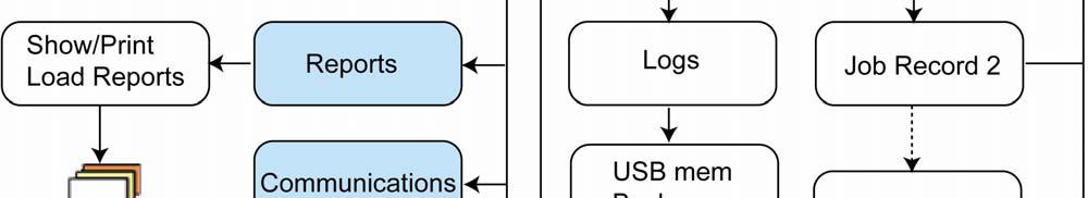
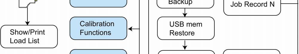
46 OPERATOR S MANUAL page 45 CHAPTER 5 Maintenance Open Main Menu Service, refer chapter 2.1. Service Functions holds submenus for sensor test, log files, backup and restore log files/database, copy attachment calibration, and system information. Figure 5-1 Service functions. Data Monitor is for sensor test after e.g. installation and service. Data monitor and sensor readings are described in the LOADTRONIC 3 Installation Guide. Logs holds a complete history of the LOADTRONIC 3 operations: LoadList, Event list, Error list, and a combined list of these three lists. These files are used for e.g. analysis of system errors. USB MEM Backup is used to store backup of logs, database, calibration details and other system files. USB MEM Restore is used for retrieving logs, database, calibration details and other system files after service and software upgrade of the system. Copy Attachment is used to copy calibration details between attachments.

47 Fairbanks Scales page 46 System Information holds information about e.g. software versions and legal system files. 5.1 Load List, Event List and Error List There are 4 lists available: Loadlist, Event list, Error list and a Combined list of these three lists. Press Next/F4 to toggle between the lists. Press /F2 and /F3 to page up and -down in the list. Press the up- and down arrows to move up and down a single entry. Errors/failures are listed in a red font. For backup of the logfiles, refer chapter 5.2. The Loadlist is a list of each recording, holding information about the total load, number of buckets delivered, and date/time of the recording, refer Figure 5-2. Loadlist is a compressed list of the information given in the customer report, refer chapter LOADTRONIC 3 gives a warning in the top line at system start up when the Loadlist is more than 95% full, refer chapter 3.13 and chapter 4.2. Figure 5-2 Loadlist. The Event list holds information about every event performed by the system: calibration, backup, changing of legal system parameters etc.

48 OPERATOR S MANUAL page 47 The Error list states system error, e.g. missing sensor, zeropoint failure etc. Figure 5-3 Event List. 5.2 Backup and Restore Logfiles, Database and System Files We recommend that you perform a backup of log files (refer chapter 5.1), database (all editable text fields) and system files (calibration and configuration details) regularly, and that you store a backup after a calibration of the attachment. The database and system files can be retrieved using the restore function. The function is useful for e.g. retrieving the original calibration after a service/software upgrade of the system. When performing backup to a USM MEM device files will be copied to a directory called \Loadtronic\ID_NNN; NNN is the LOADTRONIC ID number given in Parameter Setup I. If the LOADTRONIC ID number is 001 (default number), the directory name will be \Loadtronic\ID_001. By using different ID numbers for each LOADTRONIC 3, the same USB MEM device can be used to backup several LOADTRONIC 3 systems without loosing data. The Restore function will only copy files from the USB MEM device with the corresponding directory name, hence backup from a LOADTRONIC 3

49 Fairbanks Scales page 48 device with ID number 001 will only restore files from the \Loadtronic \ID_001 directory. Perform a backup: 1. Open Main Menu Service USB MEM Backup, refer chapter Select which files to backup: Logs, Database and/or System files, refer Figure Press Enter/# to perform the backup. Figure 5-4 Backup. Retrieve details: 1. Open Main Menu Service USB MEM Restore, refer chapter Select which files to restore: Database or System Files, refer Figure 5-5. Note! To restore calibration data, enable the calibration switch, refer Figure Press Enter/# to perform the restore function.
50 OPERATOR S MANUAL page 49 Figure 5-5 Restore. 5.3 Copy Calibration Details The attachment descriptions are stored in ID number 1 to 10; calibration details are stored in corresponding A1 to A10. Calibration details stored in e.g. A1 can be copied to e.g. A2 for backup, refer Figure 5-6. Procedure for copying attachment: 1. Open Main Menu Service Copy Attachment, refer chapter Use the up- and down arrows to select the desired attachment ID from which calibration details are copied from. 3. Press Next/F4 to toggle between the attachment source and destination 4. Use the up- and down arrows to select the desired attachment ID to which calibration details are copied to. 5. Press Enter/# to copy. The calibration switch must be enabled, refer Figure 1-1.

51 Fairbanks Scales page 50 Figure 5-6 Copy attachment. 5.4 System Information System information holds two pages displaying information about software version, main unit serial number, OIML requirements, power supply, operating ranges, and checksum information on legal system files, refer Figure 5-7 and Figure 5-8. Press Next/F4 to toggle between the two pages. Figure 5-7 System Information, page 1.

52 OPERATOR S MANUAL page 51 Figure 5-8 System Information, page 2.