SPECIFICATION MODEL : SPHWHTHAD603
|
|
|
- Doris Welch
- 5 years ago
- Views:
Transcription
1 Rev :00 ISSUE NO : DATE OF ISSUE : 10.Feb.2011 SPECIFICATION MODEL : SPHWHTHAD603 HIGH POWER HV-AC LED CUSTOMER : Preliminary CUSTOMER CHECKED CHECKED APPROVED DRAWN SAMSUNG LED CHECKED(Sales) CHECKED(Quality) APPROVED SAMSUNG LED CO,.LTD. HV-AC LED 1
2 Contents 1. Product Outline Absolute Maximum Rating Characteristics Typical Characteristic Graphs Outline Drawing & Dimension Package Structure Solder Conditions Reliability Test Items & Conditions Circuit Design - Package and PCB Taping Dimension Label Structure Lot Number Reel Packing Structure Aluminum Packing Bag Precaution For Use Revision history HV-AC LED 2
3 1. Product Outline 1) Features ㆍ Plastic Molded Lead Frame Type : 12.4 mm (L), 11.4 mm (W), 4.38 mm (T) ㆍ SMD Type : 1 Heat Pad and 4 Electrical Pad ㆍ Beam View Angle( θ)* :136 ㆍ High Power / Brightness Chip & Long Time Reliability 2) Applications ㆍ Indoor & Outdoor lighting ㆍ Direct AC power source plug-in (110Vac, 220Vac) View Angle describes the spatial intensity distribution and is the difference between the angles corresponding to 50% of the maximum intensity. (Full Width Half Maximum) 2. Absolute Maximum Rating Parameter Value Unit Operating Voltage 250 V[RMS] Power Dissipation 6.5 W LED Junction Temperature (T J ) 125 Operating Temperature Range (T OPR ) Storage Temperature (T STG ) ESD Sensitivity ± 3,000V HBM - 3. Characteristics 1) Electro-Optical properties (T a = 25 ) Parameter Symbol Condition Min. Typ. Max. Unit Luminous Flux Φ V lm CCT CT K I F=22mA(rms)/220Vac CRI Ra I F=44mA(rms)/110Vac Power Dissipation P 3.3 W Operating Frequency fo 50/60 Hz Parameter Symbol Condition Min. Typ. Max. Unit Luminous Flux Φ V lm CCT CT K I F=22mA(rms)/220Vac CRI Ra I F=44mA(rms)/110Vac Power Dissipation P 3.3 W Operating Frequency fo 50/60 Hz Tolerance : ±10% HV-AC LED 3
4 2) Chromaticity Coordinates (T a = 25 ) HV-AC LED 4
5 ㆍ 5000K Table Rank CIE X CIE Y Table Rank CIE X CIE Y R R R R K K R R R R R7 R6 R3 R2 R4 R1 R5 R8 HV-AC LED 5
6 ㆍ 2700K TABLE Rank CIE X CIE Y TABLE Rank CIE X CIE Y 2700K W1 W2 W3 W W W K W W W3 W4 W5 W6 W1 W2 W7 W8 HV-AC LED 6
7 3) Luminous Flux (T a = 25 ) (Unit, lm) Parameter Symbol Condition * Rank Min. Typ. Max. CCT Luminous Flux Φ V I F =22mA(rms)* /220Vac I F =44mA(rms) /110Vac M N P Q K Parameter Symbol Condition * Rank Min. Typ. Max. CCT Luminous Flux Φ V I F =22mA(rms) /220Vac I F =44mA(rms) /110Vac G H J K K Tolerance : ±10% * Sorting is IF=22mA(rms) 4) V F Bin (T a = 25 ) Symbol Condition Rank Min. Typ. Max. Unit Vf I F = 22mA(rms) F F F Vac (rms) Tolerance : ±5V 5) Resistor Table Resistor Value Parallel Connection Series Connection Vf 100Vac 110Vac 120Vac 220Vac 230Vac 240Vac F ,200 2,620 3,100 F ,100 2,560 3,000 F ,000 2,500 2,900 Unit Ω LED Power dissipation Tolerance : ±7% HV-AC LED 7
8 4. Typical Characteristic Graphs 1) AC voltage operating characteristic Ballast Resistor Total Power Consumption = Power_LED + Power_Resistor Power_LED = Total Power - I 2 R < Power consumption vs. Operating current > < LED Input Power vs. Generated Heat > Total Thermal Power = LED + Resistor Thermal power of the LED is the vertical axis of the above graph. Thermal power of the resistor is Current 2 X Resistance. Resistor value and type must be selected depending on the operating condition. HV-AC LED 8
9 2) IV characteristic (operating in AC voltage, T a = 25 ) 3) Optical characteristic (operating in AC voltage, T a = 25 ) Temperature is measured on PCB bottom surface. HV-AC LED 9
10 4) Typical Spatial Distribution 5) Spectrum Distribution HV-AC LED 10

 Bipolarity")


11 5. Outline Drawing and Pad Configuration Unit : mm Tolerance : ±0.1 Pad Function Bipolarity Bipolarity Thermal (Electrically Isolated) Bipolarity Bipolarity Pick and Place 1. Do not place pressure on the encapsulating resin It is recommended to use a pick&place nozzle with inside diameter at 9.2mm 2. The maximum compressing force is 20N on the polymer HV-AC LED 11
 2 Package Heat-Resistant Polymer 3 LED Chip GaN on Sapphire 4 WIRE Gold Wire 5 Encapsulation RESIN Silicone + Phosphor 6 Lens Silicone 250 Peak Temp.")
12 6. Package Structure NUMBER ITEM MATERIAL 7. Solder Conditions 1) Reflow Conditions (Pb-Free) Reflow Frequency : 2 time max FRAME Copper Frame(Silver Plated) 2 Package Heat-Resistant Polymer 3 LED Chip GaN on Sapphire 4 WIRE Gold Wire 5 Encapsulation RESIN Silicone + Phosphor 6 Lens Silicone 250 Peak Temp. : 260±5, Max. 10 sec Temperature[ ] Preheating : 150~180 Time above 220 : Max. 60 sec Max. 60 sec Max. Temp. gradient in cooling : -5 /sec 50 60~120 sec Time[sec] 2) For Manual Soldering Not more than 5 300, under soldering iron. HV-AC LED 12
13 8. Reliability Test Items and Conditions 1) Test Items Test Items Room Temperature life test High Temperature humidity life test High Temperature life test Low Temperature life test High Temperature Storage Low Temperature Storage Thermal Shock Temperature humidity Cycle On/Off test Test Conditions Test Hours/Cyc les 25, IF = Max AC 25mA(rms) 1,000 h 85, 85% RH, IF = Max AC 25mA(rms) 1,000 h 85, IF = Max AC 25mA(rms) 1,000 h -40, IF = Max AC25mA(rms) 1,000 h 120 1,000 h -40 1,000 h -40 / 120, each 30 min -40 / 85, each 20 min, 100 min transfer Power On/off each 5 min, AC 20 ma 200 cycles 100 cycles Reflow (Pb-Free) Peak 260±5 for 10 sec 3 times ESD(HBM) R1 : 10 MΩ, R2 : 1.5 kω, C : 100 pf 5 times (± 2 kv ) Surge Line to Line 1 kv 2) Criteria for Failure Item Symbol Test Condition Limit Min Max Forward Voltage VF IF = 22 ma (rms) - U.S.L.*1.2 Luminous Flux ΦV IF = 22 ma (rms) L.S.L.*0.7 - U.S.L : Upper Standard Level, L.S.L : Lower Standard Level HV-AC LED 13


14 9. Circuit Design - Package and PCB This HV-AC LED can be used for both 110Vac and 220Vac depending on the PCB circuit design. Creepage distance between edge and Cu pattern should be greater than 5mm. Schematic Circuit Connection (Example) PCB Pattern Circuit (Example) To improve protection against surge, divide resistor value in 3.5) Resistor Table (Page 6) by 2 and use half and half on both sides as illustrated in the figures above. HV-AC LED 14
 330 ± 1 80 ± 1 25 ± 0.5 13 ± 0.3 29.5 ± 1 (1) Quantity : 1,000 Pcs / 13\" Reel.")
 Packaging : P/N, Manufacturing data Code No.")
15 10. Taping Dimension Polarity End Start More than 100 mm Mounted with More than (100~200) mm Leading part more than Unloaded tape LED Unloaded tape (200~400) mm Symbol A B C W1 W2 Dimension( mm ) 330 ± 1 80 ± 1 25 ± ± ± 1 (1) Quantity : 1,000 Pcs / 13" Reel. (2) Cumulative Tolerance : Cumulative Tolerance/10 pitches is less than ±0.2 mm (3) Adhesion Strength of Cover Tape : Adhesion strength to be N when the cover tape is turned off from the carrier tape at 10 angle to be the carrier tape. (4) Packaging : P/N, Manufacturing data Code No. and quantity to be indicated on a damp proof Package HV-AC LED 15
16 11. Label Structure SPHWHTS8N103 IIIIIIIIIIIIIIIIIIIIIIIIIIII A2LBK3 A2LBK3 XXXX / I / XXXXpcs IIIIIIIIIIIIIIIIIIIIIIIII Rank Code /A2/ : VF Rank (refer to page 3) /LB/ : Chromaticity Coordinate Rank, CIE (refer to page 4) /K3/ : Luminous Flux (refer to page 4) 12. Lot Number The Lot number is composed of the following characters / I / 1000PCS : Production Site (S:SAMSUNG LED, G:Gosin China) : L (LED) : Product State (A:Normality, B:Bulk, C:First Production, R:Reproduction, S:Sample) : Year (S:2008, T:2009, U: ) : Month (1 ~ 9, A, B) : Day (1 ~ 9, A, B ~ V) : SAMSUNG LED Product Number (1 ~ 999) : Reel Number (1 ~ 999) HV-AC LED 16
 Inner Box Material : Paper(SW3B(B)) SIZE( mm ) TYPE L W H 13inch 335 45 335 SPHWHTS8N103")
17 13. Reel Packing Structure 1) Reel SPHWHTS8N103 IIIIIIIIIIIIIIIIIIIIIIIIIIII A2LBK3 A2LBK3 XXXX / I / XXXXpcs IIIIIIIIIIIIIIIIIIIIIIIII 2) Aluminum Bag SPHWHTS8N103 IIIIIIIIIIIIIIIIIIIIIIIIIIII A2LBK3 A2LBK3 XXXX / I / XXXXpcs IIIIIIIIIIIIIIIIIIIIIIIII Humidity Indicator Card Silica gel 3) Inner Box Material : Paper(SW3B(B)) SIZE( mm ) TYPE L W H 13inch SPHWHTS8N103 IIIIIIIIIIIIIIIIIIIIIIIIIIII A2LBK3 A2LBK3 XXXX / I / XXXXpcs IIIIIIIIIIIIIIIIIIIIIIIII H HP LED W L HV-AC LED 17
18 4) Carton Box Material : Paper(SW3B(B)) SIZE( mm ) TYPE L W H 13inch SPHWHTS8N103 IIIIIIIIIIIIIIIIIIIIIIIIIIII A2LBK3 A2LBK3 XXXX / I / XXXXpcs IIIIIIIIIIIIIIIIIIIIIIIII H HP LED W L HV-AC LED 18


19 14. Aluminum Packing Bag SPHWHTS8N103 IIIIIIIIIIIIIIIIIIIIIIIIIIII A2LBK3 / I / XXXXpcs IIIIIIIIIIIIIIIIIIIIIIIII A2LBK3 XXXX Silica gel & Humidity Indicator Card in Aluminum Packing Bag HV-AC LED 19
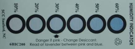
20 15. Precaution for Use 1) For over-current-proof function, customers are recommended to apply resistors to prevent sudden change of the current caused by slight shift of the voltage. 2) This device should not be used in any type of fluid such as water, oil, organic solvent, etc. When washing is required, IPA is recommended to use. 3) When the LEDs illuminate, operating current should be decided after considering the ambient maximum temperature. 4) LEDs must be stored in a clean environment. If the LEDs are to be stored for 3 months or more after being shipped from SAMSUNG LED, they should be packed by a sealed container with nitrogen gas injected. (Shelf life of sealed bags : 12 months, temp. 0~40, 20~70%RH) 5) After storage bag is open, device subjected to soldering, solder reflow, or other high temperature processes must be: a. Mounted within 168 hours (7days) at an assembly line with a condition of no more than 30 /60%RH, b. Stored at <10% RH. 6) Repack unused Products with anti-moisture packing, fold to close any opening and then store in a dry place. 7) Devices require baking before mounting, if humidity card reading is >60% at 23±5. 8) Devices must be baked for 24hours at 65±5, if baking is required. 9) The LEDs are sensitive to the static electricity and surge. It is recommended to use a wrist band or anti-electrostatic glove when handling the LEDs. If voltage exceeding the absolute maximum rating is applied to LEDs, it may cause damage or even destruction to LED devices. Damaged LEDs may show some unusual characteristics such as increase in leak current, lowered turn-on voltage, or abnormal lighting of LEDs at low current. HV-AC LED 20
21 10) When handling LED with tweezers, the LED Should only be held by the polymer body, not by the encapsulant or LENS. 11) The use of appropriate nozzle for the LED recommended. For the recommended nozzle size, refer to the figure at the below. Inner diameter of nozzle Φ9.2mm 12) Do not stack assembled PCBs together. Since silicone is a soft material, abrasion between two PCB assembled with silicone encapsulated LED might cause catastrophic failure of the LEDs due to damage to encapsulant and wire and LED detachment. HV-AC LED 21
22 Revision History (Model : HV-AC LED) Date Revision History Author Drawn Approved Initial Edition Y.J. Lee H.K. Kim Second Edition Y.J. Lee I.H. Choi Third Edition Y.J. Lee I.H. Choi HV-AC LED 22