SKATEWHEEL FLOW RACK
|
|
|
- Preston Powers
- 5 years ago
- Views:
Transcription
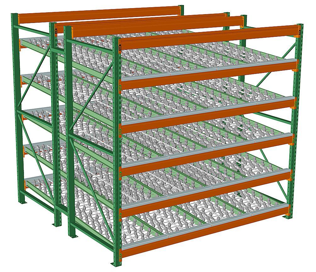
1 SKATEWHEEL FLOW RACK
2 2 ASSEMBLY INSTRUCTIONS: Steel King Industries recommends that this product be assembled only by qualified personnel, experienced in assembly of storage racks, and knowledgeable of all safety regulations and practices. These instructions are intended only for use by qualified individuals using all proper safety equipment. These storage racks are extremely heavy, and if not properly secured during installation and assembly could fall, possible causing injury or death as well as damage to property. Contact Steel King Industries or your local Steel King Representative for the name and contact information of a qualified installer. Users of this information agree to indemnify and hold harmless Steel King Industries from any and all liability. Installation Note: Do not install racks outdoors, unless specifically designed by Steel King for this purpose. Outdoor usage requires consideration of wind loads, snow loads, etc., which are not normally considered in rack design. Pallet Rack User s Manual Steel King Industries recommends that all users of Steel King manufactured storage racks obtain, read and understand Steel King s Pallet Rack User s Manual. Copies of Steel King s Pallet Rack User s Manual are free of charge and can be obtained by contacting Steel King Industries at: Steel King Industries Inc 2700 Chamber St Stevens Point, WI (800) info@steelking.com Electronic versions are available at:

3 3 Step #1: Check the Material A. Check to make certain that all materials have been received. Materials should be checked against the packing lists and Bill of Lading. B. Notify the shipper immediately of any shortages or product damage. Step #2: Check the Area: A. Clear the area where the rack system is to be located. B. Check the area for all obstructions, such as lights, heating ducts, pipes, building columns, etc., to insure a clear area for the installation of the storage rack. Step #3: Lay Out floor: Recommended tools: Tape Measure Chalk Line A. Establish the rack lay out by determining the aisle dimensions and the rack position. B. Snap a chalk line establishing the front edge of the upright bases. The chalk line should run the entire length of the row of rack.
4 4 Step #4: Assemble First Bay: Recommended Tools Lift truck A. Stand up two upright frames and separate by the length of the load beams. B. Using one of the 3-1/2 beams, place rivets from beam clips into top most of tear drop holes (wider part of hole) on face of upright frames. Slide beam downward into tear drop holes until completely seated and safety clip engages. See figure below. Insert beam clip rivet into top of tear drop hole. Slide beam downward until completely seated and safety clip engages. D. Install second beam on the opposite side of upright frames, at the identical height of first beam.
5 5 Step #4: Assemble First Bay Continued: E. Move and align bay so that front edge of upright bases is on chalk line. Diagonal Bracing Aisle Side Chalk Line Upright frames should be positioned so that the lowest diagonal bracing is pointed downward toward aisle side F. Assemble second set of uprights in same manner and move behind first bay. G. Install rack spacers and midpoint of both top and bottom halves of the uprights on both sides of the bays H. Install subsequent beam levels from the lowest level to the highest level, with 4-1/2 beams on the front and all but (2) of the 3-1/2 beams on the rear. (See note below.) The remaining 3-1/2 beams will be placed on the inner facing sides of uprights at the approximate midpoint of the height of the upright, but not impeding product flow once skatewheel tracks are in place. Note: It is recommended that a lift truck be used to stand and position frames. Note: Set up front and rear beams using the recommended vertical drop rate of ½ inch per 1 ft. of depth for best gravity feed, with highest point at the rear and lowest at the front.
6 6 Step #5: Shim, Plumb, and Anchor: Recommended tools: Level, Air compressor, 3/4 drive impacts or equivalent A. Make sure that the bay is square and plumb before anchoring. Plumb Note: It is very important that the rack structure be installed in a plumb, level, and square condition. Since few floors are perfectly flat, shimming of the racks is frequently required. A four foot long carpenter's level is a good choice for checking level and plumb conditions on storage racks of average proportions. A vertical tolerance of 1/8" in 4 feet (or other as specified on Steel King installation drawings) is generally acceptable. B. Use shims as required. Shims are available in 1/8 and 1/16 thicknesses. C. The first bay of each row must be anchored to the floor to insure proper placement of the rack to the floor layout. D. Each upright frame has 2 footplates, each with 2 anchor holes for floor anchoring. Under normal (non seismic) circumstances, only 1 anchor is required for each footplate. Non Seismic Anchoring Diagrams 1 5/8 x 3 wide Upright Column 3 X 3 wide Upright Column Step #5: Shim, Plumb, and Anchor:
7 7 Step #5: Shim, Plumb, and Anchor: Seismic Anchoring Diagrams 3 x 3 wide Upright Column 5 x 7 x 3/8 Base Plate or 5 x 7 x ½ Base Plate (2) ½ x 4 1/2 I.C.C Approved Anchors per Base Plate Anchoring Notes: Every column of each rack frame must be anchored to an adequate concrete floor. The normal anchor connection is (1) one ½" diameter x 3 3/4" concrete expansion anchor per column footpad, or as indicated on the Steel King installation drawings. Seismic uprights, those with 5 x 7 base plates, utilize (2) two ½ diameter x 4 ½ I.C.C. approved concrete expansion anchors per column footpad. Anchor bolts are not included with Steel King rack systems unless specifically detailed on the Bill of Materials. Since anchor bolts vary in strength, if you are purchasing your own anchor bolts, contact Steel King or your Steel King Distributor for minimum anchor specifications for your installation. Since concrete floors vary greatly in design and load carrying capacity, Steel King cannot guarantee that a particular concrete slab is adequate to support a particular rack installation. The characteristics of the slab should be obtained from the building architect before the racks are specified, so that the rack supplier can design the rack to suit the slab.
8 8 Step #6: Install Remaining Bays: A. Follow the same procedure as Step #4 using common upright frames for each bay. Step #7: Accessories: A. When row spacers are required, each component must have (1) ½ diameter x 3 3/4 bolt and ½ nut per connection. Use a minimum of (2) row spacers up to 120 high, (3) up to 216 high and (4) up to 312 high. Vertical placement of row spacers should be in line with upright column s horizontal bracings. B. The pallet supports are installed with one tek screw on each end. Hat Style (PSH part numbers) Pallet Supports
9 9 Step #6: Install Remaining Bays continued: Waterfall (PSW part numbers) Pallet Supports C. Tighten all accessory nuts and bolts (row spacers) and double check anchor connections to complete the installation process. Capacity Plate Note: Installation of "capacity plates" is strongly recommended. These plates should identify the characteristics for which the rack was designed, such as load size, load weight, and rack configuration. These plates are very useful for communicating safe loading information to both present and future users. Several signs should be prominently located for easy visibility, and be permanently affixed to the rack structure. Appropriate signs can be obtained locally, through industrial mail order catalogs, or from Steel King or your Steel King Distributor. Step #8: Cleanup: A. Dispose of all dunnage, strapping and debris. Sweep the floor with a broom if necessary.
10 10 Determining Storage Rack Capacity To determine the load capacity of your storage rack: A. Determine the maximum distances between shelf/beam levels. B. Determine the distance from the floor to the first shelf/beam level. C. Compare distances computed in Steps A & B; use whichever figure is greater as the Maximum Vertical Beam Spacing in the chart below. Steel King Upright Frames Upright Frame Post Type RTFAG RTFBG RTFBG SEISMIC RTFBW SEISMIC Post Width 3 Inches 3 Inches 3 Inches 3 Inches Maximum Vertical Beam Capacity (pounds) Spacing: 48 21,860# 31,420# 54 19,440# 28,490# 60 17,050# 25,530# 66 14,740# 22,600# 72 12,540# 19,770# 78 10,700# 17,050# 84 9,250# 14,740# 90 8,060# 12,870# 96 7,100# 11,330# Over 96 Consult Steel King Capacity ratings for seismic frames are based on installation location, upright height and vertical beam spacing. Please consult Steel King.
11 11 Chart Notes: 1) Capacities based upon interior usage. 2) Capacities are for selective rack only. 3) The above capacities do not consider seismic loading. 4) Each column/post of each frame MUST be anchored to an adequate concrete floor. 5) Capacities based upon installation in a plumb condition. 6) Capacities are total per upright, assuming equal loading on both posts. In essence, the listed capacity is the maximum weight that may be stored within one individual rack bay. DO NOT double the capacity of each upright frame when calculating a single bay s capacity. 7) Capacities are to be reduced to account for the weight of the rack system; deduct the weight of beams, frames, decking, and accessories. 8) Your local Building Inspector may require adherence to a specific code, which may reduce the listed capacity. Verify the applicable code and the capacity rating under that code with Steel King or your Steel King Distributor. If any of these conditions do not apply to your application, or if you are unsure if they apply, DO NOT USE CHART; in those cases, consult Steel King Engineering department for design information. Changing the configuration (such as adjusting storage levels) can adversely affect the load carrying capacity and reduce the structural integrity of the rack system. Before adjusting the rack configuration, contact Steel King or your Steel King Distributor, to verify the safety and structural adequacy of the new configuration. Have questions about pallet racks? Answers to Frequently Asked Questions may be found at the following website: If you have any further questions, contact your local Steel King Representative for customer assistance or contact Steel King Industries directly at (800)
12 12 WARNING: INSTRUCTIONS FOR ASSEMBLY ARE SET FORTH ON THESE PAGES. PROPER ASSEMBLY IS THE RESPONSIBILTY OF THE PURCHASER AND IS NOT COVERED BY ANY WARRANTY OF THE SELLER. BUYER IS CAUTIONED NOT TO SUBSTITUTE PARTS OR HARDWARE. SELLER DISCLAIMS ALL LIABILITY WITH RESPECT TO ANY SUBSTITUTION OF PARTS OR HARDWARE NOT APPROVED IN WRITING BY SELLER. THE INSTALLATION DETAIL DRAWINGS THAT FOLLOW ARE INTENDED AS BASIC GUIDES TO INSTALLATION OF THE STANDARD COMPONENTS. DEPENDING UPON THE SPECIFICS OF THE SYSTEM, THERE MAY BE LIMITIATIONS REGARDING THE USE OF THESE STANDARD COMPONENTS AND/OR A REQUIREMENT FOR SPECIAL INSTALLATION TECHNIQUES. ADDITIONAL INFORMATION IS FOUND IN STEEL KING PRICE BOOKS, PUBLISHED TECHNICAL DOCUMENTS, COMPREHENSIVE INSTALLATION DRAWINGS, AND OTHER MATERIALS. Follow instructions that came with the flow tracks for assembly of the skatewheel conveyor track. Once assembled, simply drop in place in assembled pallet rack.