FPU SYSTEMS OPERATION MANUAL BOH OFFICE MODULE (INCLUDING REPAIR PARTS & SPECIAL TOOL LIST) BOH FPU Field Pack-up Units
|
|
|
- Ira Alan Hopkins
- 5 years ago
- Views:
Transcription
 674-0725 http://www.bohfpusystems.")
1 FPU SYSTEMS OPERATION MANUAL BOH OFFICE MODULE (INCLUDING REPAIR PARTS & SPECIAL TOOL LIST) BOH FPU Field Pack-up Units OFFICE MODULE. BOH ENVIRONMENTAL LLC Avion Parkway, Suite 220 Chantilly, Va POC Doug Cresap (985) BOH Environmental LLC
2 This page was intentionally left blank

3 WARNING SUMMARY This warning summary contains general safety warnings and hazardous materials warnings that must be understood and applied during operation and maintenance of this equipment. Failure to observe these precautions could result in serious injury or death to persons using equipment. WARNING Forklift operator should always use module forklift pockets when moving Office Module to prevent tipping. Ground guides must insure no personnel go underneath office module during movement operations. Failure to comply could cause injury, death or damage to the equipment. WARNING Use extreme caution when loading or unloading Office Module from and into FPU containers, other containers and transport vehicles. Forklift operator should maintain visual contact with ground guides at all times. Ground guides should never come between the module and container during loading process. If visual contact with ground guide is lost, immediately suspend all operations, turn off forklift and set emergency brake. Failure to comply could cause serious injury, death or damage to the equipment. WARNING Always follow standard forklift procedures. A tilt hazard exists when forklift operators try to lift an office module, without inserting forklift tines into module forklift pockets. Operators should always keep loads low and close to the forklift carriage. Operators should never travel when the load is in the fork s extended position. Ensure hands, feet and limbs are clear of the container and components during any forklift or lifting operation. Failure to comply could cause injury or damage to the equipment. WARNING Always ensure the inside of the Office Module is free of debris, grease, and foreign objects. Failure to comply could cause injury to personnel. WARNING The office module is heavy and could cause injury or death if it falls onto or strikes personnel. A tilt hazard exists when either the module is not properly locked down to the FPU container twistlock device or is not properly secured within other types of containers. Ensure that all internal equipment is properly locked, latched and secured in place prior to any movement of the office module. WARNING Personnel shall never climb on top of the office module as the roof is not designed for this. A slip hazard may also occur if the top of the module is wet. a


4 WARNING SUMMARY This warning summary contains general safety warnings and hazardous materials warnings that must be understood and applied during operation and maintenance of this equipment. Failure to observe these precautions could result in serious injury or death to persons using equipment. Container Overhead Power Line Warning WARNING Overhead power lines and obstructions can cause serious injury or damage to property. Forklift operators, truck drivers, and ground guides should always clear overhead when moving the office module. WARNING Fluorescent tubes contain hazardous material. For proper disposal of fluorescent tubes, refer to DOD M page WARNING Protective gloves should be worn when handling metal parts in high temperatures. Failure to wear gloves may result in burning or blistering of the skin upon contact. WARNING Protective gloves should be worn when handling metal parts in below freezing temperatures. Failure to wear gloves may result in skin freezing to the metal upon contact and cause tearing of the flesh when attempting to pull away from the metal. WARNING The office module is NOT designed to be operated in contaminated NBC Environments. The FPU is designed to operate outside an established NBC safety perimeter. Do not operate the FPU in contaminated NBC environments. b
5 GENERAL WARNINGS HEAVY PARTS - heavy object on human figure shows that heavy parts present a danger to life or limb. HEAVY PARTS - heavy object pinning human figure against wall shows that heavy, moving parts present a danger to life or limb. HEAVY PARTS - hand with heavy object on top shows that heavy parts can crush and harm. HEAVY PARTS - foot with heavy object on top shows that heavy parts can crush and harm. SLICK FLOOR - wavy line on floor with legs prone shows that slick floor presents a danger for slipping or falling. ELECTRICAL - electrical wire to arm with electricity symbol running through human body shows that shock hazard is present. CRYOGENIC - hand in block of ice shows that the material is extremely cold and can injure human skin or tissue. CHEMICAL - drops of liquid on hand shows that the material will cause burns or irritation to human skin or tissue. EYE PROTECTION - person with goggles shows that the material will injure the eyes. HOT METAL SURFACES- Metal surfaces may become hot in extreme heat areas, prolonged contact may cause burning or blistering of the skin. c
6 This page was intentionally left blank
7 FPU SYSTEMS OPERATION MANUAL BOH OFFICE MODULE (INCLUDING REPAIR PARTS & SPECIAL TOOL LIST) BOH FPU Field Pack-up Units Manual Table of Contents REPORTING ERRORS AND RECOMMENDING IMPROVEMENTS You can help improve this manual. Please let us know if you find any mistakes or if you know of a way to improve the procedures. You may send in your recommended changes by directly to: dcresap@bohfpusystems.com. A reply will be furnished directly to you. Approved for public release; distribution is unlimited. TABLE OF CONTENTS WP Sequence No. WARNING SUMMARY... a HOW TO USE THIS MANUAL... iii CHAPTER 1 INTRODUCTORY INFORMATION WITH THEORY OF OPERATION General Information Theory of Operation Office Module Orientation Movement and Transport Equipment Characteristics, Components & Accessories Equipment Data Labels, Identifications & Markings CHAPTER 2 OPERATOR INSTRUCTIONS Preparation for Movement and Transport Operation of Office Module Office Module Roof Electrical System Operation of Internal Components Operation under Unusual Conditions CHAPTER 3 - TROUBLESHOOTING PROCEDURES Introduction Troubleshooting Index Troubleshooting Procedures Table CHAPTER 4 OPERATOR MAINTENANCE INSTRUCTIONS Introduction to Preventative Maintenance Checks and Services (PMCS) PMCS Table Cleaning and Lubricating Tables Exterior Inspection Interior Inspection Electrical System Inspection i
8 CHAPTER 5 UNIT MAINTENANCE INSTRUCTIONS Rivet Replacement Exterior Repair Interior Repair Electrical Repair CHAPTER 6 PARTS SUPPORTING INFORMATION Introduction to Maintenance Allocation Chart (MAC) Maintenance Allocation Chart (MAC) Introduction to Repair Parts & Special Tool List Office Module Exterior Repair Parts Office Module Interior Repair Parts Office Module Interior Electrical Components OFFICE MODULE 01 Office Module Interior Electrical Components 0101 Rear Wall Electrical 0102 Desk Side Wall 0103 Light Switch 0104 Lights 02 Interior Parts 0201 Desk 0202 File Cabinet 0203 Upper Shelf 0204 Storage Cabinet 03 HVAC 04 Roof Elevation Parts 0401 Jack Assembly 0402 Wall Lock Assembly 05 Office Module Exterior 0501 Door Assembly 0502 Ground Lug Kit NSN Index Part Number Index REAR MATTER BOH Product Warranty Metric Conversion Chart Appendices Appendix.Frigidaire HVAC Operation Manual ii
9 HOW TO USE THIS MANUAL This manual contains general information, operating instructions, Preventative Maintenance Checks and Services (PMCS), and maintenance/repair instructions for the Office Module. Front matter consists of front cover, warning summary, title block, table of contents, "how to use this manual" pages, and provides information on the Office Module and its associated equipment. Chapter 1 provides equipment description and data as well as basic the theory of operation for the Office Module. Chapter 2 provides instructions for operating under usual and unusual conditions. Chapter 3 contains troubleshooting procedures authorized at the Operator and Unit level. Chapter 4 contains Preventative Maintenance Checks and Services (PMCS) and Operator Maintenance Instructions. Chapter 5 contains Unit Maintenance Instructions. Chapter 6 contains the Maintenance Allocation Chart (MAC); it also includes the Repair Parts & Special Tools List (RPSTL) that identifies parts or tools unique to the operation and maintenance of the Office Module and components. Manual Organization and Page Numbering This manual is divided into six major chapters that detail the topics mentioned above. Within each chapter are work packages covering a wide range of topics. Each work package is numbered sequentially at page 1, and has its own page numbering scheme that is independent of the page numbering used by other work packages. Each page of a work package has a page number of the form "XXXX YY-ZZ", where "XXXX YY" is the work package number (e.g is work package 10) and "ZZ" represents the number of the page within that work package. Blank pages will be labeled; This page was intentionally left blank. Finding Information The Table of Contents permits the reader to quickly find information in the manual. The reader should start here first when looking for a specific topic. The Table of Contents lists the topics contained within each chapter and the work package sequence number where it can be found. Types of Notations Warnings - Warnings are posted immediately prior to text covering any area that would present a situation that may result in injury or death. Compliance is mandatory. Cautions - Cautions will be found on the same page and preceding the text covering any area that would present a situation that may result in damage to equipment. Notes - Notes will precede text covering an area with the intent to alter normal procedures for unique situations or equipment, or point out areas of special concern. iii
10 This page was intentionally left blank
11 FPU SYSTEMS OPERATION MANUAL BOH OFFICE MODULE (INCLUDING REPAIR PARTS & SPECIAL TOOL LIST) BOH FPU Field Pack-up Units CHAPTER 1 INTRODUCTORY INFORMATION WITH THEORY OF OPERATION
12 This page was intentionally left blank
13 INTRODUCTORY INFORMATION WITH THEORY OF OPERATION FPU SYSTEMS OPERATION MANUAL BOH OFFICE MODULE (INCLUDING REPAIR PARTS & SPECIAL TOOL LIST) BOH FPU Field Pack-up Units GENERAL INFORMATION SCOPE Equipment Covered This technical manual contains instructions for the operation, preventative maintenance, and recommended Unit/Direct Support corrective maintenance for the BOH Office Module and the associated equipment. Type of Manual This is an Operator, Unit and Direct Support, Operation and Maintenance Manual. Equipment Name, Part Number and NSN Containerized Mission System PART NUMBER NSN Office Module (Green/Tan) END OF WORK PACKAGE
14 This page was intentionally left blank
 with adjustable height (external) up to 93 H.")
 with automatic switch for low-voltage white/red lighting.")
15 INTRODUCTORY INFORMATION WITH THEORY OF OPERATION FPU SYSTEMS OPERATION MANUAL BOH OFFICE MODULE (INCLUDING REPAIR PARTS & SPECIAL TOOL LIST) BOH FPU Field Pack-up Units THEORY OF OPERATION Office Module Description The BOH Office Module is a 2-person mobile work station which measures 69 W x 73 H x 88 L (upper external unextended position) with adjustable height (external) up to 93 H. Features quick-disconnect 30amp power, 7-outlet surge strip, Ethernet port, 2 rolling office chairs, one storage cabinet, 2 file drawers, retractable HVAC, overhead shelf w/ securing straps, seamless desktop, FRP interior walls and ceiling, and 2-stage door (at one end) with automatic switch for low-voltage white/red lighting. A single unit (unextended) can fit inside an FPU 8-2 or the 8-foot section of an FPU 20-1 or 20-2 for transport. It can also be transported inside an FPU 8-4 or the 8-foot section of an FPU 20-3 when installed with removable cradles. The office module has 4 fork pockets, two on each side, for forklift transport and movement outside of the FPU container. Compatible Shipping Containers System BOH FPU Cargo Container Systems are a durable standardized storage and transport system capable of rapidly mobilizing material. These systems can be configured to store and transport small, medium, large, palletized and bulk material. The FPU-8-2/BOH-CARGO-12-1 (Combination), FPU-8-4/BOH- CARGO-12-3 (Combination), FPU-20-1 & FPU-20-2 and FPU-20-3 containers are side-load containers. These container systems are ISO Certified and CSC Safety Approved and can be stacked nine high onboard commercial or MSC container ships. FPU-8-2/BOH-CARGO-12-1 (Combination) has a maximum capacity of 36,000 lbs., the FPU-8-4/BOH-CARGO-12-3 has a maximum capacity of 37,000 lbs., the FPU-20-2 has a maximum capacity of 33,000 lbs. FPU-20-1 has a maximum capacity of 52,900 lbs. and the FPU-20-3 has a maximum capacity of 37,000 lbs. The BOH FPU containers come in two color variations: Forest Green and Desert Sand. FPU 20-3 FPU 8-2 BOH CARGO 12-1 FPU 20-1 &2 BOH CARGO 12-3 FPU 8-4 END OF WORK PACKAGE
16 This page was intentionally left blank

17 INTRODUCTORY INFORMATION WITH THEORY OF OPERATION FPU SYSTEMS OPERATION MANUAL BOH OFFICE MODULE (INCLUDING REPAIR PARTS & SPECIAL TOOL LIST) BOH FPU Field Pack-up Units OFFICE MODULE ORIENTATION Office Module Orientation For proper operation of the office module, selecting a site to place the office module that is a reasonably level and smooth surface is essential. The HVAC unit is located in the rear of the office module on the wall opposite the door and adjacent to the desktop. The power and communications hookups are located in the rear of the container. Module Rear Shore Power Entry Door Module Front Office Module Section View (side wall, entry door and top ceiling component removed for clarity) END OF WORK PACKAGE
18 This page was intentionally left blank
19 INTRODUCTORY INFORMATION WITH THEORY OF OPERATION FPU SYSTEMS OPERATION MANUAL BOH OFFICE MODULE (INCLUDING REPAIR PARTS & SPECIAL TOOL LIST) BOH FPU Field Pack-up Units MOVEMENT AND TRANSPORT Movement and Transport The Office Module is provided with fork pockets on three sides of the container (rear and both sides) to facilitate lifting, positioning and loading of the modules into FPU containers for transport. The rear fork pockets are situated toward the right of the office module to account for the additional weight on the desk side of the module. Side fork pockets (both sides) Rear fork pockets (rear only) NOTE Top Ceiling Component and entry door removed for clarity CAUTION The Office Module should only be lifted by the fork pockets provided on the left side, right side or rear, never from the front

20 END OF WORK PACKAGE
 BOH FPU Field Pack-up Units EQUIPMENT CHARACTERISTICS, COMPONENTS & ACCESSORIES HVAC units The office module has a retractable")
 and door lighting interrupter switch (2) for activating red lighting")
21 INTRODUCTORY INFORMATION WITH THEORY OF OPERATION FPU SYSTEMS OPERATION MANUAL BOH OFFICE MODULE (INCLUDING REPAIR PARTS & SPECIAL TOOL LIST) BOH FPU Field Pack-up Units EQUIPMENT CHARACTERISTICS, COMPONENTS & ACCESSORIES HVAC units The office module has a retractable HVAC (8,000 BTU) unit. Lighting System CAUTION The HVAC unit must be extended in the out position before operating. The office module includes two 120 VAC fluorescent light fixtures (1) and door lighting interrupter switch (2) for activating red lighting feature
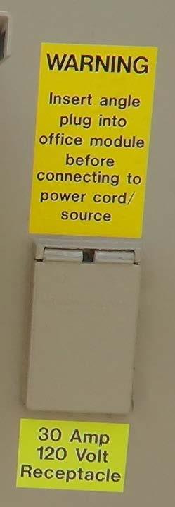
22 Exterior Connections The Office Module is equipped with a communication connection box (2) and power connection box (3) with protective weather covers, electrical cable, and external ground lug (4). There is also a cable passthrough port (1) for various other equipment connections Office Module Rear View WARNING The electrical ground must be established first to prevent electrical shock to personnel. A ground rod is not provided with the Office Module; grounding source must be provided. Consult an Army certified electrician MOS 21R or DOD equipment grounding safety procedures. END OF WORK PACKAGE

23 INTRODUCTORY INFORMATION WITH THEORY OF OPERATION FPU SYSTEMS OPERATION MANUAL BOH OFFICE MODULE (INCLUDING REPAIR PARTS & SPECIAL TOOL LIST) BOH FPU Field Pack-up Units EQUIPMENT DATA LABELS, IDENTIFICATIONS, & MARKINGS EQUIPMENT DATA PLATE LOCATIONS The BOH data plates are affixed at the front of each container, just right of the entrance door. This plate identifies type module and serial number


24 Other Identifications and Markings
25 REPORTING EQUIPMENT IMPROVEMENT RECOMMENDATIONS (EIR) If your BOH Office Module needs improvements in design and/or performance, please let us know. Send us a description of the recommended change to jstokes@bohfpusystems.com. CORROSION PREVENTION AND CONTROL (CPC) It is our understanding that Corrosion Prevention and Control (CPC) is a continuing concern for the military. While corrosion is typically associated with rusting of metals, it can also include deterioration of other material, such as rubber and plastic. Unusual cracking, softening, swelling, or breaking of these materials may be a corrosion problem. All units must adhere to their specific corrosion maintenance plan. At a minimum, equipment should be inspected for corrosion on a quarterly basis (monthly if equipment is operated/stored in a high salt air environment). If corrosion is discovered, consult your unit/installation corrosion control manager to schedule repair. It is important that any corrosion problem with the Office Module be reported so that the problem can be corrected and improvements can be made to prevent the problem in the future. PREPARATION FOR STORAGE OR SHIPMENT All preventative maintenance checks and services should be performed on the systems and their components prior to any storage or shipment. RECEIVING THE SYSTEM INVENTORY Unpacking and Inventory of System Components upon Initial Receipt With the System components downloaded, check the equipment against the packing list. Report any discrepancy to your supervisor. END OF WORK PACKAGE
26 This page was intentionally left blank