SENTRAN. Low Profile Load Cell. For more information call
|
|
|
- Whitney Beasley
- 5 years ago
- Views:
Transcription


1 SENTRAN Low Profile Load Cell PASeries The PA Series is a miniature, low profile, strain gage load cell constructed of stainless steel. The PA Series is designed to accurately measure compression loads ranging from lbs. to 0-50,000 lbs. The PA Series is a high performance, miniature, bonded foil strain gage load cell constructed of heat treated stainless steel. The PA is designed to accurately measure compression forces in capacities ranging from lbs. to 0-50,000 lbs. The milled diaphragm sensing design coupled with a precision ground base produces excellent performance, a very low profile, and reduced sensitivity to eccentric and side loading effects. The inherent low deflection of the PA Series yields a high dynamic response and superior output resolution for applications in structural analysis and materials testing. This load cell is Harsh Environment Sealed (IP67-Limited Immersion) by virtue of proprietary, multi-redundant barriers uniquely integrated to protect all internal components. The integral premium, instrumentation grade cable features a durable Teflon jacket over a tinned-copper braided shield for superior mechanical protection and to minimize the unwanted electrical effects of RFI and EMI. Optional cable lengths are available as are MS connectors and a shunt calibration feature. The attributes of the PA make it ideal for measurements in the laboratory, structural testing, materials testing, and for general force measurements where a miniature, low profile precision load cell solution is needed. Applications Compression Measurements Laboratory Test & Measurement Materials Testing Dynamic Measurements Structural Analysis Process Control Automotive Aerospace For more information call SENTRAN, LLC 4355 LOWELL STREET, ONTARIO, CA 91761, U.S.A T: FAX: Features 100 to 50,000 lbs. Capacities Compact Low Profile Design 0.1 Accuracy Class Milled Diaphragm Design High Frequency Response IP67 Environmental Sealing Stainless Steel Construction Two Year Warranty
 Rated Output (FSO) Output Tolerance Combined Error Band Non-Linearity Hysteresis")


 350 ohms (Nominal) >5000 Megohms @ 50VDC 10 V AC/DC (15 V")
 4-conductor, 30 AWG, Teflon jacket, Tinned Copper Braid, Diameter: 0.")
 15 to +115 F (-9 to +46 C) -65 to +300 F (-54 to +149 C) Zero < 0.")


2 PA Series Specifications PERFORMANCE ELECTRICAL Rated capacities (1) (lbs.) Rated Output (FSO) Output Tolerance Combined Error Band Non-Linearity Hysteresis Non-Repeatability Zero balance Creep (20 Minutes) (1) ( K = thousand) MECHANICAL Material Finish Safe overload Ultimate overload Deflection Weight Mounting Bolt Torque 100, 250, 500, 1K, 2K, 3K, 4K, 5K, 7.5K, 10K, 15K, 20K, 30K, 50K 2 mv/v Nominal 0.15 % FSO 0.15 % FSO 0.15 % FSO 0.05 % of load ± 3.0 % FSO 0.05% of Load Stainless steel Natural Compression 150 % FSO Side Load 10% FSO Compression 300% FSO Side Load: 20% FSO See Dimensions Page See Dimensions Page Input Impedance Output Impedance Insulation Resistance Excitation Voltage Cable Color Code Cable Type Cable Length Cable Termination Cable Seal ENVIRONMENTAL Temperature, Operating Temperature, Compensated Temperature, Storage Temperature Effects Temperature Effects Sealing 350 ohms (Nominal) 350 ohms (Nominal) > VDC 10 V AC/DC (15 V maximum) + Excitation (Red) - Excitation (Black) + Signal (Green) - Signal (White) Shield (Natural) 4-conductor, 30 AWG, Teflon jacket, Tinned Copper Braid, Diameter: See Dimensions Table Finished Conductors Compression Fitting/Strain Relief -65 to +250 F (-54 to +120 C) 15 to +115 F (-9 to +46 C) -65 to +300 F (-54 to +149 C) Zero < 0.005% FSO/ F < 0.009% FSO/ C Output < 0.010% of Rdg./ F < 0.018% Rdg./ C IP67; Multi-redundant; Limited Immersion Tolerance PA Typical System Configuration SENSING LOAD CELL(S) SIGNAL CONDITIONING OUTPUT OPTIONS Analog Transmitters Serial Transmitters Digital Indication Process Control Batch Control Data Acquisition 0-5 VDC 0-10VDC ±5 VDC ±10 VDC 4-20 ma 0-20 ma RS-232 RS-422 RS ma Serial Loop Ethernet Profibus DP DeviceNet CANOpen ControlNet Modbus RTU Wireless
3 PA Dimensions Dimensions in Inches Capacity (LB) H1 H2 D1 D2 D3 T Deflect Weight DIMENSIONS (INCHES) UNC X 0.22 DP LB 250, 500, 1K, 2K UNC X 0.25 DP LB 3K, 4K, 5K, 7.5K, 10K UNC X 0.25 DP LB 15K, 20K, 30K UNC X 0.25 DP LB 50K UNC X 0.25 DP LB PA Wiring Diagram


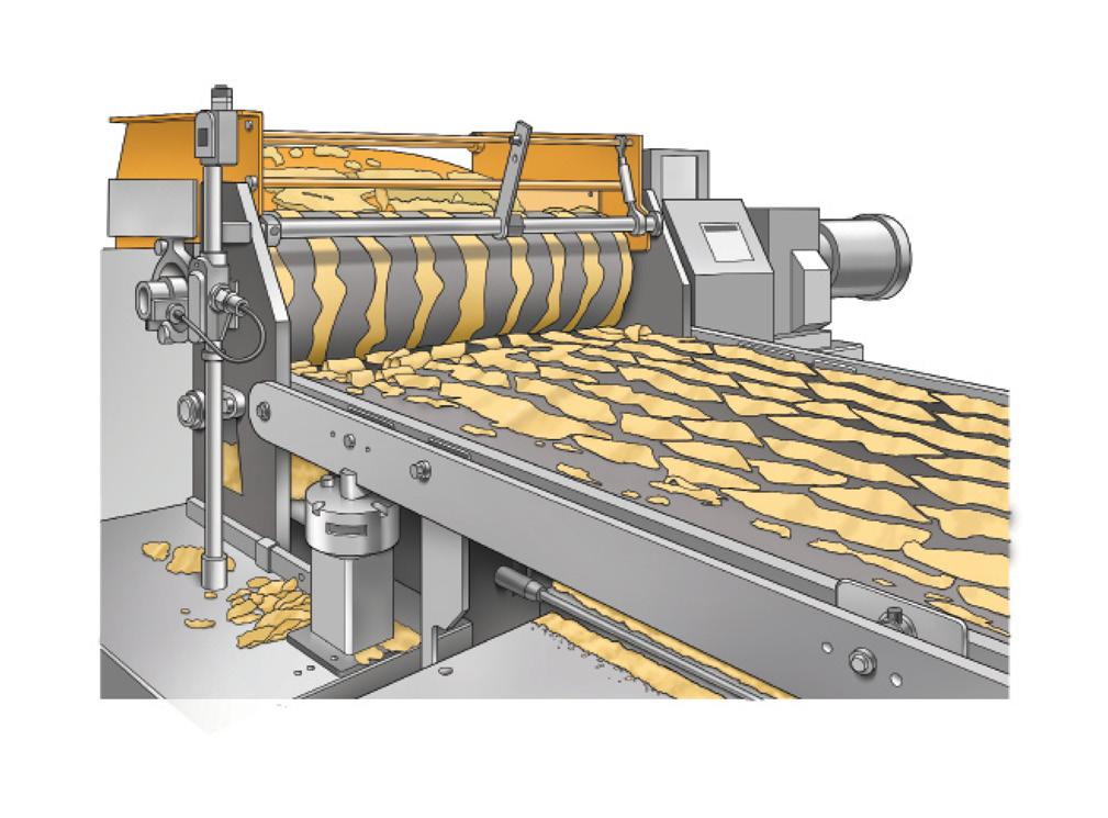
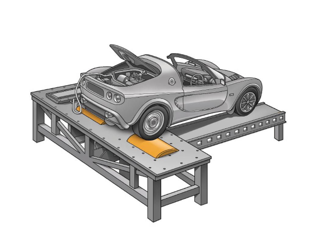
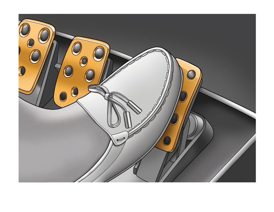
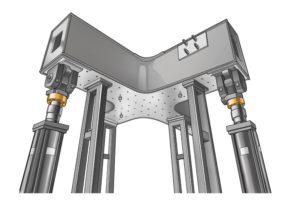
4 Application Examples Aircraft Jack Stand Environmental Test Load Stand Extrusion Control Dynamometer Structural Test Lab Pedal Force Measurements
5 Available Options Base plates Load receivers High Temperature Operation (to 400 F) In-Line Analog or Serial Transmitters Display/Control Instrumentation Junction/Summing Boxes Wireless Operation MS Connectors Shunt Calibration Use and Installation Guide Custom and OEM Solutions Application Recommendations / Suggestions The PA Series Compact Low Profile Load Cells are designed to be loaded in compression. The PA Series Load Cells are ideal for single or multiple load cell measurements typical of test and measurement, weighing, dynamic measurements, load testing systems and similar applications. When used in multiples, it is recommended that matched outputs be specified for optimum performance. Multiple load cell systems should include a Sentran summing/ junction box to correctly multiplex the load cell excitation and measurement signals. The most common loading method is to apply a force axially via the integral load button. Load introduction is best accomplished using devices such as a flat plate, a loading cup or similar interface providing a hardened mating surface to point load on the load button radius. The mating surface should be a slightly softer material than the load cell to prevent brinelling of the load button surface. Off-axis loads and shock loading should be avoided as degraded performance and/or damage to the load cell could occur. The support for the Load Cell must be rigid with the following characteristics: At least two or three times more rigid than the load cell. Possess a clean, flat and parallel surface to within 0.001in. TIR. A recommended surface finish of 63 micro-in. A minimum hardness of Rockwell B-100. The mounting side of the Load Cell must mate to the support surface. Mounting bolt torque values indicated on the data sheet should be used. In multiple load cell applications involving four or more supports, use care to ensure that the load on each load cell support varies by no more than 20% over the complete loading range. Balancing of the load can be accomplished by using shims, or similar mechanical components to achieve satisfactory load distribution. PA Series Compact Low Profile Load Cells are available in many capacity ranges. These load cells are designed to be used over the complete range of no load (0) up to the rated capacity. For example, 1,000 lbs. rated capacity PA Series are designed to be used for measurements within the range of 0 to 1,000 lbs. These load cells can be safely loaded to 150% of rated capacity without affecting the load cell performance within the capacity range. The reason for the variety of capacities is to allow the user to select the most ideal capacity for a given application. The most ideal capacity is one in which at least 80% of the capacity range is utilized at some point in the measurement process, without exceeding the rated capacity. This allows the load cell to deliver the highest signal to load ratio, and therefore the highest resolution and most stable measurement. There are other factors to consider, such as excitation voltage, but correct sizing of the load cell is the first step. Both the dead load and the live load need to be considered in determining the gross load and the load cell capacity. Contact Sentran s expert Applications Specialists for additional professional guidance


6 Commercial Information & Precautions WARNING! Do not exceed specified Maximum Load Limits. The Safe Load Limit is the point to which normal loading will not cause the load cell to experience an excessive zero shift or a degradation in performance. Use reasonable care when applying load to any load cell. Load limits can be exceeded due to shock loading (i.e. dropping a load onto a load cell), off axis loading, side loading and similar loading conditions that are beyond design capabilities. The structural integrity of all load bearing components in any load cell system should be designed with safety redundant load paths. (Overload stops, overhead load arrestors, etc.) The surfaces to which the load cell(s) is attached and/or is reacting against must be of sufficient structural integrity to carry loads up to and exceeding the ultimate ratings of the load cell(s) being used, while also taking into account any companion hardware being used in conjunction with the load cell. To ensure optimum performance, all measuring system cabling should be run through dedicated conduit when available. Avoid proximity to electrical noise sources and use of dirty power sources. The load cell cable shield should be connected to a dedicated instrument ground point only. Force measurement and weighing applications have numerous application-specific considerations to be addressed both mechanically and electrically. Therefore, installation of all system components are the responsibility of the user and should always be approved by a qualified, professional engineer. Any information provided by Sentran, LLC is intended only as informational and does not constitute a formal recommendation for the use of any product for any application. Sentran offers application/installation/use guides on request for most standard products. Please contact your Sentran representative for assistance, or visit our technical library resource at. PERSONAL INJURY! DO NOT USE these products as safety or emergency stop devices or in any other application where failure of the product could result in personal injury. MISUSE OF DOCUMENTATION The information presented in this datasheet is for reference only. DO NOT USE this document as product installation information. Complete installation, operation and maintenance information is provided in the instructions supplied with each product. Failure to comply with these instructions could result in death or serious injury. Legal Disclaimer ALL PRODUCTS, PRODUCT SPECIFICATIONS AND DATA ARE SUBJECT TO CHANGE WITHOUT NOTICE. Sentran, LLC, Incorporated, its affiliates, agents, and employees, and all persons acting on its or their behalf (collectively, Sentran, LLC ), disclaim any and all liability for any errors, inaccuracies or incompleteness contained herein or in any other disclosure relating to any product. The product specifications do not expand or otherwise modify Sentran, LLC s terms and conditions of purchase, including but not limited to, the warranty expressed therein. Sentran, LLC makes no warranty, representation or guarantee other than as set forth in the terms and conditions of purchase. To the maximum extent permitted by applicable law, Sentran, LLC, disclaims (i) any and all liability arising out of the application or use of any product, (ii) any and all liability, including without limitation special, consequential or incidental damages, and (iii) any and all implied warranties, including warranties of fitness for particular purpose, non-infringement and merchantability. Information provided in datasheets and/or specifications may vary from actual results in different applications and performance may vary over time. Statements regarding the suitability of products for certain types of applications are based on Sentran, LLC s knowledge of typical requirements that are often placed on Sentran, LLC products. lt is the customer s responsibility to validate that a particular product with the properties described in the product specification is suitable for use in a particular application. No license, express, implied, or otherwise, to any intellectual property rights is granted by this document, or by any conduct of Sentran, LLC. The products shown herein are not designed for use in life-saving or life-sustaining applications unless otherwise expressly indicated. Customers using or selling Sentran, LLC products not expressly indicated for use in such applications do so entirely at their own risk and agree to fully indemnify Sentran, LLC for any damages arising or resulting from such use or sale. Please contact authorized Sentran, LLC personnel to obtain written terms and conditions regarding products designed for such applications. Product names and markings noted herein may be trademarks of their respective owners. SENTRAN, LLC 4355 LOWELL STREET ONTARIO, CA , U.S.A. T: F: Sentran, LLC All Rights Reserved.