United Kingdom of Great Britain and Northern Ireland
|
|
|
- Octavia Richardson
- 5 years ago
- Views:
Transcription
 Regulations 2006 (SI 2006/1257) and")
1 (UK/0126/0016) MI-006 United Kingdom of Great Britain and Northern Ireland Certificate of EC type-examination of a measuring instrument Number: UK/0126/0016 revision 4 issued by the Secretary of State for Innovation, Universities & Skills Notified Body Number 0126 In accordance with the requirements of the Measuring Instruments (Automatic Catchweighers) Regulations 2006 (SI 2006/1257) and the Measuring Instruments (Non- Prescribed Instruments) Regulations 2006 (SI 2006/1270) which implement, in the United Kingdom, Council Directive 2004/22/EC, this certificate of EC type-examination has been issued to: AMCS Ltd. Fanningstown Crecora Co. Limerick Ireland in respect of a vehicle-mounted automatic catchweighing instrument designated the Single Unit Truck (SUT) and having the following characteristics: Maximum capacity Max 300 kg Minimum capacity Min 2.5 kg Scale interval e 0.5 kg Accuracy class Y(b) The necessary data (principal characteristics, alterations, securing, functioning etc) for identification purposes and conditions (when applicable) are set out in the descriptive annex to this certificate. This revision replaces previous versions of this certificate. Issue Date: 14 January 2009 Valid Until: 25 September 2017 Reference No: T1109/0024 Signatory: G. Glas for Chief Executive National Weights & Measures Laboratory Department for Innovation, Universities & Skills Stanton Avenue Teddington Middlesex TW11 0JZ United Kingdom
2 Descriptive Annex 1 INTRODUCTION This pattern of a battery-operated automatic catchweighing instrument, designated the Single Unit Truck (SUT), comprises a load cell, electronic equipment and position sensors mounted at the rear of a bin collection vehicle. This pattern automatically determines the weight of the loaded bin during the lifting process, then the weight of the empty bin on the way down to determine the net weight of refuse emptied. In addition, the bin is identified by an RFID tag reader system. The data is displayed on an indicator mounted near the operating console, and is sent to a host PC located in the cabin running the RouteMan software, before being sent to the central office via GSM network for storage and invoice purposes. This pattern is used to weigh individual bins, while two patterns connected in a master-slave arrangement are used to weigh large bins, both weights being added to obtain the total weight. 2 FUNCTIONAL DESCRIPTION 2.1 Mechanical Figure 1 shows a typical installation Load cell The pattern comprises one Vishay load cell type1320, maximum capacity 2000kg, mounted on the lifter at the rear of the vehicle (Figure 2). Its output is fed into an AD converter and it is calibrated through the Serial Test and Setup Programs Inclinometer The pattern comprises an inclinometer type ADXL311, mounted on the side of the lifter, to compensate for the pitch and roll of the vehicle. Its output is fed into an AD converter and it is calibrated through the Serial Test and Setup Programs Position sensor A position sensor type is connected to each SUT and is mounted on the lifter. Its output is fed into the AD converter and it is calibrated through the Serial Test and Setup Programs. The host PC software constantly monitors and reacts to its position. 2.2 Electrical The pattern operates from V DC, supplied from the 24 V DC vehicle battery. The indicator console is fitted with a non-volatile static RAM with integrated Lithium battery to maintain the basic functions such as clock, etc. A warning message is displayed when it needs replacing. Figure 3 shows the block diagram of a typical installation. 2/13
3 2.2.2 PCBs The system comprises two PCBs; the Control PCB and the I/O PCB, which are enclosed in an aluminium box mounted at the rear of the vehicle (Figure 4). The PCBs work on a 12V DC power, supplied from the cabin box through a converter, and is brought on the RS-485 line. A temperature sensor can be found on the Control PCB, which compensates the weighing at certain temperatures CPU The CPU, type 8051, is located on the Control board and holds the settings and calibrations for the SUT. It also contains the updated version of the weighing software. The Serial Test and Setup programs store setup and calibration settings onto the CPU Indicator The indicator is mounted at the rear of the vehicle near the operation console to be fully visible by the operator (Figure 5). It comprises an LCD screen (4 lines of 20 characters) and 8 LEDs. It indicates Weight in when a valid weight is received, as well as other weighing information such as date, time, RFID tag reference RFID tag reader Bins are equipped with RFID tags that are read via an antenna located at the rear of the vehicle (Figure 6) before and after every weighing operation in order to allocate the weight of refuse emptied to a particular customer and charge accordingly for it. The RFID reader is built on the Control board, and its status is constantly monitored; when a tag is in view it is immediately read. 2.3 Devices The instrument is not provided with any zero-setting or tare device due to its weighing principle. It is only used to calculate net weights by determining the difference between weights up and down, hence any error due to a drift of zero cannot affect the net result, provided the drift remains in an acceptable range. This is achieved by checking that the weight down measured on an empty bin is within Normal empty bin weight +/- 2% Max. If more than 5 consecutive weighings are found outside the range, an error message is displayed and weights can no longer be reported until the pattern is put into set-up mode for recalibration. Set-up mode is not available to the operator The SUT can be used to weigh in Static, Dynamic or StaticDynamic modes (see 3.3.2). Static mode can be used for individual bins up to 300 kg and large bins up to 600 kg. Dynamic and StaticDynamic modes can be used for individual bins up to 100 kg The SUT system is to be used to weigh individual bins. To weigh large bins, two SUTs must be installed in a master-slave type of connection. The user can then choose on the operating console the type of setting required. 3/13
4 3 TECHNICAL DATA 3.1 The system has the following technical characteristics: Individual bin Dynamic Individual bin Static Large bin Static Max (kg) Min (kg) e (kg) Load cell : Vishay type 1320 Load cell rated output signal : 2.0 mv/v Climatic environment : -10 C to +40 C Condensing, open Electromagnetic environment : E3 Mechanical environment : M3 Power supply : V DC Display location : Rear of the vehicle, near operating console Accuracy class : Y (b) 3.2 Documentation and drawings 3.3 Software Operation SUT_Manual_finaldraft3.1 SUT_RFID_Approvals SUT_Control_PCB_Layout SUT_IO_PCB_layout SUT_Display_PCB_layout SUT_Wiring_Schematic SUT_PCB_Schematics The following sequence of events applies: Bin is placed on lifting platform. Platform lifts bin to be dumped. RFID tag information is read. Lift position is monitored until optimum weighing position is reached. Lift is stopped and weighing starts. Weight is calculated and contents of bin dumped. Lift is stopped again during the down cycle and weight of empty bin measured. RFID tag is read again. Cycle complete Weighing algorithms and adjustments Weighing is usually set to start automatically based on the lifter position. There are three different weighing algorithms available; Static, Dynamic and DynamicStatic. The system operating temperature is taken into account as well. The weight is adjusted for high or low ambient temperature as measured by the onboard temperature sensor. The truck inclination is read and the final weight adjusted. 4/13
5 In Static mode a number of readings are taken while the lift is stopped. In Dynamic mode weights are taken continuously within a specified window of the lift position. DynamicStatic mode is a combination of both. In all cases different algorithms are used to determine the weight Start up Upon start up the system will initiate a full self-test to check the following components: EEP and Fram, Load cell, RFID antenna, LEDs. If any of them fails during the self-check, then a fail message will appear on the LEDs while the board is performing this check. Once the SUT Board has started up successfully it will display its SUT address number Version number It is possible to check the Software Version of the SUT Firmware using Serial Test: the version will be shown when Version is pressed. The version number includes a counter which increments each time the configuration is changed. There is no possibility for a user to reset or change this count. The version number is hard-coded into the binary file. The version number is of the following type: Savantech Ltd. SUTw Vx.y date z, where: Savantech Ltd. SUTw defines the type identification, with w a number greater than or equal to 1 x is a number greater than or equal to 2 that changes every time the legally relevant part of the software is modified or in case of a major modification of the software (any changes to the legally relevant software shall be notified to NWML) y a number greater than or equal to 0 that changes when minor modification are brought to the non-legally relevant part of the software date is the date of compilation, formatted as follow: yyyy_mm_dd z is a number greater than or equal to 1 that is incremented every time the setup is changed Example: Savantech Ltd. SUT1 V _09_ Security A checksum is included with the transmitted data as well as a known header and data structure information. Each measurement includes a time stamp, plus the unit s SUT number and check sum. Data is stored on the Alibi Checker software (Test Certificate GB-1225). It is not possible to read or change the code, and there is no provision for the end user to install new software or modify the weighing parameters. If too many transactions occur when the current transaction is meant to be stored, the buffer will become too full and an error message is sent. If there is no network service then no weights are displayed. 4 PERIPHERAL DEVICES AND INTERFACES 4.1 Interfaces The indicator may be fitted with the following interfaces: RS232 RS485 5/13
6 4.2 Peripheral devices The instrument may be connected to any peripheral device that has been issued with a test certificate by a Notified Body responsible for Annex B (MI-006) under Directive 2004/22/EC in any Member State and bears the CE marking of conformity to the relevant directives; or A peripheral device without a test certificate may be connected under the following conditions: it bears the CE marking for conformity to the EMC Directive 89/336/EEC; it is not capable of transmitting any data or instruction into the weighing instrument, other than to release a printout, checking for correct data transmission or validation; it prints weighing results and other data as received from the weighing instrument without any modification or further processing; and it complies with the applicable requirements of Directive 2004/22/EC Paragraph 8.1 of Annex I. 5 APPROVAL CONDITIONS The certificate is issued subject to the following conditions: 5.1 Legends and inscriptions The following legends are durably and legibly marked on a label (Figure 7) fixed on the control enclosure so that it is visible to the user (Figure 8): CE marking Supplementary metrology marking Notified Body verification mark Accuracy class Serial number Manufacturers mark or name Certificate number Max Min e= All components are identified by individual serial numbers. 6 LOCATION OF SEALS AND VERIFICATION MARKS 6.1 The CE mark shall be impossible to remove without damaging it. The labels shall be impossible to remove without them being destroyed. The markings and inscriptions shall fulfil the requirements of Paragraph 9 of Annex I of the Directive 2004/22/EC. 6.2 Any component that may not be dismantled or adjusted by the user must be secured by either a wire and seal or a tamper evident label and securing mark. The securing mark may be either: a mark of the manufacturer and/or manufacturer s representative, or an official mark of a verification officer 6/13
7 6.3 Every time the configuration or calibration is modified, the version number counter is incremented (see 3.3.4) and needs to be recorded on the instrument on a descriptive label near the rating plate. The label shall be impossible to remove without them being destroyed. 7 ALTERNATIVES 7.1 Having the SUT using any compatible load cell(s) providing the following conditions are met: There is a respective OIML Certificate of Conformity (R60) or a Test Certificate (EN45501) issued for the load cell by a Notified Body responsible for type examination under Directive 90/384/EEC. The certificate contains the load cell types and the necessary load cell data required for the manufacturer's declaration of compatibility of modules (WELMEC 2, Issue 2, 1996, section 11), and any particular installation requirements. A load cell marked NH is allowed only if humidity testing to EN45501 has been conducted on this load cell. The compatibility of load cells and indicator is established by the manufacturer by means of the compatibility of modules form, contained in the above WELMEC 2 document, at the time of verification or declaration of EC conformity of type. The load transmission conforms to one of the examples detailed in WELMEC 2.4 Guide for Load Cells. 7.2 Having RFID facilities removed from the system (RFID tag reader and antenna not installed), or not used (switched off by Host PC). The weighing process remains the same except that bins are not referenced, and therefore no RFID tag is stored as part of the measurement data. 7.3 Having the following software version number: The version number may be of the type: AMCS SUTw Vx.y date z, where: AMCS SUTw defines the type identification, with w a number greater than or equal to 1 x is a number greater than or equal to 2 that changes every time the legally relevant part of the software is modified or in case of a major modification of the software (any changes to the legally relevant software shall be notified to NWML) y a number greater than or equal to 0 that changes when minor modification are brought to the non-legally relevant part of the software date is the date of compilation, formatted as follow: yyyy_mm_dd z is a number greater than or equal to 1 that is incremented every time the setup is changed Example: AMCS SUT1 V _09_ /13
8 8 ILLUSTRATIONS Figure 1 Figure 2 Figure 3 Figure 4 Figure 5 Figure 6 Figure 7 Figure 8 Typical installation Loadcell mounted on lifter Block diagram Control and I/O boards in enclosure Indicator near operating console RFID antenna at rear of vehicle Rating plate Labelled control enclosure 9 CERTIFICATE HISTORY ISSUE NO. DATE DESCRIPTION UK/0126/ September 2007 Type examination certificate first issued. UK/0126/0016 rev 1 19 February 2008 Authorised alternatives 7.1 and 7.2 added. Application particularities removed (location of SUTs in master-slave mode, bin weights). Section 6.2 modified to include password protected access. Section modified to limit access to the configuration to installer only (not user). UK/0126/0016 rev 2 04 March 2008 Level of detail of the Certificate reduced (AD converters designations, weighing algorithms removed). UK/0126/0016 rev 3 28 March 2008 Sealing of the enclosure to protect the calibration and set-up button removed from Section 6.2. UK/0126/0016 rev 4 14 January 2009 Authorised alternative 7.3 added. 8/13


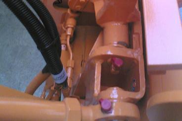
9 Figure 1 Typical installation Figure 2 Loadcell mounted on lifter 9/13
10 S.U.T. (Single Unit Truck) RFID Reader Load Cell AMP INA125 Ref R 619R 0.1% 10ppm ADC ADS bits RFID Reader RFID Antena IAref V Ref REF V µc RS V POT ADC AD7417AR 4 channels plus temperature 10 bits per channel Inclinometer X and Y Volt converter CAN BUS CAN BUS Control I2c and SPI i2c long distance Input / Output Control i/o Control Solid state relays Isolated inputs Digital OUT Lift Stop Lift Break LED / LCD Box LCD (20 x 4) LED s Ready Black ID Read ID Stop Figure 3 Block diagram 10/13


11 Figure 4 Control and I/O boards in enclosure Figure 5 Indicator near operating console 11/13

12 Figure 6 RFID antenna at rear of vehicle Figure 7 Rating plate 12/13


13 Figure 8 Labelled control enclosure Crown Copyright 2009 NATIONAL WEIGHTS AND MEASURES LABORATORY Department for Innovation, Universities & Skills 13/13